
Related Manuals for Servotronix CDHD Series


Summary of Contents for Servotronix CDHD Series
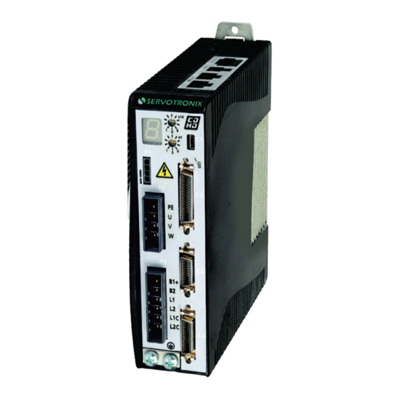
- Page 1 CDHD Servo Drive Pulse and Direction Using Single-Ended Signal Application Note Document Revision: 1.0 1.3.2 Firmware Version: 1.3.1.1 Software Version:...
- Page 3 Important Notice © 2013 Servotronix Motion Control Ltd. All rights reserved. No part of this work may be reproduced or transmitted in any form or by any means without prior written permission of Servotronix Motion Control Ltd. Disclaimer The information in this manual was accurate and reliable at the time of its release.
- Page 4 Pulse and Direction Using Single-Ended Signal Application Note...
-
Page 5: Table Of Contents
Pulse and Direction Using Single-Ended Signal Contents Overview ____________________________________________________ 7 Wiring ______________________________________________________ 9 Operation ___________________________________________________ 11 Operation Sequence Overview ..............11 Preliminary Procedures ................11 Step 1 – Select Pulse and Direction ............... 11 Step 2 – Confirm Digital Inputs 5 and 6 are Set to Pulse and Direction ....12 Step 3 –... - Page 6 Pulse and Direction Using Single-Ended Signal Application Note...
-
Page 7: Overview
Pulse and Direction Using Single-Ended Signal Overview Overview The CDHD’s Pulse and Direction Using Single-Ended Signal feature enables the connection of PLCs with a 24 VDC single-end signal to the CDHD. The following diagram shows how the feature is implemented. CDHD Pulse and Direction... - Page 8 Overview Pulse and Direction Using Single-Ended Signal Application Note...
-
Page 9: Wiring
Pulse and Direction Using Single-Ended Signal Wiring Wiring The Pulse signal is connected to CDHD fast digital input 5 – Controller I/F C2 pin 32. The Direction signal is connected to CDHD fast digital input 6 – Controller I/F C2 pin 15. - Page 10 Wiring Pulse and Direction Using Single-Ended Signal Application Note...
-
Page 11: Operation
Pulse and Direction Using Single-Ended Signal Operation Operation Note: The instructions in this document assume that you are familiar with ServoStudio software. Operation Sequence Overview The operation sequence is comprised of the following steps. Selecting Pulse and Direction motion. Confirming that digital inputs 5 and 6 are set, respectively, to Pulse and to Direction. -
Page 12: Step 2 - Confirm Digital Inputs 5 And 6 Are Set To Pulse And Direction
Operation Pulse and Direction Using Single-Ended Signal In the Gear Input pane, select the option Controller I/F Opto-Isolated and Pulse & Direction (P&D). Step 2 – Confirm Digital Inputs 5 and 6 are Set to Pulse and Direction Go to Drive Configuration > Digital IOs screen. Make sure digital input 5 is set to 17-Pulse signal. -
Page 13: Step 3 - Set Pulse And Direction Parameters
Pulse and Direction Using Single-Ended Signal Operation Step 3 – Set Pulse and Direction Parameters Return to the Motion screen. Select Multiplier. Note that the schematic diagram reflects the setting. It is strongly recommended that you enable Multiplier. This internal CDHD feature is functional in pulse and direction operation, and typically improves the Pulse and Direction reading. -
Page 14: Advance Settings
Operation Pulse and Direction Using Single-Ended Signal For example: A PLC controller is programmed to provide 1024 line pulses as an input command to a CDHD system in order to make the motor rotate two revolutions. The settings are therefore: External Encoder Resolution = 1024 Gear Ratio Multiplier = 2 Gear Ratio Divider = 1... -
Page 15: Summary Screen
Pulse and Direction Using Single-Ended Signal Operation Summary Screen When the CDHD is ready for Pulse and Direction Using Single-Ended Signal operation, the ServoStudio Motion screen settings will be as shown in the following figure. Actual values may differ. Application Note... - Page 17 Pulse and Direction Using Single-Ended Signal Application Note Revision 1.0 Servotronix - 21C Yagia Kapayim St. POB 3919 Petach Tikva 49130, Israel Tel: 972-3-927-3800 info@servotronix.com www.servotronix.com...
Need help?
Do you have a question about the CDHD Series and is the answer not in the manual?
Questions and answers