Table of Contents
Advertisement
Manual of Operation and Instruction
3
3
M
o
M
o
Before using the gauge, carefully read this manual. It
is especially important to understand the Safety
Warnings at the beginning of this manual. Keep this
manual in a safe place that is always easily accessible
during the use of the gauge.
Manual of Operation and Instruction3008 E. Cornwallis Road • P.O.
Research Triangle Park, NC 27709 U.S.A.
4
0
0
-
4
0
0
-
i
s
t
u
r
i
s
t
u
r
G
a
G
a
Troxler Electronic Laboratories, Inc.
Box 12057
Phone: 1.877.TROXLER
Outside the U.S.A.: +1.919.549.8661
Fax: +1.919.549.0761
www.troxlerlabs.com
B
S
e
B
S
e
e
-
D
e
e
-
D
e
u
g
e
u
g
e
NOTE
r
i
e
s
r
i
e
s
n
s
i
t
y
n
s
i
t
y
Advertisement
Table of Contents

Related Manuals for Troxler 3400-B Series


Summary of Contents for Troxler 3400-B Series
- Page 1 Warnings at the beginning of this manual. Keep this manual in a safe place that is always easily accessible during the use of the gauge. Troxler Electronic Laboratories, Inc. Manual of Operation and Instruction3008 E. Cornwallis Road • P.O. Box 12057 Research Triangle Park, NC 27709 U.S.A.
- Page 2 Troxler products are protected by U.S. and foreign patents. Copyright 1988 – 2011 Troxler Electronic Laboratories, Inc. All Rights Reserved No part of this manual may be reproduced or transmitted in any form or by any means, electronic or mechanical, including...
- Page 3 Model 3400-B Series...
- Page 4 Gilchinger Strasse 33 D.82239 1F, Bldg G, No. 1 Guotai North Road Alling nr. Munich, Germany ZJG, China, 215600 Phone: ++ 49.8141.71063 Phone: 0086.512.56793702 Fax: ++49.8141.80731 Fax: 0086.512.56793701 troxler@t-online.de kjin@troxlerlabs.cn To locate an independent, Troxler-authorized service partner near you, call 1.877.TROXLER (1.877.876.9537).
-
Page 5: Chapter 1: Introduction
ABOUT THIS MANUAL The 3400-B Series Manual of Operation and Instruction provides detailed instructions for the proper use and care of the 3401 and 3411 gauges as well as radiation safety information. Provides a brief overview of the gauges and their features... - Page 6 HOW TO USE THIS MANUAL The 3400-B Series Manual of Operation and Instruction contains information on safely using this unit. Also included in this manual are safety warnings, basic parameter setup, system troubleshooting, and general maintenance. Do not attempt to operate the gauges before reading this manual and the safety warnings posted on the units.
- Page 7 Indicates a procedure with multiple steps. Indicates a list of things needed (such as equipment) or important points to know. ♦ Indicates that more than one option is available. Carefully select the option that applies. Model 3400-B Series...
-
Page 8: Table Of Contents
TABLE OF CONTENTS CHAPTER 1: INTRODUCTION Introduction to the 3400 Series ..................1-2 Licensing and Regulations ....................1-4 CHAPTER 2: PARTS AND ACCESSORIES Unpacking and Inspection ....................2-2 CHAPTER 3: 3411 OPERATING PROCEDURES Taking Standard Counts ....................3-2 Taking Soil Measurements ....................3-4 Taking Asphalt Measurements .................. - Page 9 Working with Radiation Sources.................B-12 APPENDIX C : THEORY OF OPERATION Density............................C-2 Moisture........................... C-5 APPENDIX D : SPECIFICATIONS Measurement Specifications ...................D-2 Mechanical Specifications ....................D-4 Radiological Specifications ....................D-6 Electrical Specifications .....................D-7 APPENDIX E : STANDARD COUNT LOG WARRANTY Model 3400-B Series...
- Page 11 LIST OF FIGURES Figure 1. Gauge and Accessories ..............1-3 Figure 2. 3411-B Front Panel Controls ............2-4 Figure 3. 3401-B Front Panel Controls ............2-6 Figure 4. Roller Pattern ..................5-8 Figure 5. Thin Lift Overlay Nomograph (SI Units) ........ 5-10 Figure 6.
- Page 12 LIST OF TABLES Table 1. Sample Moisture Correction Chart ..........5-3 Table 2. Key Codes for Keyboard Test Routines ........6-10 Table 3. Radiation Profile................. B-9 Table 4. Neutron Thermalization and Absorption Data ...... C-6...
- Page 13 This chapter covers the following topics and tasks: An introduction to the 3401 and 3411 gauges Regulatory information Model 3400-B Series...
- Page 14 The 3400 series Surface Moisture-Density gauge is designed to measure the moisture content and density of soils, soil bases, aggregate, concrete, asphalt treated bases, and asphalt pavement. With a custom calibration or offset, the gauge can also be used on other materials. The 3400 series gauges allow you to quickly and precisely determine this moisture content and density without the use of core samples or other destructive methods.
-
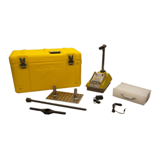
Page 15: Figure 1. Gauge And Accessories
Figure 1. Gauge and Accessories Model 3400-B Series... -
Page 16: Licensing And Regulations
If these sections are not completely understood, seek assistance from Troxler, an appointed Troxler representative, or others designated within the user organization. Additional nuclear safety information is available by completing our Nuclear Gauge Training course. - Page 17 This chapter covers the following topics and tasks: Performing an inventory and inspection Description of 3401-B and 3411-B controls Model 3400-B Series...
-
Page 18: Unpacking And Inspection
If the shipping case, any other part of the container, and/or the gauge appears to be damaged, notify the carrier and your Troxler representative immediately. For shipping to another location or back to the factory, save the box and any packing material. - Page 19 The second row of keys is used to determine which register will be displayed. The 〈MS〉 (Moisture Standard) and 〈DS〉 (Density Standard) keys are used to display the standard counts. The 〈MC〉 (Moisture Count) and 〈DC〉 (Density Count) keys are used to display the measure counts. Model 3400-B Series...
-
Page 20: Figure 2. 3411-B Front Panel Controls
Figure 2. 3411-B Front Panel Controls... - Page 21 6. Moisture correction switches are used to offset the gauges’ moisture readings. 7. The Depth switch is always set to the same value as the depth of the source rod when performing a measurements. Model 3400-B Series...
-
Page 22: Figure 3. 3401-B Front Panel Controls
The 3401 scaler is shown in Figure 3. The PWR/TIME switch is used to select SLOW, NORMAL, and FAST count times (4 minutes, 1 minute, and 15 seconds). The display switch chooses MOISTURE or DENSITY, and the 〈START〉 key begins count accumulation. Moving the MEAS/TST switch to TST toggles the test routine (see Chapter 6). - Page 23 Performing standard counts Instructions for taking measurements Setting target values NOTE For added safety, the source rods on the 3400 series gauges automatically retract to the SAFE position when picked up by the handle. Model 3400-B Series...
-
Page 24: Taking Standard Counts
1. Turn the gauge on. It will perform stabilization procedures. Please allow it to warm up for ten minutes. 2. Place the reference block on a solid surface with a density of 1600 kg/m (100 pcf) or greater, such as compacted soil, asphalt, or concrete. - Page 25 In the event that standard counts do not fall into the above percentages, an instability is suspected. Refer to page 6-3 for more information about stability (stat) tests. Model 3400-B Series...
-
Page 26: Taking Soil Measurements
1. If the surface is not relatively smooth, use the scraper plate provided with the gauge. Sand or native fines may used to fill voids. 2. Using the drill rod and drill rod guide, drive a hole at least 2 inches (50 mm) deeper than the desired test depth. - Page 27 2. Press 〈WD〉 and record the Wet Density (kg per cubic meter or PCF). 3. Press 〈M〉 and record the Moisture. 4. Press 〈DD〉 and record the Dry Density (WD-M). 5. Press 〈%M〉 and record percent moisture (M divided by DD) Model 3400-B Series...
-
Page 28: Taking Asphalt Measurements
1. Place the gauge on the surface of the asphalt, choosing a smooth surface for best results. Sand can be used to fill large voids. Care must be taken to ensure that the gauge is resting on the asphalt and not on the sand. This procedure is only helpful when the voids are large. - Page 29 If the value is too high, utilize the same procedure but with the switch on (-). 3. On soils and bases, press 〈SHIFT〉 and 〈%PRO〉 to read the percent Proctor. 4. On asphalt, press 〈SHIFT〉 and 〈%MAR〉 to read the percent Marshall. Model 3400-B Series...
- Page 30 NOTES...
- Page 31 This chapter covers the following topics and tasks: Performing standard counts Instructions for taking measurements NOTE For added safety, the source rods on the 3400 series gauges automatically retract to the SAFE position when picked up by the handle. Model 3400-B Series...
- Page 32 1. Turn the gauge on. It will perform stabilization procedures. Please allow it to warm up for ten minutes. 2. Place the reference block on a solid surface with a density of 1600 kg/m (100 pcf) or greater, such as compacted soil, asphalt, or concrete.
- Page 33 In the event that standard counts do not fall into the above percentages, an instability is suspected. Refer to page 6-3 for more information about stability (stat) tests. Model 3400-B Series...
-
Page 34: Taking Soil Measurements
1. If the surface is not relatively smooth, use the scraper plate provided with the gauge. Sand or native fines may used to fill voids. 2. Using the drill rod and drill rod guide, drive a hole at least 2 inches (50 mm) deeper than the desired test depth. - Page 35 If a correction factor is necessary, it can be determined by following the procedures starting on page 5-2. A correction factor for a given soil need only be determined once. The correction can then be reused in future testing with the same gauge. Model 3400-B Series...
-
Page 36: Taking Asphalt Measurements
1. Place the gauge on the surface of the asphalt, choosing a smooth surface for best results. Sand can be used to fill large voids. Care must be taken to ensure that the gauge is resting on the asphalt and not on the sand. This procedure is only helpful when the voids are large. -
Page 37: Trench Measurements
This section covers the following topics and tasks: Correction factors Trench measurements Thin lift overlays Roof moisture measurements Model 3400-B Series... - Page 38 For a general discussion of calibration, see page A-10. If working with coal, see page 5-14. For other applications, contact your Troxler representative. Moisture Correction The 3400 series measures moisture by determining the hydrogen (H) content of the soil and relating this to water (H content.
- Page 39 Dial this value into the moisture correction switches on the 100 + %M Gauge 3411-B scaler, paying attention to the algebraic sign. In the example above, the moisture correction is: -2.5 x 1000 = -23 100 + 8.0 Model 3400-B Series...
- Page 40 The correction is independent of dry density and wet density and adjusts the apparent moisture to true moisture regardless of dry density. This value can be used for all future tests on the same soil type. NOTE Occasionally, non-homogenous soils may be encountered in which differences between oven dry and gauge readings are not consistent.
- Page 41 3. Determine the moisture offset value by subtracting the moisture standard count from the second moisture count obtained in the trench. Record this number for future tests performed at this site and with this gauge at the same distance from the wall. Model 3400-B Series...
- Page 42 Subtract the offset value from the moisture measurement count ON THE 3401 before you divide by the moisture standard count. Set this value on the MOISTURE CORRECTION switches. Press ON THE 3411 and hold the 〈SHIFT〉 key while depressing 〈MC〉. The value set on the MOISTURE CORRECTION switches should now appear on the display.
- Page 43 Each test must be 95% or over and the average must be 98% or over. A new control section must be established when the material source has changed or after 10 test sections have been approved. Model 3400-B Series...
-
Page 44: Figure 4. Roller Pattern
Figure 4. Roller Pattern... -
Page 45: Thin Lift Overlays
NOTE These procedures and nomographs are applicable only to the 3401-B and 3411-B gauges. They are not valid for other Troxler gauges or gauges from other manufacturers. Following are examples with nomographs for SI and US Customary Units. -
Page 46: Figure 5. Thin Lift Overlay Nomograph (Si Units)
Overlay Example – SI Units In this example, the bottom layer density (left scale) is 2080 kg/m with a mat 30 mm thick overlaying it. A backscatter density test on the top of the mat (right scale) yielded a result of 2220 kg/m (right) and extended to the right. -
Page 47: Figure 6. Thin Lift Overlay Nomograph (Us Customary Units)
1.2 inches (bottom) and 138.5 pcf (right) and extended to the right. The correct density for the top layer is then read from the nomograph as 144.5 on the right scale. Figure 6. Thin Lift Overlay Nomograph (US Customary Units) Model 3400-B Series 5-11... -
Page 48: Roof Moisture Measurements
The 3400 can be used easily and effectively for determining the presence of elevated moisture levels in built-up roofing systems. Troxler also manufacturers the Model 3216, which is specifically designed for roof moisture measurement. To test roofs for moisture, a grid is first established on the roof to be surveyed. -
Page 49: Figure 8. Midpoint Of Interval
This area can then be “cut” into three or four levels for further interpretation. You may wish to consider taking core samples based on histogram analysis as a means of determining absolute moisture content. Model 3400-B Series 5-13... - Page 50 The wet density of coal often lies below the calibrated range of 1100-2700 kg/m (70-170 pcf) of the gauge. Many users adjust the calibration using samples prepared to simulate field conditions. A minimum of three to four “standards” should be constructed, each having dimensions of 50 cm x 50 cm (20 in.
- Page 51 This section covers the following topics and tasks: Electrical components Stat, drift, and other tests Model 3400-B Series...
-
Page 52: Electronic And Detector Service
The 3400-B series utilizes a high degree of integrated circuit technology. For this reason the reliability level is very high and repair is relatively simple because it consists of module or PC Board replacement. If the gauge will not perform the functions described in the operating procedures, refer to the Troubleshooting section (starting on page A-7) or contact a Troxler representative. -
Page 53: Stability And Drift Tests
2%. If the standard counts fail one or both of the above tests, return the gauge to the lab to perform statistical stability (stat) and drift tests. Model 3400-B Series... - Page 54 If the gauge is unstable after replacing the moisture module, high voltage module, He tube, contact your Troxler service department. 6. Divide the standard deviation of the density readings by the average density reading. If this ratio is not within the range of 0.17 to 0.33, check or replace the density module and/or...
- Page 55 5. If the difference between this average and the average taken in the stat test is greater than 0.5% for density, check and replace the density module. If the gauge is still drifting, check and replace the G-M tubes. Model 3400-B Series...
-
Page 56: Figure 9. Statistical Stability Test
The following is an example of the stat test and drift test. Figure 9. Statistical Stability Test... -
Page 57: Gauge Base Electronics
±0.1 volts. Another voltage sensing circuit detects when the battery voltage drops below 8.4 ±0.1 volts and cuts off the gauge electronics. NOTE Either the 3401-B or 3411-B may be operated with a “non-B” base by use of an adapter cable (part number 102855). Model 3400-B Series... -
Page 58: Figure 10. 3411-B Display Test Sequence
3411-B Scaler Module Test Functions The 3411-B microprocessor controls the majority of the instrument’s functions. If the display indicates four zeros (0000) when the instrument is turned on, the microprocessor is probably working normally. If the microprocessor is working, there are three self-test routines that can be used to verify proper operation. -
Page 59: Figure 11. 3411-B Rotary Switch Test Format
If other codes are produced or if only one code is shown and does not change, then the keyboard or associated circuits are defective. NOTE The depth switch must be in backscatter position for this test. Model 3400-B Series... - Page 60 Table 2. Key Codes for Keyboard Test Routines 3411-B Oscillator and Prescalers Test To check the oscillator and the moisture and density prescalers: 1. Unscrew the front panel. 2. Slide the MEAS/TST switch to the TST position and replace the module. 3.
- Page 61 & & This section covers the following topics and tasks: Maintenance tasks Troubleshooting Returning the gauge for service Model 3400-B Series Appendix A-1...
-
Page 62: Charging Batteries
A fully charged battery will last for eight weeks under normal working conditions before needing to be recharged. When the gauge displays BAT on the display, the gauge has only a few hours left before automatically turning off. The batteries can then be fully recharged with the AC charger. Give the batteries a full charge when recharging;... -
Page 63: Mechanical Maintenance
To ensure the integrity of the source rod, Troxler recommends that a qualified service person inspect the gauge and the source rod periodically. When the source rod is pulled out of the ground and into the safe position, the scraper ring should clean the source rod. This ring is located on the bottom plate at the base of the gauge. - Page 64 If dirt is present, replace the scraper ring (Troxler part number 012752). b. For reinstalling, note how the retaining ring and scraper ring are installed. c. Remove the retaining ring from the back of the bottom plate with a screwdriver.
- Page 65 If the source rod will not come down easily or not at all, the bearings will need to be changed. Send the gauge to a Troxler service center if the bearings need to be replaced. Trigger Mechanism Assembly This procedure is for replacing the trigger mechanism assembly on serial numbers 10245 and 10256 and above.
- Page 66 Gaskets The gauge has three gaskets that will need to be checked at least once or twice a year. These gaskets will seal the gauge from the environment, and, if not inspected, moisture or water can get inside the gauge and cause damage. ♦...
-
Page 67: Troubleshooting
Replace Front Panel Module Before replacing the Front Panel Module, set the MEAS/TST switch on TST and attempt to accumulate a set of counts. If the TST count is correct, the front panel module is probably functioning correctly. Model 3400-B Series Appendix A-7... - Page 68 Replace Density Module. Instrument counts moisture but not density. Replace Front Panel Module Replace G-M tubes. Replace the Moisture Module. Instrument counts density but not moisture. Replace the Front Panel Module Replace the He tube.
- Page 69 Same as above. Positive overflow in division. Invalid input from Switch failure, I/O board MOISTURE failure, or operator induced CORRECTION switches. error during chain calculations. Same as above. Invalid input from DEPTH switch. Model 3400-B Series Appendix A-9...
-
Page 70: Calibration
The 3400 Series gauges are calibrated at the factory to relate count ratios to standards of known density and moisture. For density, materials that have proven to be dependable standards are: aluminum, magnesium, granite, limestone, and layered magnesium/polyethylene. These standards cover the range of densities and moistures for which the gauges are used. - Page 71 Moisture calibration need not be checked as the detectors are very stable. Small changes can be corrected in the field when field samples are taken to develop a moisture correction factor. If recalibration is necessary and Troxler standards are not available, contract your Troxler service center with calibration capability.
-
Page 72: Returning The Gauge For Service
Troxler personnel to expedite the repair work. To obtain an RGA number, please complete the electronic form (available on the Troxler website) and fax it to the factory or branch office. If you do not use the form, please have the following... -
Page 73: Replacement Parts
Replacement parts and accessories can be order through your Troxler representative or by calling 1-877-TROXLER. Part Number Description 110247 Advanced Control Unit (ACU) 103280 Battery Monitor Module (Rev) 102057 Battery Pack Assembly 3400 (2 required before SN 10278) 103681 Battery Pack Assembly 3400 (2 required... - Page 74 10245 and 10256 and after) 103276 HV Power Supply Assembly (1000 V) 102116 Indexer Assembly 3400 (before SN 10256 except 10245) 103021 012185 Lock with 2 Keys (H-1209) 012176 Lock with two keys (SN before 14410) 103397 Moisture PreAmp 6.5V Module 103787 Plunger 3400 (Indexer for SN 10245-14409) 104553...
- Page 75 Radiation Sign Kit 103484 Reference Standard, 3400 102111 Scraper Plate 109661 Survey Meter Maintenance Supplies Part Number Description 012784 Magnalube, 1.5 oz tube 012786 Magnalube, 1 lb can 012789 Magnalube, 14.5 oz 100761 Source Rod Pig Model 3400-B Series Appendix A-15...
- Page 76 NOTES Appendix A-16...
-
Page 77: Radiation Theory And Safety
& & This section covers the following topics and tasks: Radiation theory and safety Working with radiation sources 3400-B radiation profile Model 3400-B Series Appendix B-1... - Page 78 For a more detailed discussion of radiological theory, please reference the Troxler Nuclear Gauge Safety Training Program manual, provided during the Troxler safety class or is available for purchase at our website (http://www.troxlerlabs.com). Atomic Structure All materials consist of chemical elements that cannot decompose by ordinary chemical methods.
- Page 79 "half-life." The half-life of cesium-137 is 30 years, while that of americium 241:beryllim is 432 years. Model 3400-B Series Appendix B-3...
- Page 80 Radiation Terminology Various standards for the measurement of radiation exist, but only two concerns the Troxler 3400-B Series gauge user. These units are the curie, which expresses activity of the source, and the rem (roentgen equivalent man). The curie, defined as the quantity of radioactive material giving 3.7 x 10...
- Page 81 1 standard deviation of the mean. Figure 14 shows the probabilities for three different standard deviations. A statistical stability test may be performed to compare the experimental standard deviation to the theoretical standard deviation. Model 3400-B Series Appendix B-5...
- Page 82 Radiation Safety This section provides a brief discussion of general radiation safety. The exposure profile for a 3400 series gauge is also included, along with a discussion of the source encapsulation. The radioactive sources in a 3400 series gauge produce three TYPES OF RADIATION types of radiation: Alpha Particles...
- Page 83 (Figure 15). Doubling the distance from a radiation source reduces the exposure to one-fourth its original value. If the distance is tripled, the exposure is reduced by a factor of nine, etc. Model 3400-B Series Appendix B-7...
- Page 84 Figure 14. Effects of Distance on Exposure Shielding is any material used to reduce the radiation reaching SHIELDING the user from a radioactive source. While some types of radiation such as alpha particles may be stopped by a single sheet of paper, other particles such as neutrons and photons require much more shielding.
- Page 85 Model NP-2 survey meter, calibrated Feb. 28, 1982. 3. Dose Rates are for 8 mCi Cs-137gamma source and 40 mCi am-241:besource 4. * indicates a reading less than 9.1 mrem/hr. 5. All units are in mrem/hr. Model 3400-B Series Appendix B-9...
- Page 86 Left Side Back Right Side Front Bottom SURFACE 30 cm 1 meter 3401 IN CASE GAMMA NEUTRON TOTAL GAMMA NEUTRON TOTAL GAMMA NEUTRON TOTAL RIGHT LEFT BOTTOM BACK FRONT 3411 IN CASE GAMMA NEUTRON TOTAL GAMMA NEUTRON TOTAL GAMMA NEUTRON TOTAL RIGHT LEFT...
- Page 87 The photon source (cesium-137) is sealed in a welded capsule. The only radiological health concerns to Troxler 3400-B Series gauge users are the photon and neutron emissions for moisture and density measurement. Proper use of this instrument...
- Page 88 The 3400-B series contains two radioactive sources. The Am- 241:Be source is located in the center of the gauge base. Never The Cs-137source is welded inside the tip of the source rod. attempt to remove this source! When located in the SAFE (shielded) position, the source is surrounded on all sides by tungsten and radiation is reduced to safe levels.
- Page 89 This section covers the following topics and tasks: How the gauge detects moisture and density Model 3400-B Series Appendix C-1...
-
Page 90: Density
Figure 16 represents the geometry for the direct transmission and backscatter modes of the 3400 series. An 8 mCi (0.3 GBq) Cs-137source is located in the tip of the rod. Gamma photons emitted by the source radiate to the detectors. Some of the photons emitted by the source collide with electrons in the soil, reducing the amount of gamma photons reaching the detectors. - Page 91 Figure 15. Direct Transmission and Backscatter Geometries Model 3400-B Series Appendix C-3...
- Page 92 Figure 16. Backscatter Surface Density Effects Appendix C-4...
-
Page 93: Moisture
The tube is insensitive to fast neutrons, so no shielding is required between the source and the detector. Generally, the counts obtained from a He tube are directly proportional to hydrogen, or moisture, content. Model 3400-B Series Appendix C-5... - Page 94 Neutron Thermalization and Absorption Data Element Collisions to Absorption Cross Thermalization Section Hydrogen 19.0 0.33 Boron 109.2 750.00 Carbon 120.6 0.0034 Nitrogen 139.5 1.90 Oxygen 158.5 0.0002 Sodium 224.9 0.53 Magnesium 237.4 0.063 Aluminum 262.8 0.23 Silicon 273.3 0.16 Phosphorous 300.8 0.19 Sulfur...
- Page 95 Depth (in) = 11 - 0.17 M (pcf) Depth (mm) = 280 - 0.27 M (kg/m This equation covers 98% of the measured volume and is valid over the moisture content range of 0-640 kg/m (0-40 pcf). Model 3400-B Series Appendix C-7...
- Page 96 DepthE "' 11 - (0.17 X M) 32.3 pcf :::, "6 20.8 pcf "'O :::, 5.95 pcf Depth (in) Depths "' 280 - (0.27 X M) kg/m3 :::, kg/m3 "6 "'O :::, kg/m3 Depth (mm) Figure 17. Effect of Moisture on Depth Appendix C-8...
-
Page 97: Measurement Specifications
This section covers the following topics and tasks: Measurement specifications Mechanical specifications Calibration specifications Radiological specifications Electrical specifications Model 3400-B Series Appendix D-1... - Page 98 Backscatter Density Fast Normal Slow Precision at 2000 kg/m 16.6 8.30 4.15 ±kg/m (125 pcf) 1.04 0.52 0.26 ±pcf Depth of Measurement (98%) 100 mm (4 inches) Direct Trans. Density Fast Normal Slow Precision at 2000 kg/m 9.38 4.69 2.35 ±kg/m (125 pcf) 0.59...
- Page 99 For direct transmission density, a 100% void of 1.25 mm (0.05 inches) will cause a negative bias of 14.4 kg/m (0.90 pcf). For moisture, a 100% void of 1.25 mm (0.05 inches) will cause a negative bias of 17.6 kg/m (1.10 pcf). Model 3400-B Series Appendix D-3...
- Page 100 Gauge base and Aluminum casting topshell Vibration test 2.5 mm (0.1 inches) at 12.5 Hz Drop test 300 mm on 25 mm diameter steel ball Operating Ambient: -10 t0 70°C (14 to 158°F) temperature Surface: 170°C (350°F) Storage temperature -55 to 85°C (-70 to 185°F) Gauge size 368 x 229 x 183 mm (excluding handles)
- Page 101 If the optimum density has been preset by the operator, the microprocessor can compute % of Marshall or % of Proctor. A method has also been provided to allow operators to negate the effects of sidewall moisture, if necessary. Model 3400-B Series Appendix D-5...
- Page 102 Gamma source 0.40 GBq (8 mCi) ±10% cesium-137, TEL A-10112 Neutron source 1.48 GBq (40 mCi) ±10% Americium- 241:Beryllium with 70,000 N/sec yield, TEL A-102451 Source form Stainless steel, double encapsulated Shielding Tungsten and lead Surface dose rates 15 mrem/hour max, neutron and gamma Source rod Stainless steel, 55 C Rockwell hardness...
- Page 103 0.09 0.15 Power consumption after automatic 0.001 0.001 battery cutoff (watts) Battery packs are protected against overcharge and over discharge. A low battery alarm is indicated by the display several hours prior to automatic shutoff. Model 3400-B Series Appendix D-7...
- Page 105 Model 3400-B Series Appendix E-1...
-
Page 106: Appendix E : Standard Count Log
STANDARD COUNT LOG Serial Number Date Moisture - MS Density - DS Date Moisture - MS Density - DS Appendix E-2... - Page 107 STANDARD COUNT LOG Serial Number Date Moisture - MS Density - DS Date Moisture - MS Density - DS Model 3400-B Series Appendix E-3...
- Page 108 NOTES Appendix E-4...
- Page 109 TROXLER’s obligation under this warranty shall be limited exclusively to the repair at a TROXLER facility at no charge, except for shipping to and from TROXLER’S plant, of any instrument which may prove defective under normal use and which TROXLER’s examination shall disclose to its satisfaction to be thus defective.
Need help?
Do you have a question about the 3400-B Series and is the answer not in the manual?
Questions and answers