Table of Contents
Advertisement
Quick Links
Manual of Operation and Instruction
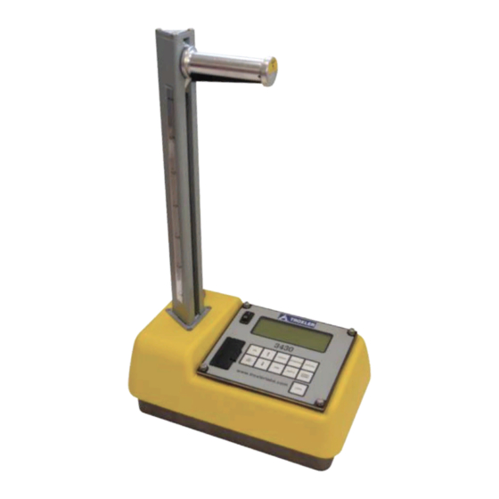
Model 3430 Plus & 3440 Plus
Surface Moisture-Density Gauge
The Model 3440 Plus Surface Moisture Density Gauge can
be equipped with an optional global positioning system (GPS)
receiver. If such a gauge is moved a long distance between uses,
the GPS system must be allowed to initialize. In some instances,
initialization may take as long as 30 to 45 minutes from the time
the gauge is powered on with the GPS enabled. Note also that
the gauge must be positioned such that the GPS receiver can
receive signals from the GPS satellites (see Appendix I for more
information). If the GPS does not initialize within 45 minutes,
contact your Troxler representative.
Troxler Electronic Laboratories, Inc.
3008 Cornwallis Rd. • P.O. Box 12057
Research Triangle Park, NC 27709
Phone: 1.877.TROXLER
Outside the USA: +1.919.549.8661
Fax: +1.919.549.0761
www.troxlerlabs.com
NOTE
Advertisement
Chapters
Table of Contents

Related Manuals for Troxler 3430 Plus


Summary of Contents for Troxler 3430 Plus
- Page 1 Manual of Operation and Instruction Model 3430 Plus & 3440 Plus Surface Moisture-Density Gauge NOTE The Model 3440 Plus Surface Moisture Density Gauge can be equipped with an optional global positioning system (GPS) receiver. If such a gauge is moved a long distance between uses, the GPS system must be allowed to initialize.
- Page 2 Troxler gauges are protected by U.S. and foreign patents. Copyright 2007 – 2009 Troxler Electronic Laboratories, Inc. All Rights Reserved No part of this manual may be reproduced or transmitted in any form or by any means, electronic or mechanical, including...
- Page 3 Model 3430 Plus & 3440 Plus...
- Page 4 11300 Sanders Drive, Suite 7 Rancho Cordova, CA 95742 Fax: 916.631.0541 Troxler European Subsidiary Troxler Electronics GmbH Gilchinger Strasse 33 D.82239 Alling nr. Munich, Germany Phone: ++49.8141.71063 Fax: ++49.8141.80731 E-mail: troxler@t-online.de NOTE To locate an independent, Troxler-authorized service partner near you, call 1.877.TROXLER (1.877.876.9537).
- Page 5 HOW TO USE THIS MANUAL Congratulations on the purchase of a Troxler Model 3430 Plus or 3440 Plus Surface Moisture-Density Gauge. Troxler continues the proven technology of its 3400 Series surface moisture-density gauges with the Troxler Model 3430 Plus and 3440 Plus.
- Page 6 CONVENTIONS USED IN THIS MANUAL Throughout this manual, symbols and special formatting are used to reveal the purpose of the text as follows: WARNING Indicates conditions or procedures that, if not followed correctly, may cause personal injury. CAUTION Indicates conditions or procedures that, if not followed correctly, may cause equipment damage.
- Page 7 NOTES Model 3430 Plus & 3440 Plus...
-
Page 8: Table Of Contents
TABLE OF CONTENTS CHAPTER 1. INTRODUCTION Introduction ................... 1–2 Gauge Parts and Accessories ............1–5 Unpacking and Inspection ............1–7 CHAPTER 2. THEORY OF OPERATION Density ..................2–2 Moisture ..................2–3 Calibration ..................2–5 CHAPTER 3. GETTING STARTED Gauge Illustration ................. 3–2 Control Panel ................ - Page 9 Software Reset ................9–8 Test Menu ..................9–9 APPENDIX A. RADIATION THEORY AND SAFETY Radiation Theory ................A–2 Radiation Safety ................A–5 Regulatory Requirements ............A–14 Gauge Use Precautions ............... A–17 Radiation Profile................. A–18 Model 3430 Plus & 3440 Plus...
- Page 11 TABLE OF CONTENTS (Continued) APPENDIX B. TRANSPORTATION AND SHIPPING U.S. Shipping Requirements ............B–2 Canadian Shipping Requirements ..........B–4 APPENDIX C. TROUBLESHOOTING AND SERVICE Troubleshooting ................C–2 Display Contrast ................C–9 Batteries ..................C–10 Mechanical Maintenance ............C–15 Replacement Parts............... C–18 Returning the Gauge for Service ..........
- Page 12 Adjusting the Display Contrast ......... C–9 C–2 NiMH Battery Pack and AA Batteries ....C–11 C–3 Final Assembly, Part Numbers 110795_XXXX (3430 Plus) and 110800_XXXX (3440 Plus) ..C–19 C–4 Base Assembly, Part Number 110015_XXXX ..C–21 C–5 Scaler Assembly, Part Numbers 110791 (3430 Plus) and 110876 (3440 Plus) .......
- Page 13 LIST OF TABLES Table Title Page 3–1 Key pad Functions ............3–4 A–1 Radiation Profile for Gauge ........A–19 C–1 Error Messages ............C–6 C–2 Typical Battery Operating Life .......C–11 I–1 GPS Position Accuracy ..........4...
- Page 14 NOTES Model 3430 Plus & 3440 Plus...
- Page 15 ATTENTION MODEL 3430 PLUS OR 3440 PLUS GAUGE OWNER This unit contains functions that require an ACCESS CODE. This code must be entered before these functions may be used. For more information on using the access code, refer to Chapter 9.
- Page 16 NOTES...
- Page 17 CHAPTER 1 INTRODUCTION This chapter provides a brief overview of the Troxler Model 3430 Plus and 3440 Plus Surface Moisture-Density Gauges, and includes a list of the gauge parts and accessories, as well as instructions for unpacking and inspecting the gauge.
- Page 18 Using the Model 3430 Plus and 3440 Plus gauges, the operator can quickly and precisely measure the moisture content and density of construction materials. Both gauges feature: ♦...
- Page 19 For more information on the GPS option, refer to Appendix I. The Model 3430 Plus and 3440 Plus gauges meet or exceed all applicable American Society of Testing and Materials (ASTM) standards (or corresponding equivalent), including: ♦...
- Page 20 Any licensing issues discussed in this manual are for the United States. To purchase a Model 3430 Plus or 3440 Plus in Canada, owners must obtain a radioisotope license from the Canadian Nuclear Safety Commission (CNSC). The owner should obtain copies of the CNSC Regulations and the Transportation of Dangerous Goods Act and Regulations (TDG).
-
Page 21: Gauge Parts And Accessories
GAUGE PARTS AND ACCESSORIES Figure 1–1. Gauge Parts and Accessories Model 3430 Plus & 3440 Plus 1–5... - Page 22 1. The Gauge is the portable instrument containing all electronic modules, the rechargeable battery pack, detectors, and the radioactive sources. 2. The Reference Standard Block provides a measurement standard for standard counts. It is also used during stability and drift tests. 3.
-
Page 23: Unpacking And Inspection
UNPACKING AND INSPECTION Troxler recommends that the operator wear a dosimeter while working with the gauge. Upon receipt of the gauge from the factory, perform a complete inspection and inventory. If the shipping case and/or any other part or accessory appears damaged, notify the carrier and your Troxler Representative immediately. - Page 24 Lift the gauge from the transport case and inspect the outside surface for damage. Check the lock on the source rod handle and make sure the keys fit. Remove the lock, release the trigger, and check the source rod operation. It should move up and down with little effort.
- Page 25 THEORY OF OPERATION This chapter provides a brief description of the theory of operation of the Troxler Model 3430 Plus and 3440 Plus Surface Moisture- Density Gauges. The direct transmission and backscatter modes of operation are illustrated, along with an explanation of the cesium-137 source, americium-241:beryllium source, and detector geometry.
-
Page 26: Density
DENSITY The Troxler Model 3430 Plus and 3440 Plus Surface Moisture- Density Gauges use two modes of operation: direct transmission mode (with the source rod extended into the material to be measured) and backscatter mode (with the source rod in the backscatter position, just above the surface of the material). -
Page 27: Moisture
× Depth (mm) = 280 – (0.27 M), where: M = moisture in kg/m The normalized curve set shown in Figure 2–1 illustrates the effects of moisture content on the depth of measurement. Model 3430 Plus & 3440 Plus 2–3... - Page 28 Depth = 11 - (0.17 X M) 32.3 pcf 20.8 pcf 5.95 pcf Depth (in) Depth = 280 - (0.27 X M) 521 kg/m 336 kg/m 96 kg/m Depth (mm) The dotted lines indicate the maximum depth of gauge measurement at a given soil moisture content. Figure 2–1.
-
Page 29: Calibration
CALIBRATION Troxler calibrates the gauge at the factory and recommends that it always be calibrated by an authorized Troxler service center. For a list of Troxler and authorized Troxler service centers, refer to page iii of this manual or visit the Troxler website at www.troxlerlabs.com/SERVICES/services.shtml. - Page 30 NOTES 2–6...
- Page 31 Daily Inspection ................3–6 Turning the Gauge On ..............3–7 Setup ..................... 3–9 Setup Menu ................3–9 Extended Menu ..............3–11 Measurement Mode .............. 3–15 Project Function ..............3–16 Display Backlight ..............3–16 Model 3430 Plus & 3440 Plus 3–1...
-
Page 32: Gauge Illustration
GAUGE ILLUSTRATION Figure 3–1 illustrates various components of the gauge referred to throughout this chapter and the remainder of the manual. Figure 3–1. Gauge Illustration 3–2... -
Page 33: Control Panel
RS-232 port, and keypad. The keypad allows the operator to access the gauge software. Troxler designed the keypad for ease of use, with large keys and an anti-glare coating. Pressing a function key activates the function only when the Ready screen is displayed. Table 3–1 describes the function of each key. - Page 34 Table 3–1. Keypad Functions FUNCTION PAGE 4–13, 4–16, Store the most recent data in the 〈STORE〉 current project file. 8–14 〈RECALL〉 Display the most recent data. 4–17 Select or create a project file and view, 〈PROJ〉 8–2 output, or erase project data file. 〈STATUS〉...
-
Page 35: Source Rod Positions
4" 100mm 5" 125mm 6" 150mm 7" 175mm 8" 200mm 9" 225mm 10" 250mm 11" 275mm 12" 300mm Figure 3–3. Source Rod Positions (Maximum Depth of 300 mm in Increments of 50 mm) Model 3430 Plus & 3440 Plus 3–5... -
Page 36: Daily Inspection
DAILY INSPECTION The gauge should be inspected daily before use to ensure proper operation of all safety features. Refer to page A–10 for the daily inspection procedure. 3–6... -
Page 37: Turning The Gauge On
GPS option (see page 5–17) is installed, the option is enabled, and the gauge is receiving GPS satellite signals. This option is available only on the Model 3440 Plus. Model 3430 Plus & 3440 Plus 3–7... - Page 38 GPS receiver can receive signals from the GPS satellites (see Appendix I for more information). If the GPS does not initialize within 45 minutes, contact your Troxler representative. NOTE If the gauge display is difficult to read in bright light, adjust the contrast as described in the Display Contrast section on page C–9.
-
Page 39: Setup
The count time defines how long the gauge reads (15 seconds, 1 minute, or 4 minutes). Longer count times produce better measurement precision. Troxler recommends a count time of 1 minute for most sample measurements. Model 3430 Plus & 3440 Plus... - Page 40 Manual. In the Automatic mode, the gauge software determines the source rod depth automatically. In the Manual mode, the operator must enter the source rod depth at a gauge prompt whenever taking a measurement. NOTE The Automatic depth mode is not available on the Model 3430 Plus gauge. 3–10...
-
Page 41: Extended Menu
After setting the date and time, user ID, and/or customer name as described in the following sections, press 〈ESC〉 to return to the Setup menu. For information on all of the functions available from the Extended menu, refer to Chapter 9. Model 3430 Plus & 3440 Plus 3–11... - Page 42 Clock/Calendar The Clock/Calendar function allows the operator to change the date and time, and to select the display format for each. To access the Clock/Calendar menu, press 〈1〉 at the Extended menu. The gauge displays the Clock/Calendar menu: ...
- Page 43 = year. To select the desired date format, press 〈4〉 at the Clock/Calendar menu. The gauge displays: Use the numeric keys to select the desired format. The gauge sets the date format and returns to the Clock/Calendar menu. Model 3430 Plus & 3440 Plus 3–13...
- Page 44 User ID The gauge can store a three-character alphanumeric user ID with each measurement. To enter or change the user ID, press 〈2〉 at the Extended menu. The gauge displays: To change the user ID, press 〈YES〉. The gauge displays: ...
-
Page 45: Measurement Mode
To select the measurement mode, press the 〈MODE〉 key. The gauge displays: NOTE The 〈MODE〉 key is active only when the Ready screen is displayed. Model 3430 Plus & 3440 Plus 3–15... -
Page 46: Project Function
Chapter 8 provides detailed instructions on the Project function. DISPLAY BACKLIGHT Both the Model 3430 Plus and 3440 Plus gauges provide a backlight for the liquid crystal display (LCD). The backlight can help the operator read the display at night. The Model 3440 Plus also features a backlit keypad;... - Page 47 CHAPTER 4 USING THE GAUGE This chapter explains the basic use of the Troxler Model 3430 Plus and 3440 Plus Surface Moisture-Density Gauges. Basic use includes taking the daily standard count, preparing measurement sites, setting the measurement mode, and taking measurements.
-
Page 48: Taking A Standard Count
TAKING A STANDARD COUNT To adjust readings for source decay (see Appendix A) and natural background radiation, take a daily standard count. A four-minute daily standard count helps ensure the highest measurement accuracy. Locate the reference standard block shipped with the gauge. NOTE Always take standard counts using the reference standard block provided with the gauge. -
Page 49: New Standard Count
NOTE Ensure that the source rod is in the standard (SAFE) position and is securely seated by firmly tapping down on the handle of the source rod. Figure 4–1. Standard Count Position Model 3430 Plus & 3440 Plus 4–3... - Page 50 Troxler recommends that the operator keep a daily log of the moisture and density standard counts (see Appendix D). To verify gauge stability, compare the daily standard count to a reliable reference as follows: ♦...
- Page 51 If not, repeat the procedure. If it still fails, perform a stat test (see page 5–5) and a drift test (see page 5–7), then contact your Troxler representative. If the standard count fails and it has been less than a month since the last standard count, but the count was performed correctly and the failure is less than 5%, press the 〈YES〉...
-
Page 52: View Standard Counts
VIEW STANDARD COUNTS To view the last four standard counts, press 〈NO〉 at the display shown at the bottom of page 4–2. The gauge displays: Press 〈YES〉 to view the last four standard counts. The gauge displays the last four density standard counts. -
Page 53: Preparing A Test Site
✓ Before removing the drill rod, mark the outline of the scraper plate as shown in Figure 4–3 to ensure the gauge is placed over the same area as the scraper plate. Model 3430 Plus & 3440 Plus 4–7... - Page 54 Figure 4–2. Drill Rod Assembly ✓ Remove the drill rod by pulling straight up and twisting the extraction tool. Do not loosen the drill rod by tapping from side to side with a hammer. Also, do not rock the extraction tool from side to side.
-
Page 55: Asphalt Site
If the gauge rocks, then find a more suitable test site. If taking a measurement around a core, the gauge may be moved a few inches away from the core to level it. Model 3430 Plus & 3440 Plus 4–9... -
Page 56: Taking Measurements
TAKING MEASUREMENTS WARNING When not taking readings, always keep the source rod in the SAFE (shielded) position. For added user safety, the source rod automatically retracts to the SAFE position when the gauge is lifted by the handle. If you do not hear a click when the gauge is raised to the SAFE position, look at the bottom of the gauge to verify that the tungsten sliding block is completely closed. -
Page 57: Soil Mode
(or those passing a #4 sieve). If an unusual reading is obtained and oversize particles are suspected, rotate the gauge 90°. Use the same drill hole to take a second reading. Model 3430 Plus & 3440 Plus 4–11... - Page 58 ✓ The gauge displays the time remaining while taking a measurement. ✓ After the count time, the gauge displays the measurement results: where: %PR = percent Proctor %M = percent moisture...
- Page 59 ✓ Lift the gauge from the test site by the source rod handle. This returns the source rod to the SAFE position. When not taking readings, always keep the source rod in the SAFE position. Model 3430 Plus & 3440 Plus 4–13...
-
Page 60: Asphalt Mode
ASPHALT MODE To measure the density of asphalt (and hardened concrete of 4 inches or more) follow the steps below: ✓ Select the Asphalt mode (see page 3–15). ✓ If desired, enter or enable the Marshall value and/or voidless density value as described in Chapter 6. ✓... - Page 61 (1/10) of a second. If the GPS receiver cannot determine a location, the latitude and longitude will be denoted as 0. For more information on GPS accuracy, see Appendix I. Model 3430 Plus & 3440 Plus 4–15...
- Page 62 If a project is active (see Chapter 8) and the Auto-Store function (see page 8–12) is enabled, press 〈ESC〉 or 〈ENTER/START〉 to continue. For each measurement, the gauge can store a location description of up to 12 characters, as well as a note of up to 15 characters. For an Asphalt mode measurement, the gauge can also store location with respect to the centerline (left, right, or neither), and the distance from the centerline.
-
Page 63: Recall
〈ENTER/START〉 key. NOTE The 〈RECALL〉 key is active only when the Ready screen is displayed. NOTE The Recall function can also be used to view the gauge counts from the most recent measurement. Model 3430 Plus & 3440 Plus 4–17... - Page 64 NOTES 4–...
- Page 65 CHAPTER 5 SETUP MENU The gauge software includes a Setup menu that allows the operator to manually set or change operating parameters of the gauge. This chapter describes these parameters. CONTENTS Setup Menu ................... 5–3 Count Time ................... 5–4 Set Units..................5–4 Depth Mode ..................
- Page 66 CONTENTS (Continued) Precision ..................5–15 Options ..................5–17 External Beeper ..............5–17 GPS Option ................5–17 Battery Status ................5–19 Percent Air Voids (Soil Mode) ............ 5–20 5–2...
-
Page 67: Setup Menu
SETUP MENU The gauge software groups most of the setup features into one menu. To access the Setup menu, press the 〈SETUP〉 key. The gauge displays: ... -
Page 68: Count Time
COUNT TIME The gauge provides three different count times for taking measurements. The Count Time function is described on page 3–9. SET UNITS The gauge can display measurement results in either U.S. units (pcf) or metric (SI) units (kg/m or g/cm ). -
Page 69: Stat Test
If the second test fails, contact the nearest Troxler service center for assistance. For a list of Troxler and authorized Troxler service centers, refer to page iii of this manual or visit the Troxler website at www.troxlerlabs.com/SERVICES/services.shtml. To access the Stat Test function, press 〈4〉 at the Setup menu. The gauge displays the Stat Test menu: ... -
Page 70: Reviewing The Stat Test
Connect a serial cable to the gauge’s serial port. Ensure that the serial cable meets the pinout shown on page F–6. An optional serial cable, PN 113128, is available from Troxler. Connect the serial cable to the printer or computer serial port. -
Page 71: Drift Test
If the second test fails, contact the nearest Troxler service center for assistance. For a list of Troxler and authorized Troxler service centers, refer to page iii of this manual or visit the Troxler website at www.troxlerlabs.com/SERVICES/services.shtml. -
Page 72: Taking A Drift Test
TAKING A DRIFT TEST To take a new drift test, press 〈1〉 at the Drift Test menu shown on page 5–7. The gauge prompts the operator to place the gauge on the reference standard block with the source rod in the SAFE (shielded) position. -
Page 73: Reviewing The Drift Test
Connect a serial cable to the gauge’s serial port. Ensure that the serial cable meets the pinout shown on page F–6. An optional serial cable, PN 113128, is available from Troxler. Connect the serial cable to the printer or computer serial port. -
Page 74: Nomograph
NOMOGRAPH In some cases, the gauge may be used to determine the density of thin asphalt overlays. This measurement may be performed with the gauge in backscatter mode and using the Nomograph method of density measurement. It should be noted that this method is not as accurate as a true thin-layer gauge. -
Page 75: Enable Nomograph
ENABLE NOMOGRAPH To enable the Nomograph function, press 〈1〉 at the Nomograph menu shown on page 5–10. The gauge enables the function, displays a brief confirmation message, and returns to the Setup menu. DISABLE NOMOGRAPH To disable the Nomograph function, press 〈2〉 at the Nomograph menu shown on page 5–10. - Page 76 Entering Density Using the Keypad To enter the density using the keypad, press 〈1〉 at the Select Method of Entering Density display shown on page 5–11. The gauge displays: Enter the thickness of the overlay (from 0 to 10 in.) and press 〈ENTER/START〉.
- Page 77 Enter the number of readings to be taken and averaged, then press 〈ENTER/START〉. The gauge displays: Prepare the site for measurement as described on page 4–9. Position the gauge and press 〈ENTER/START〉. The gauge displays: ...
-
Page 78: Taking Nomograph Measurements
TAKING NOMOGRAPH MEASUREMENTS When the Nomograph function is enabled, the gauge can be used to take thin-layer overlay measurements. Press 〈ENTER/START〉 to begin the test. The gauge displays: After counting down to zero, the display is: ... -
Page 79: Precision
PRECISION The gauge can produce test results with precision limits as low as 0.1 pcf (1.6 kg/m ) under certain conditions. The Precision function is used to determine the count time required to achieve the precision entered by the operator. If the precision requested is within range and the time required to calculate the required result does not exceed 60 minutes, the following procedure can usually produce the required results. - Page 80 Press 〈ENTER/START〉. The gauge displays: After counting down to zero, the display will be: To abort this operation and return to the Setup menu, press 〈ESC〉. To continue with the Precision function, press 〈ENTER/START〉.
-
Page 81: Options
OPTIONS The Model 3440 Plus gauge offers an external beeper and an optional global positioning system (GPS) unit. These features can be toggled on and off from the Options menu. To access this menu, press 〈8〉 from the Setup menu (see page 5–3). The gauge displays: ... - Page 82 Note also that the gauge must be positioned such that the GPS receiver can receive signals from the GPS satellites (see Appendix I for more information). If the GPS does not initialize within 45 minutes, contact your Troxler representative. 5–18...
-
Page 83: Battery Status
BATTERY STATUS The Battery Status function displays the voltage of the NiMH batteries, the charge percentage, and the status of the charge calibration. To access this function, press 〈9〉 at the Setup menu shown on page 5–3. For more information, see the Battery Status section on page C–10. For more information on the charge calibration, see page C–12. -
Page 84: Percent Air Voids (Soil Mode)
PERCENT AIR VOIDS (SOIL MODE) The gauge uses the specific gravity function to calculate percent air voids and void ratio in Soil mode only. The % Voids function allows the operator to enter the specific gravity of a material and disable or enable the percent air voids display. - Page 85 CHAPTER 6 TARGET MENU The Model 3430 Plus and 3440 Plus Surface Moisture-Density Gauges can store up to four Marshall values, four different Proctor values, and four voidless density target values. The gauge uses the target values to determine the percent compaction after it has determined the density of the test material.
-
Page 86: Target Menu
TARGET MENU The gauge uses operator-specified target values to determine the percent compaction after it has determined the density of the test material. Target values include Gmb (Marshal)l, Proctor, and Gmm (Voidless density) values. The gauge uses the Marshall and/or voidless density values to calculate the compaction level in the Asphalt mode. -
Page 87: Target Values
(if any) and the New and Disable options. ENABLE A TARGET VALUE To enable a target value displayed on the Target Value menu, press the corresponding number key. The gauge enables the target value and returns to the Ready screen. Model 3430 Plus & 3440 Plus 6–3... -
Page 88: Store A New Target Value
STORE A NEW TARGET VALUE To store a new target value, press 〈5〉 at the Target Value menu. At the prompt, use the number keys to enter the target value (between 20.0 and 200.0). Press the 〈ENTER/START〉 key. The gauge displays: ... - Page 89 CHAPTER 7 CALIBRATION OFFSETS Troxler calibrates the Model 3430 Plus and 3440 Plus Surface Moisture-Density Gauges for use on soils, asphalt, and concrete. If the gauge is to be used on materials outside of the typical operating range, the operator can adjust the gauge using an offset. This chapter explains how to adjust gauge readings using offsets.
-
Page 90: Offset Menu
OFFSET MENU Troxler calibrates each gauge at the factory for use on soils, asphalt, and concrete. The operating range of the gauge is 1100 to 2700 kg/m (approximately 70 to 170 pcf). If the gauge is to be used on materials outside of this range, the operator can adjust the gauge using an offset. -
Page 91: Density Offset
To change the offset, select the offset sign (positive or negative), enter the density offset, and press 〈ENTER/START〉. The gauge enables the new density offset and returns to the Ready screen. Model 3430 Plus & 3440 Plus 7–3... -
Page 92: Moisture Offset
MOISTURE OFFSET The moisture offset (k) is determined by comparing the moisture of a laboratory sample with the gauge moisture reading. The gauge allows the operator to enter the moisture offset manually, or to have the gauge derive the moisture offset. The gauge can store up to four moisture offsets. - Page 93 To enable and use this moisture offset without storing it for later use, press 〈NO〉. The gauge enables the offset and returns to the Ready screen. Model 3430 Plus & 3440 Plus 7–5...
- Page 94 To enable the moisture offset and store it for later use, press 〈YES〉. The gauge displays: The gauge can store the value in one of four memory cells. Storing a new value in a cell erases the old value.
-
Page 95: Disable The Moisture Offset
To disable the moisture offset value, press 〈6〉 at the Moisture Offset menu shown on page 7–4. The gauge disables the moisture offset and returns to the Ready screen. NOTE The mositure offset is also disabled when the gauge is turned off. Model 3430 Plus & 3440 Plus 7–7... -
Page 96: Trench Offset
TRENCH OFFSET To use the gauge in a trench or within 0.6 m (2 ft) of a large vertical surface, first perform a trench offset. The trench offset adjusts all moisture measurements and density measurements from backscatter to 4 inches. For direct transmission measurements over 4 inches deep, the gauge will only adjust the moisture measurements. - Page 97 SAFE position, and press 〈ENTER/START〉. The gauge performs a trench count, calculates the trench moisture and density offset values, enables the trench offset, and returns to the Ready screen. Model 3430 Plus & 3440 Plus 7–9...
- Page 98 NOTES 7–...
- Page 99 CHAPTER 8 PROJECT DATA The Model 3430 Plus and 3440 Plus Surface Moisture-Density Gauges allow unique project names to be entered into the gauge memory. Subsequent measurements can then be stored under these project names. This chapter describes how to handle project data.
-
Page 100: Project Menu
PROJECT MENU The gauge can store approximately 750 readings. The Project and Store functions allow handling of measurement data. Measurement results are stored in files (memory locations) called projects, which are named by the operator. Projects are managed using the Projects menu. -
Page 101: Select
When the desired project is displayed, press 〈ENTER/START〉 to select it as active. The gauge sets the selected project as active, briefly displays a confirmation message, and returns to the Projects menu. Model 3430 Plus & 3440 Plus 8–3... -
Page 102: View
VIEW The gauge offers two methods of viewing data. The operator can either view the last measurement results using the Recall function described on page 4–17, or any measurement results, including project notes, stored in a project file using the View function available from the Projects menu. -
Page 103: Create A Project
(if any), and returns to the Projects menu. To save the new project name and activate the project, press 〈YES〉. The gauge enables the new project, displays a brief confirmation message, and returns to the Projects menu. Model 3430 Plus & 3440 Plus 8–5... -
Page 104: Erase Projects
ERASE PROJECTS To erase either a selected project file or all project files, press 〈4〉 at the Projects menu shown on page 8–2. The gauge displays the Erase menu: ... -
Page 105: Output Project
To output project data via the 9-pin serial port, connect a serial cable to the port. Ensure that the serial cable meets the pinout shown on page F–6. An optional serial cable, PN 113128, is available from Troxler. Connect the serial cable to the printer (or computer) serial port. NOTE To upload data to a computer, use the HyperTerminal... - Page 106 At the Projects menu shown on page 8–2, press 〈5〉. The gauge request the output format as shown: The 32 Column Report option is formatted for a standard printer width.
- Page 107 Bottom Layer Density Top Layer Thickness Density Offset Moisture Offset Trench Density Offset Trench Moisture Offset Model Number: Serial Number Depth Time (Count Time) Density Standard Count Moisture Standard Count Density Count Moisture Count Model 3430 Plus & 3440 Plus 8–9...
-
Page 108: Set Output Destination
29 mm (0.79 in.) wide. NOTE A list of USB devices that are compatible with the gauge is available on the following page of the Troxler website: www.troxlerlabs.com/PRODUCTS/PRODLIT/otherlit.shtml To select the output destination, press 〈6〉 at the Projects menu shown on page 8–2. The gauge displays: ... -
Page 109: Deactivate
〈7〉 at the Projects menu shown on page 8–2. The gauge deactivates the current project, displays a brief confirmation message, and returns to the Projects menu. Press 〈ESC〉 to return to the Ready screen. Model 3430 Plus & 3440 Plus 8–11... -
Page 110: Auto-Store
AUTO-STORE The Auto-Store function automatically stores sample data upon completion of a measurement. The data is stored under the active project, using a sequential sample ID number. When a new project is created, the sample ID number for the Auto-Store function starts at 1 and is incremented each time a new measurement is stored automatically or manually. -
Page 111: No Project Data
8–5. After the project is created, the gauge sets the project as active, briefly displays the confirmation shown on page 8–12, and returns to the Projects menu. Model 3430 Plus & 3440 Plus 8–13... -
Page 112: Manual Store
MANUAL STORE After completing a measurement and before taking another one, sample data can be stored manually under the active project. Refer to pages 8–3 through 8–5 for instructions on creating and selecting the active project. To manually store measurement data, press the 〈STORE〉 key while data is being displayed. - Page 113 User ID ..................9–3 Customer Name ................9–3 Language..................9–4 Source Decay ................9–5 Erase Standard Counts ..............9–6 Low Battery Warning ..............9–7 Software Reset ................9–8 Test Menu ..................9–9 Model 3430 Plus & 3440 Plus 9–1...
-
Page 114: Extended Menu
EXTENDED MENU The Extended menu requires the use of the access code shown on page xiii. To access the Extended menu, press 〈SETUP〉 to display the Setup menu, then press 〈.〉 〈9〉. The gauge requests an access code: ... -
Page 115: Clock/Calendar
To enter or change the user ID, refer to page 3–14. CUSTOMER NAME The gauge can store a customer name of up to 12 characters. To enter or change the customer name, refer to page 3–14. Model 3430 Plus & 3440 Plus 9–3... -
Page 116: Language
LANGUAGE NOTE The Language function has not yet been implemented. The gauge supports four languages (English, Spanish, German, and French). To access the Language function, press 〈4〉 at the Extended menu shown on page 9–1. The gauge displays: ... -
Page 117: Source Decay
To access the Source Decay function, press 〈5〉 at the Extended menu shown on page 9–1. The gauge displays: To return to the Extended menu, press the 〈ENTER/START〉 or 〈ESC〉 key. Model 3430 Plus & 3440 Plus 9–5... -
Page 118: Erase Standard Counts
ERASE STANDARD COUNTS The Erase Standard Counts function allows the operator or service technician to remove all (four) standard counts from gauge memory. To execute the Erase Standard Counts function, press 〈6〉 at the Extended menu shown on page 9–1. The gauge displays: ... -
Page 119: Low Battery Warning
Use the up and down arrows to scroll between the menu options. To select the desired low battery warning option, press the corresponding numeric key. To return to the Extended menu, press the 〈ESC〉 key. Model 3430 Plus & 3440 Plus 9–7... -
Page 120: Software Reset
SOFTWARE RESET The Software Reset function sets selected user setup values (count time, measurement units, depth mode, user ID, customer name, etc.) to their factory default values. NOTE The Software Reset function does not affect the calibration constants, gauge serial number, clock and calendar settings, or projects stored in the gauge memory. -
Page 121: Test Menu
TEST MENU NOTE The functions available from the Test Menu are to be used by qualified service personnel only! Model 3430 Plus & 3440 Plus 9–9... - Page 122 NOTES 9–...
- Page 123 RADIATION THEORY AND SAFETY This appendix is required reading for anyone who will use the Troxler Model 3430 Plus and 3440 Plus Surface Moisture-Density Gauges. This appendix covers topics related to radiation theory and the safe operation of the gauge. A brief overview of the regulatory...
-
Page 124: Radiation Theory
RADIATION THEORY A more detailed discussion of radiological theory can be found in the Troxler Nuclear Gauge Safety Training Program manual, provided at the Troxler Safety Class. ATOMIC STRUCTURE All matter is made up of atoms. For example, water has two atoms... -
Page 125: Radioactivity
Each radioisotope has a characteristic half-life, which can range from seconds to billions of years. The half-lives for the typical radioisotopes used in nuclear gauges are: Radioisotope Half-life Cs-137 30 years Am-241 432 years Model 3430 Plus & 3440 Plus Appendix A–3... -
Page 126: Types Of Radiation
TYPES OF RADIATION The radioactive sources in the gauge produce four types of radiation: Alpha particles Beta particles Gamma rays (photons) Neutrons The alpha and beta particles are stopped by the source capsule. Therefore, they present no external hazard to personnel. Only the gamma and neutron radiation from sealed sources contribute to any occupational radiation exposure. -
Page 127: Radiation Safety
Type of Individual Dose Limit Adult worker 5000 mrem per year Minor (under 18 years old) 500 mrem per year Member of the public 100 mrem per year Model 3430 Plus & 3440 Plus Appendix A–5... -
Page 128: Limiting Exposure
LIMITING EXPOSURE Under average conditions, an individual working with the gauge will receive less than 200 millirem per year. A basic principle of radiation protection is that radiation exposure should be kept as far below the limits as is reasonably achievable. This is known as the ALARA (as low as reasonable achievable) principle. - Page 129 Cs-137 Gamma Am-241:Be Neutrons Material Half-Value Layer Half-Value Layer Concrete 1.9 inches 4.3 inches Lead 0.3 inches Lead does not provide any effective shielding of fast neutrons. Model 3430 Plus & 3440 Plus Appendix A–7...
-
Page 130: Personnel Monitoring
Film badges are typically exchanged and processed monthly due to concerns about film fading. TLD badges are usually exchanged quarterly. Troxler offers NVLAP-certified personnel monitoring services using TLD badges. In Canada, nuclear gauge users are not normally classified as Atomic Radiation Workers. -
Page 131: Source Rod Inspection
SOURCE ROD INSPECTION To ensure the integrity of the source rod, Troxler recommends that a qualified Troxler service person inspect the gauge and the source rod at least once every five years. This inspection includes checking for excessive wear, corrosion, or damage that could affect the safety of gauge operation. -
Page 132: Daily Inspection
DAILY INSPECTION The gauge should be inspected daily before use to ensure proper operation of all safety features as follows: ✓ The source rod opening in the bottom of the gauge is equipped with a spring-loaded tungsten sliding block that shuts when the source rod is in the SAFE (shielded) position. -
Page 133: Cleaning The Tungsten Block
If the sliding block still does not close properly, immediately contact the nearest Troxler Service Center. For a list of Troxler and authorized Troxler service centers, refer to page iii of this manual or visit the Troxler website at www.troxlerlabs.com/SERVICES/services.shtml. - Page 134 ✓ With the source rod in the SAFE (shielded) position, place t h e gauge on its side. ✓ Clean the heads of the four corner screws that hold the bottom plate to the gauge base (Figure A–3). Using a Phillips screwdriver, remove the four screws in the corner of the plate and remove the plate.
-
Page 135: Leak Testing
✓ Holding the wipe disk with tongs, wipe the area around and inside the opening where the source rod extends from the gauge base. ✓ Pack the disk, as instructed, in the envelope and mail to Troxler Electronic Laboratories, Inc. for analysis. ✓ Secure the gauge properly. -
Page 136: Regulatory Requirements
U.S. Nuclear Regulatory Commission (NRC) or an Agreement State licensing agency. Detailed information on obtaining a license is contained in the Troxler Licensing Guide. Copies of this guide are available from Troxler, or can be downloaded from the Troxler website, www.troxlerlabs.com. -
Page 137: Disposal
The gauge owner should complete the emergency contact information on the lines furnished below. (Note that company refers to the gauge owner’s company, not Troxler Electronic Laboratories.) This information should be readily available to the gauge operator at all times. - Page 138 The RSO may also be required to notify the USDOT of accidents during transport. 11. Before shipping a damaged gauge to Troxler, obtain an RGA (Returned Goods Authorization) number from the Troxler Customer Service Department, as described in the Returning the Gauge for Service section on page C–30.
-
Page 139: Gauge Use Precautions
♦ Do not tamper with or modify the gauge. Also, do not remove the sealed source from the gauge. Tampering with or modifying the gauge or removing the sealed source can be dangerous. Such actions are illegal unless authorized by your radioactive materials license. Model 3430 Plus & 3440 Plus Appendix A–17... -
Page 140: Radiation Profile
RADIATION PROFILE Table A–1 shows the radiation profile for the gauge. The table lists the radiation dose equivalent rates (in mrem/hour) for each side of the gauge and transport case shown in Figure A–4. LEFT SIDE BACK FRONT RIGHT SIDE BOTTOM GAUGE LEFT SIDE... - Page 141 Gamma measurements were obtained with a Bicron Microrem survey meter, serial number B464Y, calibrated April 11, 2006. Neutron measurements were obtained with a Nuclear Research Corporation Model NP-2 survey meter, serial number 183404, calibrated July 13, 2006. Model 3430 Plus & 3440 Plus Appendix A–19...
- Page 142 NOTES Appendix A–20...
- Page 143 International customers should consult their local government or licensing authority for applicable regulations. CONTENTS U.S. Shipping Requirements ............B–2 Accident Notification Requirements ........B–3 Hazmat Training ..............B–3 Canadian Shipping Requirements ..........B–4 Model 3430 Plus & 3440 Plus Appendix B–1...
-
Page 144: U.s. Shipping Requirements
The major requirements for transporting a nuclear gauge in the United States are listed below. For more detailed information about these requirements, please refer to the Troxler Transportation Guide. ♦ A copy of the current IAEA Certificate of Competent Authority for each source in the gauge (Special Form Certificate) must be kept on file. -
Page 145: Accident Notification Requirements
The U.S. DOT regulations require every hazmat employer to train, test, certify, and maintain records for each hazmat employee. Hazmat training applies to anyone who transports or prepares for transport radioactive materials. Refresher training is required every three years. Model 3430 Plus & 3440 Plus Appendix B–3... -
Page 146: Canadian Shipping Requirements
CANADIAN SHIPPING REQUIREMENTS The Transportation of Dangerous Goods Act and Regulations (TDG) and Transport Packaging of Radioactive Materials Regulations (TPRM) apply any time a nuclear device used in commerce is transported by any means in Canada. For training and accident notification requirements, consult the Transportation Of Dangerous Goods Regulations. - Page 147 Troxler Model 3430 Plus and 3440 Plus Surface Moisture-Density Gauges. For further details, contact the nearest Troxler Service Center or representative. For a list of Troxler and authorized Troxler service centers, refer to page iii of this manual or visit the Troxler website at www.troxlerlabs.com/SERVICES/services.shtml. CONTENTS Troubleshooting ................
-
Page 148: Troubleshooting
Refer to page A–11 for instructions. If the sliding block still does not close completely, contact the nearest Troxler Service Center. ✓ Ensure that the standard count site is asphalt, concrete, o r compacted soil at least 10 cm (4 in.) thick. - Page 149 ✓ Perform a stat test (see page 5–5): If test passes, proceed with job. If test fails, repeat two more times. If test fails two out of three times, contact the nearest Troxler Service Center. GAUGE WILL NOT COMMUNICATE WITH PRINTER OR COMPUTER ✓...
- Page 150 If counts equal zero for both systems, the high voltage board must be replaced (contact the nearest Troxler Service Center). ✓ Check gauge for water damage. If the gauge is wet, dry t h e gauge interior with hair dryer (on low heat) for 3 hours.
- Page 151 ✓ Check that the calibration constants are valid. ✓ Check to see if an offset (density, moisture, trench or special) i s enabled. ✓ Ensure the standard counts are correct. Model 3430 Plus & 3440 Plus Appendix C–5...
-
Page 152: Error Messages
A hardware problem has To continue using the gauge, Error. Enable occurred with the depth strip enable Manual depth mode Manual Mode (available only on the Model (see page 3–10). Contact the 3440 Plus). nearest Troxler Service Center (see page iii). Appendix C–6... - Page 153 Enter a target value between Proctor Target The target value must be Exceeds Limits! between 20.0 and 200.0 pcf. 20.0 and 200.0 pcf. The operator has entered a value outside this range. Model 3430 Plus & 3440 Plus Appendix C–7...
- Page 154 Table C–1. Error Messages (Continued) Error Message Possible Causes Solution Project has No Operator attempted to view a Select the correct project Data! project with no data. when attempting to view. Overlay Thickness When using the Nomograph Enter an overlay thickness Exceeds Limits! function (see page 5–10), the value between 0 and 10 in.
-
Page 155: Display Contrast
✓ Gently place the control unit inside the gauge and tighten t h e four captive screws in the corners of the keypad. Figure C–1. Adjusting the Display Contrast Model 3430 Plus & 3440 Plus Appendix C–9... -
Page 156: Batteries
(NiMH) battery pack containing five C batteries (see Figure C–2). When the NiMH batteries drop below 5.5 V, the gauge shuts off. Troxler recommends that the operator recharge the NiMH batteries, as described on page C–12. The NiMH batteries can be fully recharged in only 3 hours. - Page 157 Table C–2. Typical Battery Operating Life Typical Life, Typical Life, Backlight Installed? NiMH Battery Pack* AA Batteries* 110 hours 55 hours 35 hours 18 hours 15 hours 8 hours 25 hours 13 hours * From full charge Model 3430 Plus & 3440 Plus Appendix C–11...
-
Page 158: Charging The Nimh Batteries
CHARGING THE NIMH BATTERIES To charge the NiMH batteries: ✓ Plug the ac charger or dc adapter into the charger connector i n the gauge’s control panel (see Figure 3–2 on page 3–3). ✓ If using the ac charger, plug the other end of the charger into a standard 100–240 V ac outlet. -
Page 159: Replacing The Nimh Battery Pack
✓ Remove the old NiMH battery pack and install the replacement pack. ✓ Replace the two screws. ✓ Plug the battery cable into the battery connection on the top circuit board. ✓ Re-assemble the gauge top shell. Model 3430 Plus & 3440 Plus Appendix C–13... -
Page 160: Installing And Using Alkaline Batteries
INSTALLING AND USING ALKALINE BATTERIES To power the gauge using five AA alkaline batteries, install the batteries as follows: ✓ Turn the gauge off. ✓ Loosen the four captive screws on the control unit. ✓ Carefully lift the control unit from the gauge. ✓... -
Page 161: Mechanical Maintenance
Avoid prolonged exposure and do not soak. CAUTION The use of any unapproved cleaning agents such as methyl-ethyl-ketones, amines, and methylene chloride will damage the top shell and void the warranty. Model 3430 Plus & 3440 Plus Appendix C–15... -
Page 162: Lubricating The Source Rod
LUBRICATING THE SOURCE ROD If the source rod does not slide up and down freely, the source rod bearing may require lubrication. A grease fitting is located beneath the top shell at the base of the source rod tower. ✓ Remove the control unit from the gauge by loosening the four captive screws that secure the control unit to the top shell. -
Page 163: Replacing Gasket And O-Ring
If the O-ring is too long, cut it to length, ensuring that the two ends butt against each other. Reassemble the top shell to the base. Model 3430 Plus & 3440 Plus Appendix C–17... -
Page 164: Replacement Parts
REPLACEMENT PARTS This section provides drawings and parts list for the gauge final assembly, base assembly, scaler assembly (control unit), and baseboard assembly. NOTE For each parts list, match the Item number with the correct part in the accompanying figure. Appendix C–18... - Page 165 Figure C–3. Final Assembly, Part Numbers 110795_XXXX (3430 Plus) and 110800_XXXX (3440 Plus) 20 34 12 16 31 35 37 38 DEPTH STRIP NOT USED IN 3430 PLUS 32 39 18 19 22 23 5 13 GPS NOT USED IN 3430 PLUS Model 3430 Plus &...
- Page 166 Figure C–3. Final Assembly, Part Numbers 110795_XXXX (3430 Plus) and 110800_XXXX (3440 Plus) (Continued) ITEM PART # DESCRIPTION 110015.XXXX 3440 + BASE ASSEMBLY 110810.X000 SOURCE ROD ASSY. 110877 3440 PLUS BASEBOARD ASSY. 102070 HEAT SHIELD 110016 NIMH BATTERY ASSY. 110854 GPS AND MOUNT ASSY.
- Page 167 Figure C–4. Base Assembly, Part Number 110015_XXXX Model 3430 Plus & 3440 Plus Appendix C–21...
- Page 168 Figure C–4. Base Assembly, Part Number 110015_XXXX (Continued) ITEM PART # DESCRIPTION 110014.XXXX EXTRUSION ASSY 001010.0440 5/16-18 SET SCREW 110013 BOTTOM PLATE ASSY 102399 SPRING SLIDING BLOCK 100996 SLIDING BLOCK 110844 GUIDE PLATE 110803 BIO-SHIELD MOLDED 110843 TEFLON PAD BIO Appendix C–22...
- Page 169 Figure C–5. Scaler Assembly, Part Numbers 110791 (3430 Plus) and 110876 (3440 Plus) 10 11 8 14 15 Model 3430 Plus & 3440 Plus Appendix C–23...
- Page 170 Figure C–5. Scaler Assembly, Part Numbers 110791 (3430 Plus) and 110876 (3440 Plus) (Continued) Appendix C–24...
- Page 171 Figure C–5. Scaler Assembly, Part Numbers 110791 (3430 Plus) and 110876 (3440 Plus) (Continued) ITEM PART # DESCRIPTION QTY. 110826 BACKPLATE ASSY SCALER 110802 PANEL ASSY KEYBOARD 110801 3430 PLUS OVERLAY 110817 3440 PLUS OVERLAY 110859 RUBBER COVER 110832 SPST ROCKER SWITCH...
- Page 172 Figure C–6. Baseboard Assembly, Part Numbers 110790 (3430 Plus) and 110877 (3440 Plus) TOP VIEW 22 23 7 6 7 8 REF. BOTTOM VIEW Appendix C–26...
- Page 173 Figure C–6. Baseboard Assembly, Part Numbers 110790 (3430 Plus) and 110877 (3440 Plus) (Continued) Model 3430 Plus & 3440 Plus Appendix C–27...
- Page 174 Figure C–6. Baseboard Assembly, Part Numbers 110790 (3430 Plus) and 110877 (3440 Plus) (Continued) ITEM PART# DESCRIPTION QTY. 110880 BATTERY HOLDER 110838 BASEBOARD COVER 015610.2000 CONTACT STRIP 110875 USBWIZ COVER 000204.1101 #4 FH SCREW 000204.1400 #4 PH SCREW 000001.0401 #4 INT LOCKWASH 000923.2442...
-
Page 175: Accessories
110403 AC Adapter, 12 V CE 110867 AC Adapter, International, 6 pc 104156 DC Charger 110890 Model 3430 Plus & 3440 Plus Manual of Operation and Instruction 110888 Model 3430 Plus & 3440 Plus Quick Reference Card 113128 RS-232 Cable... -
Page 176: Returning The Gauge For Service
RGA (Returned Goods Authorization) number, and a description of the instrument and its problem. This information is used by Troxler shipping and service personnel to expedite the repair work. To obtain an RGA number, please call or fax the factory or branch office with your request. -
Page 177: Appendix D. Standard Count Log
Use the form in this appendix as a guide when recording the daily standard counts. To verify gauge stability, compare the daily standard count to the average of the last four recorded standard counts. Model 3430 Plus & 3440 Plus Appendix D–1... - Page 178 STANDARD COUNT LOG Gauge Serial Number Date Date Appendix D–2...
- Page 179 STANDARD COUNT LOG Gauge Serial Number Date Date Model 3430 Plus & 3440 Plus Appendix D–3...
- Page 180 STANDARD COUNT LOG Gauge Serial Number Date Date Appendix D–4...
- Page 181 APPENDIX E UNIT CONVERSION The Troxler Model 3430 Plus and 3440 Plus Surface Moisture- Density Gauges can display measurement results in either SI (metric) units or English units. Also, HM-181 of 49 CFR changes the standard units of radioactivity in the United States from the English unit of curies (Ci) to the SI unit of becquerel (Bq).
-
Page 182: Measurement Units
MEASUREMENT UNITS 1 in. = 25.4 mm 1 in. = 2.54 cm 1 ft = 30.48 cm 1 ft = 0.3048 m 1 pcf = 16.02 kg/m 1 pcf = 1.6 × 10 g/cm RADIOLOGICAL UNITS 1 rem = 0.01 Sv 1 Ci = 37 GBq 1 mCi = 37 MBq 1 µCi = 37 kBq... - Page 183 APPENDIX F GAUGE SPECIFICATIONS This appendix contains gauge and measurement specifications for the Troxler Model 3430 Plus and 3440 Plus Surface Moisture- Density Gauges. CONTENTS Measurement Specifications ............F–2 SI Units ................... F–2 U.S. Customary Units............. F–3 Radiological Specifications ............F–4 Electrical Specifications ...............
-
Page 184: Measurement Specifications
MEASUREMENT SPECIFICATIONS SI UNITS Density at 2000 kg/m Direct Transmission (150 mm) .25 min 1 min 4 min ±6.8 ±3.40 ±1.70 Precision (kg/m ±20.0 ±20.0 ±20.0 Composition error (kg/m Surface error (kg/m –17.0 –17. 0 –17. (100% Void) Backscatter (98%, 100 mm) .25 min 1 min 4 min... - Page 185 Surface error (pcf) –4.68 –4.68 –4.68 (100% Void) Moisture at 15 PCF .25 min 1 min 4 min ±0.64 ±0.32 ±0.16 Precision (pcf) Surface error –1.12 –1.12 –1.12 (0.05 in., 100% void, pcf) Model 3430 Plus & 3440 Plus Appendix F–3...
-
Page 186: Radiological Specifications
RADIOLOGICAL SPECIFICATIONS 0.30 GBq (8 mCi) ± 10% Cs-137 Gamma Source 1.48 GBq (40 mCi) ± 10% Am-241:Be Neutron Source Source Type Sealed Source – Special Form Source Housing Stainless Steel, Encapsulated Shielding Lead, Tungsten Surface Dose Rate See Radiation Profile on page A–18 Shipping Case Type A, Yellow II, TI = 0.3 Appendix F–4... -
Page 187: Electrical Specifications
Alphanumeric, 4 line × 20 Liquid Crystal Display character, backlit Keypad 30-key sealed membrane Serial Data Format 9600 baud 1 stop bit parity 8 data bits Xon-Xoff flow control Model 3430 Plus & 3440 Plus Appendix F–5... - Page 188 Gauge to PC Computer Cable (Null Modem Serial Cable, Part Number 113128) 9 pin FEMALE 9 pin FEMALE Rx (pin 2) ...... Tx (pin 3) Tx (pin 3) ...... Rx (pin 2) Gnd (pin 5)....Gnd (pin 5) USB Port A list of compatible USB devices is available at: www.troxlerlabs.com/PRODUCTS...
-
Page 189: Mechanical Specifications
This instrument contains sensitive electronic and nuclear components. This instrument must not be subjected to stress, abuse, or use other than in accordance with the standard operating procedures listed in this manual. Model 3430 Plus & 3440 Plus Appendix F–7... - Page 190 NOTES Appendix F–8...
- Page 191 APPENDIX G SPECIAL EUROPEAN CONSIDERATIONS This section applies only to those Troxler Model 3430 Plus and 3440 Plus Surface Moisture-Density Gauges with the CE mark that are to be used in European countries. CONTENTS Declaration of Conformity ............G–2 Safety Warnings ................G–3 Model 3430 Plus &...
-
Page 192: Declaration Of Conformity
Application of Council EMC Directive 89/336/EEC. NOTE The Low Voltage Directive 73/23/EEC does not apply to the Model 3430 Plus and 3440 Plus Surface Moisture- Density Gauges because there are no voltages greater than 75 V dc that are accessible by the operator. -
Page 193: Safety Warnings
If these sections are not completely understood, users should seek assistance from Troxler, an appointed Troxler representative, or others designated within the user's organization. The following list of safety warnings applies to gauges with the CE mark and that are to be used in European countries. - Page 194 NOTES Appendix G–4...
- Page 195 Current versions of Microsoft Windows (Windows XP and later) include a HyperTerminal communications program that can be used to transfer project data from the Model 3430 Plus and 3440 Plus Surface Moisture-Density Gauges. This appendix provides instructions on using the HyperTerminal program to print (upload) data from the gauge.
-
Page 196: Windows Hyperterminal
Hypertrm icon. The Connection Description window is displayed. This window is used to set up a new connection. 3. In the Name box, enter a name (for example, Troxler Data) for the new connection. Select an icon to use for the connection, then click OK. -
Page 197: Equipment Connection
6. Click OK. The Troxler Data – HyperTerminal window is displayed, where Troxler Data is the icon name entered in step 3. 7. From the toolbar, click on File and select Save from the dropdown menu. 8. Close the Troxler Data – HyperTerminal window by selecting Exit from the File menu. - Page 198 The Capture Text window is displayed, showing a default folder and filename to be used to store the data. Troxler recommends using the default settings when first using the program. After selecting a filename, click Start to enable data capture.
-
Page 199: Viewing Project Data
5. Check the Existing worksheet radio button, then click OK to import the data. Figure 8–1 on page 8–9 defines the information contained in each column of the spreadsheet. Model 3430 Plus & 3440 Plus Appendix H–5... - Page 200 NOTES Appendix H–6...
- Page 201 (GPS) receiver that provides accurate information on the location (latitude and longitude) of the gauge. This appendix gives an overview of how this feature operates and its accuracy. CONTENTS GPS Accuracy ................... 2 Model 3430 Plus & 3440 Plus Appendix I–1...
-
Page 202: Gps Accuracy
GPS ACCURACY As described earlier, the Model 3440 Plus gauge can be equipped with an optional GPS receiver that determines the location (latitude and longitude) of the gauge. This information is stored with each gauge measurement. The GPS receiver used in the Model 3440 Plus has Wide Area Augmentation System (WAAS) capabilities, which provides accuracy to within 3 m (10 ft). - Page 203 Note also that the gauge must be positioned such that the GPS receiver can receive signals from the GPS satellites as described above. If the GPS does not initialize within 45 minutes, contact your Troxler representative. Model 3430 Plus & 3440 Plus...
- Page 204 Table I–1. GPS Position Accuracy Quality of Accuracy Fix Quality GPS Data GPS reading Within 3 m Latitude and longitude with WAAS (10 ft) displayed to nearest 1/100 second GPS reading Within 15 m Latitude and longitude without WAAS (50 ft) displayed to nearest 1/10 second Latitude and longitude No GPS reading...
-
Page 205: Index
Alkaline ...................C–14 Charge ................F–5, C–12 Low warning ................9–7 Replace NiMH battery pack............C–13 Specifications ................F–5 Status................5–19, C–10 Beeper, external ................5–17 Beta particles ................A–4 Bottom density ................5–10 Model 3430 Plus & 3440 Plus Index–1... - Page 206 Cable pinouts ................F–6 Calibration ..................2–5 Battery charge................. C–12 Density..................7–3 Moisture..................7–4 Offset ..................7–2 Trench ..................7–8 Canadian Nuclear Safety Commission (CNSC) ..1–4, B–4, A–14 Canadian shipping requirements ..........B–4 Cesium-137 (Cs-137) ..............2–2 Charge Batteries ..................
- Page 207 ESC key ..................3–4 European considerations .............. G–1 Exposure, limiting ................ A–6 Extended menu ..............3–11, 9–1 Extraction tool ..............1–6, 4–7 Fix quality (GPS) ................3 Format Project output ................8–8 Serial data ................. F–5 Model 3430 Plus & 3440 Plus Index–3...
- Page 208 Gamma rays ................F–4, A–4 Gasket, replacing ................ C–17 Geiger-Mueller (G-M) tubes ............2–2 Global positioning system (GPS) ........5–17, I–1 Initialization............. 3–8, 5–18, I–3 Gmb (Marshall) value..............6–2 Gmm (Voidless density) value ............6–2 Half-life ..................9–5 Half-value layer (HVL) ..............A–7 Hazmat training ................
- Page 209 Offset enable ................7–4 Offset, gauge-derived..............7–6 Offset, manual entry ..............7–5 Monitoring personnel ..............A–8 Neutrons ............... 2–3, F–4, A–4 NiMH battery pack ..............C–13 NO key ..................3–4 Nomograph function ..............5–10 Model 3430 Plus & 3440 Plus Index–5...
- Page 210 Offset .....................2–5 Calibration .................7–2 Density............... 2–5, 7–2, 7–3 Menu ..................7–2 Moisture..............2–5, 7–2, 7–4 Trench ................ 2–5, 7–2, 7–8 OFFSET key ..................3–4 Options ................5–17, C–29 O-ring, replacing ................ C–17 Output project ................8–7 Destination................8–10 Parts ....................1–5 Parts, replacement ..............C–18 Percent air voids ................
- Page 211 Recharge time ................F–5 Reference standard block ............1–6, 4–2 Regulations ................ 1–4, A–14 Canadian shipping ..............B–4 U.S. shipping................B–2 Replace Gasket and O-ring ..............C–17 NiMH battery pack ..............C–13 Replacement parts ............... C–18 Model 3430 Plus & 3440 Plus Index–7...
- Page 212 SAFE position ................3–5 Safety warnings (European countries) .......... G–3 Sample identification (ID) number ..........8–12 Scraper plate ................1–6, 4–7 Select project ................. 8–3 Self-test ..................3–7 Serial Data format ................F–5 Port .................. 8–7, 8–10 Service ..................C–30 Centers ..................
- Page 213 Drift................... 5–7 Site preparation ................. 4–7 Stat .................... 5–5 Theory ................... 2–1 Density ..................2–2 Moisture ..................2–3 Offset ..................2–5 Radiation .................. A–2 Thermalization ................2–3 Thermoluminescent dosimeter (TLD) ......... A–8 Model 3430 Plus & 3440 Plus Index–9...
- Page 214 Time .................... 3–12 Count ................. 3–9, 5–4 Format ..................3–13 Training ................1–4, A–14 Hazmat..................B–3 Transport case............... F–7, F–4 Transport Packaging of Radioactive Materials Regulations (TPRM) ..............B–4 Transportation Canadian requirements ............. B–4 U.S. requirements ..............B–2 Transportation of Dangerous Goods Act and Regulations (TDG) ............
- Page 215 Wide Area Augmentation System (WAAS) ........2 YES key ..................3–4 Model 3430 Plus & 3440 Plus Index–11...
- Page 216 NOTES Index–12...
- Page 217 NOTES Model 3430 Plus & 3440 Plus Warranty–1...
- Page 218 SHOULD BE CO NTACTED I MMEDIATELY. ALL C LAIMS F OR DAMAGE I N TRANSIT S HOULD B E F ILED WITH THE CA RRIER. I F REQ UESTED, TROXLER WI LL AID I N F ILING O F CLAI MS AND/ OR L OCATING G AUGES LOST IN TRANSIT.
Need help?
Do you have a question about the 3430 Plus and is the answer not in the manual?
Questions and answers