Table of Contents
Advertisement
Advertisement
Table of Contents

Related Manuals for Troxler EGauge Combo 4540


Summary of Contents for Troxler EGauge Combo 4540
- Page 1 Manual of Operation and Instruction Gauge™ Combo Model 4540 Soil & Asphalt Density Gauge Troxler Electronic Laboratories, Inc. 3008 Cornwallis Rd. • P.O. Box 12057 Research Triangle Park, NC 27709 Phone: 1.877.TROXLER Outside the USA: +1.919.549.8661 Fax: +1.919.549.0761 www.troxlerlabs.com...
- Page 2 Troxler products are protected by U.S. and foreign Patents Copyright © 2020-2022 Troxler Electronic Laboratories, Inc. All Rights Reserved No part of this manual may be reproduced or transmitted in any form or by any means, electronic or mechanical, including...
- Page 3 SAFETY ALERT SYMBOL The Safety Alert Symbol shall appear within this manual. Wherever it appears in this manual or on safety signs affixed to the machine, this is to make all aware of the potential for personal injury and to be cautious when these images are present.
- Page 4 Waldstrasse 4, D. 82239 Alling nr. North 2 Ring Munich, Germany Jiangsu, China 615200 Phone: ++ 49.8141.71063 Fax: ++49.8141.80731 troxler@t-online.de Ohio 6969 Worthington Galena Rd, Suite C, Columbus, OH 43085 troxleroh@troxlerlabs.com NOTE To locate an independent, Troxler-authorized service partner near you, call 1-877-TROXLER.
- Page 5 ABOUT THIS MANUAL The Model 4540 Manual of Operation and Instruction provides detailed information about this gauge. The manual includes product safety information, as well as instructions for the proper installation and use of the Model 4540 gauge. This manual is organized as follows: Chapter 1, Introduction –...
- Page 6 Appendix A, Maintenance & Troubleshooting – Provides maintenance and service information, as well as instructions for basic troubleshooting. Appendix B, Specifications – Contains mechanical, electrical, and environmental performance specifications. Appendix C, Transporting and Shipping – Provides information about shipping requirements for the United States and Canada.
- Page 7 HOW TO USE THIS MANUAL Congratulations on the purchase of the Troxler Model 4540 EGauge Combo. The Model 4540 Manual of Operation and Instruction contains information on how the Model 4540 operates and provides directions on the use of this gauge. Site selection, basic...
- Page 8 CONVENTIONS USED IN THIS MANUAL Throughout this manual the following symbols and special formatting are used to reveal the purpose of the text. WARNING Warnings indicate conditions or procedures that, if not followed correctly, may cause personal injury. CAUTION Cautions indicate conditions or procedures that, if not followed correctly, may cause equipment damage.
- Page 10 Units intended for use in countries that are members of the European Community are shipped with an AC adapter, Troxler part number 108354. Gauge cover is to be removed by trained service personnel only. There are no user-serviceable components inside.
-
Page 11: Table Of Contents
TABLE OF CONTENTS CHAPTER 1: INTRODUCTION ........1–1 Introduction ....................1–2 Regulations and Licensing ..............1–4 Gauge Parts and Accessories ............... 1–5 Unpacking and Inspection ..............1–7 CHAPTER 2: THEORY OF OPERATION ......2–1 Mode of Operation ................. 2–2 Moisture Measurements ............... 2–3 Calibration .................... - Page 12 Setup Menu ....................5–2 Count Time ....................5–3 BGD Count Time ..................5–4 Initialize Freq.................... 5–5 Moisture Input ..................5–6 Options ....................5–16 % Air Voids ....................5–7 Moisture Probe ..................5–8 Stat Test ....................5–13 Drift Test ....................5–13 GPS ......................
- Page 13 CHAPTER 8: PROJECT DATA ..........8–1 Project Menu .................... 8–2 Select a Project ..................8–3 View Project Data ..................8–4 Create a Project ..................8–5 Erase Projects ................... 8–6 Output Project ..................8–7 Set Output Destination ................8–9 Deactivate a Project ................8–11 Auto-Store ....................
- Page 14 APPENDIX A: MAINTENANCE & TROUBLESHOOTINGA-1 Troubleshooting..................A-2 Batteries ..................... A-9 Mechanical Maintenance ..............A-12 Replacement Parts ................A-14 Returning the Gauge for Service ............A-16 APPENDIX B: SPECIFICATIONS........B-1 Measurement Specifications ..............B-2 Radiological Specifications ..............B-3 Electrical Specifications................B-4 Mechanical Specifications ..............B-5 xiii...
- Page 16 APPENDIX C: TRANSPORTING & SHIPPING ....C-1 U.S. Shipping Requirements..............C-2 Accident Notification Requirements ..........C-4 APPENDIX D: RADIATION THEORY & SAFETY....D-1 Radiological Information............... D-2 Leak Testing....................D-4 Training ...................... D-5 Disposal...................... D-6 Emergency Procedures ................. D-7 Gauge Use Precautions ................. D-9 APPENDIX E: UNIT CONVERSION ......E-1 Measurement Units .................E-3...
- Page 17 LIST OF FIGURES Figure 1. 4540 Gauge and Standard Accessories ......1–6 Figure 2. Model 4540 Gauge Components ........3–2 Figure 3. Model 4540 Control Panel ..........3–3 Figure 4. Source Rod Positions ............3–5 Figure 5. Drill Rod Positioning ............. 4–3 Figure 6.
- Page 18 LIST OF TABLES Table 1. Model 4540 Keypad Functions ..........3–4 Table 2. Spreadsheet Column Definitions ........8–8 Table 3. Error Messages ................ A-6 Table 4. Typical Battery Operating Life..........A-9 Table 5. GPS Position Accuracy ............G-4 xiii...
- Page 19 ATTENTION MODEL 4540 GAUGE OWNER This unit contains functions that require an Access Code to be entered. This allows some control over the access to these functions. If you would like management to retain this control, remove this page upon receipt of the gauge and file it somewhere safe.
- Page 20 NOTES xviii...
-
Page 21: Chapter 1: Introduction
Chapter 1: Introduction This chapter covers the following topics and tasks: ✓ An introduction to your new Model 4540 gauge ✓ Inspecting and unpacking ✓ Included parts and accessories Model 4540 1–1 xvii... -
Page 22: Introduction
Introduction The Model 4540 EGauge Combo Soil & Asphalt Density Gauge uses the latest engineering, design, and manufacturing techniques. This gauge uses a Backscatter mode in addition to direct transmission method of measuring. The gamma-ray method also known as the nuclear method of measuring density of soil and soil-aggregate bases has been approved by the American Society of Testing and Materials (ASTM). - Page 23 Easy-to-use keypad and user-friendly menus to reduce training time to increase productivity. A remote keypad, including a START and ESC key, at the top of its source rod housing. These keys perform the same function as the keys on the control panel. ...
-
Page 24: Regulations And Licensing
Regulations and Licensing The receipt, possession, use, and transfer of the Troxler Model 4540 is exempt from licensing by the U.S. Nuclear Regulatory Commission (US NRC) or Agreement States. NOTE International communities should follow local regulations regarding products utilizing radioactive materials. -
Page 25: Gauge Parts And Accessories
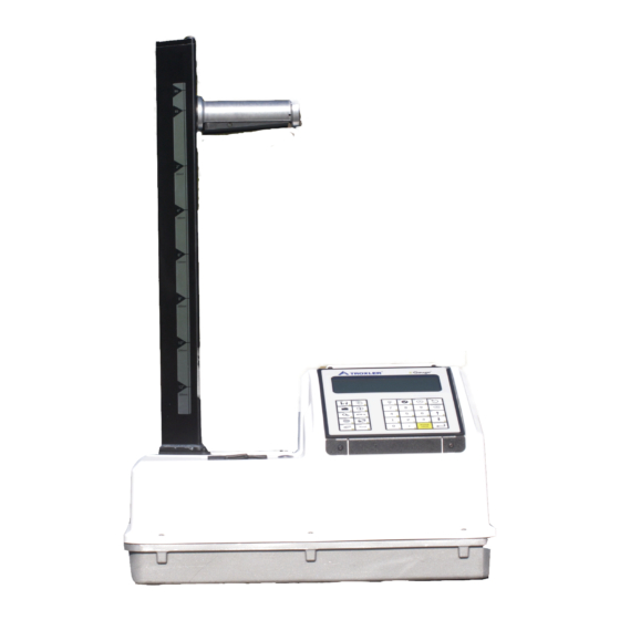
Gauge Parts and Accessories Use Figure 1 and the list below to identify the gauge and parts as they are unpacked. The Model 4540 is the portable surface density gauge containing a radioactive source, electronics, and rechargeable battery packs. The gauge serial number appears on the gauge handle, as well as on the calibration, gauge, and warranty certificates (found on the back page of this manual). -
Page 26: Figure 1. 4540 Gauge And Standard Accessories
MODEL 4540 GAUGE Figure 1. 4540 Gauge and Standard Accessories 1–6... -
Page 27: Unpacking And Inspection
Upon receipt of the gauge from the factory, perform a complete inspection and inventory. If the shipping case and/or any other part or accessory appears damaged, immediately notify the carrier and your Troxler representative 1-877-TROXLER (1- 877-876-9537). Save the box and any packing material for shipping to another location or back to the factory. -
Page 28: Chapter 2: Theory Of Operation
Chapter 2: Theory of Operation This chapter covers the following topics and tasks: ✓ Mode of operation ✓ Direct transmission ✓ Backscatter ✓ Overview of density and moisture measurements ✓ Offsets 2–2 2–1... -
Page 29: Mode Of Operation
Mode of Operation The Troxler Model 4540 Soil & Asphalt Density Gauge uses direct transmission mode and Backscatter mode. Source rod positions are described in Figure 4 on page 3–5. In the direct transmission mode, the source rod extends through the base of the gauge into a pre-drilled hole to a desired depth. -
Page 31: Moisture Measurements
Moisture Measurements The Troxler Model 6760 Moisture Probe can be supplied with the Model 4540 EGauge, it uses dielectric measurement technology to indicate the moisture content of the soil being measured. If a moisture value is known by the gauge the moisture content, percent moisture and Dry Density value can be reported and the % Proctor can also be calculated. -
Page 32: Calibration
Calibration Troxler calibrates the gauge at the factory and recommends that it is always calibrated by an authorized Troxler service center. A list of Troxler and authorized Troxler service centers are provided at the front of this manual or at: www.troxlerlabs.com/services... -
Page 33: Offsets
0.6 m (2 ft.) of a large vertical structure, perform a trench offset. A moisture probe offset should be used when the moisture content of a laboratory sample differs from the reading provided by the Troxler Moisture Probe Model 6760. Model 4540 2–5... -
Page 34: Chapter 3: Preparing For Use
Chapter 3: Preparing for Use This chapter covers the following topics and tasks: ✓ Overview of the control panel ✓ Source rod positions ✓ Daily inspection ✓ Turning the gauge on ✓ Setting up the gauge for the first time 3–1... -
Page 35: Gauge Illustration
Gauge Illustration The following figure shows the various components of the gauge that are referred to throughout this manual. Figure 2. Model 4540 Gauge Components Model 4540 3–2... -
Page 37: Control Panel
The gauge control panel shown below contains the LED screen and keypad. The keypad allows you to access the gauge software. Troxler has designed the keypad for ease of use with larger keys and anti- glare coating. Pressing a menu key activates that menu only when the Ready screen is displayed. -
Page 38: Table 1. Model 4540 Keypad Functions
Table 1. Model 4540 Keypad Functions MENU Store most recent data in the current project. STORE Display the most recent data. RECALL Select or create a project file and view, PROJECT output, or erase project data file. Displays gauge status information. STATUS... -
Page 39: Source Rod Positions
Source Rod Positions As shown below, the source rod can be placed in the SAFE position, background (BGD) position, backscatter position, or the direct transmission position. When not taking measurements, keep the source rod in the SAFE position at all times. Figure 4. -
Page 40: Charging The Gauge
Charging the Gauge The gauge is equipped with a rechargeable nickel-metal hydride (NiMH) battery pack containing five C batteries. Before turning on the gauge, charge the battery for about 3 hours. To charge the NiMH batteries: 1. Plug the AC charger or DC adapter into the charger connector under the gauge’s Port Cover (see Figure 3 on page 3–3). -
Page 41: Turning The Gauge On
Turning the Gauge On NOTE Charge the batteries for three to four hours prior to initial use. The gauge uses rechargeable NiMH batteries as a power source. Press the power switch to turn the gauge to the on position. When powered on the display screen fills with test characters before proceeding to the two-second self-test phase. - Page 42 The gauge returns to the Ready mode when the gauge is ready to proceed to another menu. The selected measurement mode (soil/asphalt) is displayed on this screen: i*-READY ASPHALT- 09-09-2020 12:21 PM Prj: TROXLER Press <START > i*-READY SOIL- 09-09-2020 12:21 PM Prj: TROXLER Press <START...
-
Page 43: Daily Inspection
To select the desired mode, press the Mode button on the keypad. Then select the appropriate mode by pressing 1 for Asphalt or 2 for Soil. Mode: ASPHALT 1. Asphalt 2: Soil Press # to Select After five hours of no activity, the gauge automatically performs a total power shutdown. -
Page 44: Selecting Measurement Options
Setting the Count Time The count time defines how long the gauge measures. Longer count times produce better measurement precision. Troxler recommends a count time of two minutes for most sample measurements. The 30 second count time should only be used when a quick measurement is required because the precision is not as good as the longer count times. - Page 45 To change the count time, press 1 at the Setup menu. The gauge displays: 1. 1 min 2. 2 min * 3. 3 min 4. 4 min 5. 30 sec Quick Rdg Select the desired count time using the corresponding number key.
- Page 46 Setting Measurement Units The gauge can display measurement results in either U.S. units pounds per cubic foot (pcf) or metric (SI) units (kg/m ). To select the units, press 3 at the Options menu. The g/cm gauge displays: - UNITS – 1.
- Page 47 Setting the Automatic or Manual Depth Mode The Model 4540 gauge offers two depth modes: Automatic and Manual. In the Automatic mode, the gauge software determines the source rod depth automatically. In the Manual mode, the operator must enter the source rod depth at a gauge prompt whenever taking a measurement.
- Page 48 Press 3 to disable the moisture input feature. Results provide wet density only. The gauge displays a confirmation message and returns to the Moisture Input menu. Setting the Measurement Order To select what order the measurements are taken, press 2 from the Options menu.
-
Page 49: Chapter 4: Using The Gauge
Chapter 4: Using the Gauge This chapter covers the following topics and tasks: ✓ Preparing a test site ✓ Taking a standard count ✓ Taking measurements ✓ Using the Recall function Model 4540 4–1... -
Page 50: Site Preparation
Site Preparation Asphalt Surface Preparation It is possible, but usually not necessary, to take direct transmission readings on asphalt. Drilling a hole in asphalt can be difficult and may require the use of a proper drill (not the drill rod) if the asphalt has cooled and hardened. Under normal conditions, a backscatter reading provides an accurate measurement of asphalt density Prepare the site as follows. -
Page 51: Figure 5. Drill Rod Positioning
WARNING Under no circumstances should you use the source rod of the gauge to drill holes. This could result in breaking or damaging the source rod or providing inaccurate readings. 4. Wearing safety glasses (or other locally approved safety devices), step on the plate and hammer the drill rod at least 50 mm (2 in.) deeper than the desired test depth. -
Page 52: Figure 6. Marking The Test Area
5. Remove the drill rod by pulling straight up and twisting the extraction tool. Do not loosen the drill rod by tapping from side to side with a hammer. This will distort the hole or cause loose material to fall into the hole. 6. -
Page 53: Taking The Standard Count
Site Requirements Troxler recommends that the standard count be performed at a levelled compacted surface, soil, or asphalt. The test site should meet the following criteria: ... - Page 54 NOTE The source rod should always be in the SAFE position when the gauge is not in use. Instructions for Taking a Standard Count The standard count consists of 2 separate 2-minute counts. The first count occurs with the handle in SAFE position. ...
- Page 55 5. Press START to begin taking the 2-minute standard count. Taking Standard Ct. Step 1 xxx s Remaining NOTE The standard and background standard must each be within 1% of the average of the last 4 counts performed and stored. If the standard count average is greater than 1%, the standard count fails, and an error code displays as shown below: Error Code#:11...
- Page 56 8. Lower the handle to the background position (first notch below SAFE). The gauge automatically checks whether the source rod is in the background position and starts the second step of the background count. If the source rod is not in the background position, and if automatic depth mode is enabled (default setting), it displays: Place the source rod to...
-
Page 57: Figure 7. Gauge Position On Soil
Figure 7. Gauge Position on Soil 12. If the first attempt fails, check items listed below and retake standard count. Press STD for the display: Standard Count DS= xxxx DSB= xxxx Take New Count? <YES> or <NO> NOTE Manual mode or auto depth sensor detects correct position. - Page 58 limits, an F displays. If you do get an F, or fail, display check for the following conditions: Is the source rod in the proper position? Are any other gauges nearby? Is the gauge seated correctly on the soil? ...
- Page 59 NOTE Compare the new standard counts to those shown in the recent calibration report The DS should fall into the range shown by month on pg. 2 of the report. The standard background count should be within 1% of that shown on the top of each page of the report. Viewing the Last Four Standard Counts 1.
- Page 60 Recording the Standard Count Troxler recommends keeping a daily log of the density and background counts (see Appendix F for a sample log). To verify gauge stability, compare the daily standard count to a reliable reference as follows: During the first four days of operation of a new or recalibrated gauge, compare the daily standard count to the factory-calibrated values.
-
Page 61: Taking Measurements
Taking Measurements The Model 4540 uses a low-activity gamma-ray source and a highly efficient gamma-ray detector. Ensure that there are no other nuclear gauges within 30 feet (10 meters) of this equipment while in use. An excess of background radiation from a nearby gauge may affect the accuracy of the reading. - Page 62 Soil Mode 1. Select the Soil mode (see page 3-8). 2. If desired, enter, change, or enable the Proctor value. Select count time and background time as described on page 3–10 and 3-11. 4. Prepare the test site and position the gauge as described on page 4–2.
- Page 63 where: Percent Proctor – Displays only if the Target function is enabled. See Chapter 6: Target Menu on page 6–1. Dry Density – density value with the moisture content removed. If a moisture measurement is not used, the value displayed will match the wet density value. Formula: (DD/Proctor Target) x 100 Wet Density –...
- Page 64 Asphalt Mode 1. Select the Asphalt mode (see page 3-8). 2. If desired, enter, change, or enable the Gmb (Marshall), Gmm value. 3. Select None for Moisture Input. 4. Select count time and background time as described on page 3–10 and 3-11.
- Page 65 where: Percent Proctor – Displays only if the Target function is enabled. See Chapter 6: Target Menu on page 6–1. Dry Density – density value with the moisture content removed. If a moisture measurement is not used, the value displayed will match the wet density value. Formula: (DD/Proctor Target) x 100 Wet Density –...
- Page 66 Reposition the rod at the correct depth. If the error continues, use the gauge in Manual Depth mode (see Setting the Automatic or Manual Depth on page 3–12) until it can be serviced by a Troxler authorized service center. In the Manual Depth mode, you will be prompted to enter the depth.
- Page 67 Press YES if conditions have not changed since performing the most recent background count. Follow the prompts on the display to complete the measurement. NOTE A background count should be performed after the density measurement on a new material and or at a new jobsite.
- Page 68 Taking a Moisture Measurement with the Moisture Probe In order to use the Moisture Probe, the Moisture Input must be set to External Sensor (default setting). See page 5–8. 1. Insert the moisture probe into the prepared hole. The hole must be at least 7 inches deep. The probe baseplate must contact have with the soil surface.
- Page 69 Entering a Moisture Value from Another Method 1. If the Moisture Input is set to Manual Input, the gauge displays: Do you know the Moisture content of the soil? Press <YES> or <NO> 2. Press YES to input the moisture percentage: %Moisture Input 0.00 Press <ENTER>...
- Page 70 Storing Measurement Data After completing a measurement and before taking another measurement, data can be stored to an active project. Refer to Chapter 7: for instructions on creating and selecting the active project. If a project is active and the Auto-Store function (see page 8–12) is enabled, press ESC...
-
Page 71: Recall
Recall To view the results of the most recent measurement, press the RECALL key from the Ready screen. The Recall function can also be used to view the gauge counts from the most recent measurement. To return to the Ready screen, press the ENTER/START key. NOTE The RECALL... -
Page 72: Chapter 5: Setup Menu
Chapter 5: Setup Menu This chapter covers the following topics and tasks: ✓ Overview of the Setup menu ✓ Setting count time and units ✓ Setting the depth mode ✓ Taking a stat test ✓ Taking a drift test ✓ Overview of optional features 5–1... -
Page 73: Count Time
Setup Menu The gauge software groups most of the setup features into one menu. To access the Setup menu, press the SETUP key. The gauge displays: ↨ -Setup- 1. Count Time 2. BGD Count Time 3. Initialize Freq. ↨ -Setup- 4. - Page 74 Count Time The gauge provides three different count times for taking measurements. To change the count time, see page 3–10. A two-minute count time is recommended for the density measurement on most materials. For the EGauges that offer the 9-12-inch depth positions, a minimum 3-minute count is required for the depths below 8 inches.
- Page 75 Background (BC) Count Time There are four options provided for background count time. Background radiation affects readings; a new background count is necessary when background environment or the material measured changes. 1. 1 min 2. 2 min 3. 3 min 4.
- Page 76 Initialize Frequency The Initialize Frequency function determines how often the gauge performs an initialization, or “warm-up,” before the measurement. Troxler recommends the default option of every 10 minutes. To access this menu, press 3 from the Setup menu. The gauge displays: 1.
-
Page 77: Moisture Input
Moisture Input To select how you want to input moisture values, press 4 from the Setup menu shown on the previous page. The gauge displays: -Moisture Method- 1. External Sensor 2. Manual Input 3. None Press 1 to use an external sensor. Choose this option to use the provided moisture probe. -
Page 78: Air Voids
% Air Voids The gauge uses the specific gravity function to calculate percent air voids and void ratio in Soil mode only. The % Voids function allows the operator to enter the specific gravity of a material and disable or enable the percent air voids display. To access the % Voids function, press 6... -
Page 79: Moisture Probe
Moisture Probe The following options are available in the Moisture Probe Menu: Moisture Probe 1. Take Measurement 2. Cal Profile 3. Probe Calibration 1. Performs a measurement with the probe. To perform a moisture measurement with the external moisture probe without pairing with a density measurement, choose option 7. - Page 80 These can be used to get a general moisture measurement; however, the user should create soil specific calibrations to accurately measure the moisture of the particular soil. Scroll down to access memory positions 1 – 6 where soil specific calibrations may be stored. To Perform a Moisture Probe Calibration To calibrate the probe to a specific soil in the field- creating a material specific profile- follow these steps:...
- Page 81 If choosing 1, the following screen will display: Select Method of Data Entry: 1. Keypad Entry 2. Gauge Derived Select 1. Keypad Entry to enter the data by hand after accumulating all information in the field (at the measurement sites) and the true % moisture (usually determined in the lab for the samples collected at these measurement sites).
-
Page 82: Stat Test
Troxler service center for assistance. For a list of Troxler and authorized Troxler service centers, refer to page iii of this manual or visit the Troxler website at: www.troxlerlabs.com/services To access the Stat Test function, press 8 at the Setup menu. The gauge displays the Stat Test menu: 1. - Page 83 Taking a Stat Test Choose an area free of other nuclear gauges or radioactive sources. Place the gauge on a level surface and ensure the source rod is in the SAFE position. To take a new stat test, press 1 at the Stat Test menu shown on the previous page, and then press ENTER/START.
-
Page 84: Drift Test
Troxler service center for assistance. For a list of Troxler and authorized Troxler service centers, refer to page iii of this manual or visit the Troxler website at: www.troxlerlabs.com/services NOTE The drift test consists of five 4-minute counts, whereas the stat test consists of twenty 1-minute counts. - Page 85 To select a menu option, press the corresponding numeric key or press ESC to return to the Setup menu. Taking a Drift Test To take a new drift test, press 1 at the Drift Test menu. Place the gauge on a level surface with the source rod in the SAFE (shielded) position, and then press ENTER/START.
- Page 86 Printing the Drift Test To print the results of the last drift test to a serial printer or computer via the gauge’s 9-pin serial port, press 3 at the Drift Test menu. The gauge prompts the operator to connect the printer to the gauge.
-
Page 87: Gps
Options The Model 4540 gauge offers the following optional features that may be added to the gauge. These features can be toggled on and off from the Options menu, accessed by pressing 5 from the Setup menu. ↨ -Options- 1. GPS 2. -
Page 88: Measurement Order
GPS receiver can receive signals from the GPS satellites (see Appendix H for more information). If the GPS does not initialize within 45 minutes, contact your Troxler representative. Measurement Order To select what order the measurements are taken, press 2... -
Page 89: Set Units
Set Units The gauge can display measurement results in either U.S. units (pcf) or metric (SI) units (kg/m or g/cm ). To change the units, see page 3–11. Depth Mode The Model 4540 gauge offers two depth modes: Automatic and Manual. - Page 90 Battery Preference To switch from NiMH battery power to the Alkaline battery backup, press 6 from the Options menu. The gauge displays: -Battery Preference- 1. Rechargeable NiMH 2. Alkaline Press 1 to select the rechargeable NiMH batteries. The gauge displays a confirmation message and returns to the Battery Preference menu.
-
Page 91: Bluetooth Mode
Bluetooth Mode Select Bluetooth Mode accessed by pressing 7 from the Options menu. -Bluetooth Mode - 1. Data Transfer 2. Moisture Probe NOTE: By default, the Bluetooth Mode is set to “2. Moisture Probe.” This setting automatically changes to “1. Data Transfer”... - Page 92 External Beeper Select External Beeper by pressing 8 from the Options menu. -External Beeper - 1. ON 2. OFF Press # to select Press 1 to select the ON. The External Beeper displays Enabled. -External Beeper - ENABLED Press 2 to select the OFF. The External Beeper displays Disabled.
-
Page 93: Chapter 6: Target Menu
Chapter 6: Target Menu This chapter covers the following topics and tasks: ✓ Overview of the Target menu ✓ Enabling and disabling the target value ✓ Storing a new target value Model 4540 6–1... -
Page 94: Target Menu
Target Menu The gauge provides the ability to enter three types of density targets values: Proctor values for soil materials and Gmb and Gmm values for asphalt materials. Four values of each type can be stored. These target values are derived from the appropriate laboratory tests and represent an optimum or maximum density for a particular material. - Page 95 NOTE The TARGET key is active only when the Ready screen is displayed. To set a new Proctor target value, press 5. Enter the new target and press ENTER. After entering the value, the gauge prompts you to store the value for later use. Select YES...
- Page 96 To set a new Gmb target value, press 5. Enter the new Gmb target value and press ENTER. After entering the value, the gauge prompts you to store the value for later use. Select YES or NO Gmb: 0.0 1.
-
Page 97: Chapter 7: Calibration Offsets
Chapter 7: Calibration Offsets This chapter covers the following topics and tasks: ✓ Overview of the offset menu ✓ Enabling density, moisture, and trench offsets Model 4540 7–1... -
Page 98: About Offsets
About Offsets The Troxler Model 4540 is factory-calibrated for typical soil materials. Gauge readings can be adjusted based on alternative density tests, such as sand cone or drive cylinder tests. This adjustment, or shift, is known as an offset. NOTE... - Page 99 To access the Offset menu, press OFFSET. The gauge displays: -Offset- 1. Density OFF 2. Trench 3. Moisture NOTE The OFFSET key is active only when the Ready screen is displayed. To select a menu option, press the corresponding number key. The remainder of this chapter details the functions available from the Offset menu.
-
Page 100: Density Offset
Density Offset To access the Density Offset functions, press 1 at the Offset menu. DENSITY OFFSET #.# pcf 1. Enable 2. Disable 3. Change Offset The gauge displays the current density offset on the second line. To enable the displayed density offset, press 1. The gauge enables the offset, displays a brief confirmation message, and returns to the Ready screen. - Page 101 To change the offset, select the sign (positive or negative) using the up and down arrows, enter the density offset value (in lb/ft ), and press ENTER/START. The gauge enables the or kg/m new density offset and returns to the Ready screen. Model 4540 7–5...
-
Page 102: Trench Offset
Trench Offset Vertical structures such as the walls of a building, trench, or ditch often “echo” gamma photons back to the gauge, which may adversely affect density measurements. Trench offsets compensate for the influence of vertical structures on measurements. Use a trench offset if taking a measurement inside a trench or within 18 inches (45 cm) of a large vertical structure. -
Page 103: Moisture Probe Offset
The moisture probe offset is only used when taking measurement readings with the Troxler Moisture Probe Model 6760 (included). To access the Moisture Offset menu, press 3 at the Offset menu shown on page 7–2. - Page 104 NOTE A moisture offset simply adds or subtracts a set value to the moisture probe reading using the enabled calibration (usually a factory calibration). The Moisture Probe Calibration (page 5–15) recalibrates the probe for that particular soil allowing a material specific profile to be created.
-
Page 105: Chapter 8: Project Data
Chapter 8: Project Data This chapter covers the following topics and tasks: ✓ Overview of the Project menu ✓ Selecting and viewing projects ✓ Creating new projects ✓ Erasing projects ✓ Outputting and printing projects ✓ Deactivating projects ✓ Using the Auto-Store feature ✓... -
Page 106: Project Menu
Project Menu The gauge can store up to 1000 readings. The Project and Store functions allow handling of measurement data. Measurement results are stored in files (memory locations) called projects, which are named by the operator. Projects are managed using the Projects menu. From this menu, the operator can select a project (make an existing project active so that additional data may be added to it), view project data, create a new project, erase projects, output project data to... -
Page 107: Select A Project
Select a Project To select an existing project, press 1 at the Projects menu shown on page 8–2. If no projects have been created, the gauge displays the error message: No projects are Stored. Press any key to continue Press any key to return to the Projects menu, and create a project as described on page 8–5. -
Page 108: View Project Data
View Project Data The gauge offers two methods of viewing data. You can either view the last measurement results using the Recall function (see page 4–20), or any measurement results, including project notes, stored in a project file using the View function available from the Projects menu. -
Page 109: Create A Project
Create a Project To create a new project, press 3 at the Projects menu. The gauge displays: Project Name <ALPHA> for Letters <ENTER> to EXIT Press the ALPHA LOCK key to enable the alphabetic keys on the gauge. When the alphabetic keys are enabled, the symbol appears in the upper right of the display, as shown above. -
Page 110: Erase Projects
Erase Projects To erase either a selected project file or all project files, press 4 at the Projects menu. The gauge displays the Erase menu: Erase: 1. One Project 2. All Projects Press # to Select To erase a single project, press 1. If more than one project has been created, the gauge displays: ↨... -
Page 111: Output Project
To output project data via the 9-pin serial port, connect a serial cable to the port. An optional serial cable, P/N 113128, is available from Troxler. Connect the serial cable to the computer’s COM port (or a printer’s serial port). -
Page 112: Table 2. Spreadsheet Column Definitions
Uploading Data to Bluetooth Devices Gauge Reader App is a useful tool for uploading project data and is available on Google Play. Spreadsheet Column Definitions Table 2. Spreadsheet Column Definitions Record Number Center Line Distance Time and Date Gmb Target Project Name Gmm Target User... -
Page 113: Set Output Destination
Set Output Destination To select the output destination, press 6 at the Projects menu. The gauge displays: Output Destination: ↨ 1. Serial Port 2. USB Printer 3. USB Storage Output Destination: ↨ 4. Bluetooth Option 1 – Serial Port Selecting Option 1 Serial Port allows the data to output to either a computer or serial printer connected to the serial port. -
Page 114: Deactivate A Project
Deactivate a Project To deactivate the current project without selecting a different one as active, press 7 at the Projects menu. The gauge deactivates the current project, displays a brief confirmation message, and returns to the Projects menu. Press ESC to return to the Ready screen. -
Page 115: Auto-Store
Auto-Store The Auto-Store function automatically stores sample data upon completion of a measurement. The data is stored under the active project, using a sequential sample ID number. When a new project is created, the sample ID number for the Auto-Store function starts at 1 and is incremented each time a new measurement is stored automatically or manually. - Page 116 No Project Data If you attempt to enable the Auto-Store function but no project has been created, the gauge displays: No Project Data Do You Want To Enable Auto-Store by Creating a Project? To return to the Projects menu without enabling the Auto- Store function, press NO.
-
Page 117: Manual Store
Manual Store After completing a measurement and before taking another one, sample data can be stored manually under the active project. Refer to pages 8–3 through 8–5 for instructions on creating and selecting the active project. To manually store measurement data, press the STORE key while data is being displayed. -
Page 118: Chapter 9: Extended Menu
Chapter 9: Extended Menu This chapter covers the following topics and tasks: ✓ Setting the date and time ✓ Setting a user ID and customer name ✓ Viewing source decay information ✓ Erasing standard counts ✓ Setting the Low Battery Warning display options ✓... -
Page 119: Extended Menu
Extended Menu To access the Extended menu, press SETUP to display the Setup menu, then press . 9. The gauge requests an access code: Input Access Code Press <ENTER> Enter the access code shown on page xv and press the ENTER/START... -
Page 121: Clock/Calendar
Clock/Calendar The Clock/Calendar function allows the operator to change the date and time, and to select the display format for each. To access the Clock/Calendar menu, press 1 at the Extended menu. The gauge displays: - Clock/Calendar ↨ 1. Change Time 2. - Page 122 ENTER/START. The gauge sets the time and returns to the Clock/Calendar menu. CHANGE DATE To change the date, press 2 at the Clock/Calendar menu. The gauge displays: 01/08/2014 mm/dd/yyyy Input Date and Press <ENTER> (Note that in this example, the time is displayed in mm/dd/yyyy format.
- Page 123 DATE FORMAT The gauge can display the date in either mm/dd/yyyy or dd/mm/yyyy format, where mm is the month, dd is the day, and yyyy is the year. To change the date format, press 4 at the Clock/Calendar menu. The gauge displays: -Date Format- 1.
- Page 124 Customer Name The gauge can store a customer name of up to 12 alphanumeric characters. To enter a customer name, press 3 at the Extended menu. The gauge displays the current customer name on the second line. Customer Name is: CUSTOMER Change Name? <YES>...
-
Page 125: Source Decay
Source Decay The strength of radioactive material is measured by its activity, or rate of decay. This activity decreases with time. The length of time it takes a given amount of radioactive material to decay to half of its original strength is referred to as the half-life. The half-life of the Cs-137 source is 30 years. -
Page 126: Erase Standard Counts
Erase Standard Counts The Erase Standard Counts function allows the operator or service technician to remove all (four) standard counts from gauge memory. To execute the Erase Standard Counts function, press 5 at the Extended menu. The gauge displays: Erase Standard Storage Bank <YES>... -
Page 127: Low Battery Warning
Low Battery Warning The Battery Status function (see page 5–12) displays the status of the battery voltage. If the battery voltage falls below a pre- determined threshold, the gauge displays a low- battery warning symbol () in the upper-right corner of the Ready screen. -
Page 128: Software Reset
Software Reset The Software Reset function sets selected user setup values (count time, measurement units, depth mode, user ID, customer name, etc.) to their factory default values. NOTE The Software Reset function does not affect the calibration constants, gauge serial number, clock and calendar settings, or projects stored in the gauge memory. -
Page 129: Show Calibration Constants
Show Calibration Constants The Show Calibration Constants menu displays current calibration constants programmed in the gauge memory. To access this function, press 9 at the Extended menu. The gauge displays: A/1: #.######### B/1: #.######### C/1: #.######### <ENTER> to Continue To return to the Extended menu, press ESC. Model 4540 9–11... -
Page 130: Test Menu
Test Menu NOTE The functions available from the Test Menu are to be used by qualified service personnel only! 9–12... -
Page 131: Troubleshooting
Appendix A: Maintenance & Troubleshooting This appendix covers the following topics and tasks: ✓ Troubleshooting and error messages ✓ Maintaining and servicing your gauge ✓ Cleaning the gauge ✓ Battery information ✓ Replacement parts list ✓ Returning the gauge for service Model 4540... - Page 132 1. Ensure that the guidelines for performing the standard count listed on page 4–5 are followed. 2. Perform the standard count again. If it still fails, contact your nearest Troxler service center or representative. No Density Readings The most likely reason for no density readings is an electronic problem, such as a failure of the detector preamplifier.
- Page 133 2. Report lost or missing radioactive sources to your state or federal radiation control agency in accordance with applicable regulatory requirements. 3. Contact the Troxler Radiation Safety Department for further advice. Gauge Readings Appear Erratic 1. Ensure that the source rod is properly positioned in the desired measurement position.
- Page 134 Short Battery Life after Recharging 1. Check that you are using the correct charger. 2. Ensure the charging icon ( ) displays on the top-right of the display. 3. NiMH batteries may be charged up to 500 full charge- discharge cycles. The batteries may be reaching end of life cycle and may need to be replaced.
- Page 135 Possible Malfunction Indicators Symptom Possible Malfunction Batteries discharge prematurely HV Board Batteries do not charge CPU Board, Preamp Board CPU Board Battery low indicator does not function correctly Beeper stops (or is erratic) CPU Board Display malfunctions CPU Board Display test Fails CPU Board Fails stability or drift tests Preamp board...
-
Page 136: Table 3. Error Messages
Error Messages The following table displays a list of the gauge error messages, as well as the possible causes and recommended solutions for each message. Table 3. Error Messages Error Message Possible Causes Solution Bad Checksum! Gauge settings and/or Set up user preferences Default Settings project data stored in (such as measurement... - Page 137 Solution Enable Manual Depth Sensor A hardware problem has depth mode. Contact 877- Error. Enable occurred with the depth TROXLER and press “2” and Manual Mode strip. TroxTechSupport@troxlerlab s.com System is unable to Initialization Error This occurs if the source initialize.
- Page 138 Ensure the source rod position matches what is shown on the screen. If problem continues, contact the Troxler Service Center. No active project! Operator tried to store Select an existing project or measurement data, but create a new project and no project is active.
-
Page 139: Batteries
7.0 V. When the NiMH batteries drop below 5.5 V, the gauge shuts off. Troxler recommends recharging the NiMH batteries. The NiMH batteries can be fully recharged in only three hours. Backup gauge power can also be supplied using the AA alkaline batteries supplied with the gauge as described. - Page 140 Battery Charging With fully charged batteries, the Model 4540 gauge remains operational for approximately one week under normal (8-hour day) conditions. If the batteries become discharged, the following message displays on the gauge: *** WARNING! *** Battery Low! When this display appears, there are a few hours remaining before the battery must be recharged.
- Page 141 Installing and Using Alkaline Batteries The Model 4540 gauge includes alkaline battery for backup use. To install the batteries: 1. Turn the gauge off. 2. Remove the two thumb screws on the battery cover. 3. Remove the black battery holder from the battery well and remove the old batteries.
-
Page 142: Mechanical Maintenance
Troxler Service Center or representative for instructions. For a list of Troxler and authorized Troxler service centers, refer to the front of this manual or visit the Troxler website at www.troxlerlabs.com Cleaning the Base and Topshell... - Page 143 CAUTION The use of any unapproved cleaning agents such as methyl-ethyl-ketones, amines, and methylene chloride can damage the topshell and voids the warranty. Model 4540 A-13...
-
Page 144: Replacement Parts
Replacement Parts This section provides a list for replacing the major parts of the gauge and purchasing accessories. Many parts can be ordered www.troxlerlabs.com from our e-commerce site at PART NO. DESCRIPTION 012754 4540 Scraper Ring 012753 4540 Snap Ring 128432.1000 4540 Plastic Topshell 128037 4540 Nameplate... - Page 145 Accessories PART NO. DESCRIPTION 128501 Shipping Case 100421 Drill Rod 128022 Scraper Plate 103680.1000 Extraction Tool 110403 AC Adapter 104156 DC Charger 128991 4540 Operator’s Manual 113128 RS-232 Cable 107480 Concrete Adapter Model 6760 Moisture Probe Model 4540 A-15...
-
Page 146: Returning The Gauge For Service
, found on the Downloads page at www.troxlerlabs.com , with each item returned for service. This information is used by Troxler shipping and service personnel to expedite the repair work. To obtain an RGA number, please call or fax the factory or branch office with your request. -
Page 147: Appendix B: Specifications
Appendix B: Specifications This appendix provides the measurement, mechanical and electrical specifications for Model 4540 gauges. Model 4540... -
Page 148: Measurement Specifications
Measurement Specifications Precision Precision is defined as one (1) standard deviation in density readings. This number is calculated by the ratio of the standard deviation in the counting rate and the slope of the calibration curve at a given density. Parameters at 6-inch depth Direct Transmission Mode 150 mm (6 inch) - Page 149 Parameters at 12-inch depth Direct Transmission Mode 300 mm (12 inch) Measurement time is 3 min; Background Time is 1 min kg/m lb/ft Density 2150 Precision ± 14 ± 0.9 Composition error ± 0 ± 0 Backscatter Mode (98%, 4 inches) Measurement Time 3 min;...
-
Page 150: Radiological Specifications
Radiological Specifications Gamma Source 3.3 MBq (90 µCi) 40% Cs-137 Source Type Sealed Source – Special Form Stainless Steel, Source Housing Encapsulated Lead and Tungsten Shielding Max. Surface Dose Rate 0.4 mrem/hr at 5 cm Shipping Case Excepted Package... -
Page 151: Electrical Specifications
Electrical Specifications Power Source(s): Main 5 C NiMH (Rechargeable Pack) batteries 5 AA alkaline batteries Backup Charge Source 12 V DC, 2A Battery Recharge Time 3 hours maximum, automatic cutoff (may be charged incrementally without damaging the batteries) Time Before 5 hours of complete Automatic Shutdown inactivity... -
Page 152: Mechanical Specifications
Mechanical Specifications Gauge Size (w/ handle) 624 H 416 L 233 W mm (24.6 H 16.4 L 9.2 W in.) Shipping Case Size 399 H 801 L 521 W mm (15.7 H 31.5 L 20.5 W in.) Weight 15.0 kg (33.2 lb.) 35.7 kg (78.70 lb.) -
Page 153: Appendix C: Transporting & Shipping
Appendix C: Transporting & Shipping This appendix contains the following topics: ✓ U.S. Shipping Requirements ✓ Accident Notification Requirements Model 4540... -
Page 154: U.s. Shipping Requirements
U.S. Shipping Requirements Although the Model 4540 gauge is exempt from radioactive material licensing requirements, it is still subject to the U.S. DOT HAZMAT regulations. Since the Model 4540 contains a small quantity of radioactive material in the form of a sealed source, it must be prepared for shipment in accordance with applicable rules and regulations governing hazardous materials. - Page 155 Markings The package must be marked as follows: UN ID number – UN 2911 Full name and address of shipper and consignee Permissible gross weight of package if this exceeds 50 kg (110 lb.) (not applicable to the Model 4540) ...
-
Page 156: Accident Notification Requirements
Accident Notification Requirements If there is a reportable incident during transportation of the gauge, the operator is required to notify, at the earliest practical moment, the U.S. DOT at 1-800-424-8802. A reportable incident is an accident that occurs during the course of transportation (including loading, unloading, and temporary storage) in which fire, breakage, spillage, or suspected contamination occurs involving the radioactive materials. - Page 157 Appendix D: Radiation Information & Safety This appendix covers the following topics and tasks: ✓ Radiological Information ✓ Cleaning the Tungsten Sliding Block ✓ Leak Testing ✓ Training ✓ Disposal ✓ Emergency Procedures ✓ Gauge Use Precautions Model 4540...
-
Page 158: Radiological Information
Radiological Information The Model 4540 contains 3.3 MBq (90 µCi) of Cesium-137 (Cs-137) in the form of a sealed source. The source is located in an extendable source rod. The source rod provides protection against release of radioactivity under normal use and likely accident conditions, including fire. - Page 159 Troxler Service Center. For a list of Troxler and authorized Troxler service centers, refer to the front of this manual or visit the Troxler website AT: www.troxlerlabs.com/services The tungsten sliding blocks may require cleaning if the source rod becomes difficult to lower into the “measure”...
-
Page 160: Figure 8. Cleaning The Tungsten Sliding Block
1. With the source rod in the SAFE (shielded) position, place the gauge on its side. 2. Clean the heads of the three screws that hold the bottom plate to the gauge base (see Figure 8). Using a Phillips screwdriver, remove the three screws and remove the plate. -
Page 161: Leak Testing
However, if you desire to perform a leak test of the Model 4540, please perform the following using the Troxler Model 3880 Leak Test Kit (P/N 102868) and accompanying instructions. 1. Write the date, gauge model number, and serial number on the sample form and label. -
Page 162: Training
USA, there is no requirement for radiological safety training to use the gauge. However, training is required to transport the gauge (DOT HAZMAT) and operate the gauge. Troxler offers training classes that meet regulatory agency training requirements for nuclear gauge users and for DOT HAZMAT . -
Page 163: Disposal
Disposal The Model 4540 contains a small radioactive source. It is recommended that users return the device to Troxler at the end of its useful life for removal and disposal of the radioactive sources in the most environmentally responsible manner. -
Page 164: Emergency Procedures
Emergency Procedures If the nuclear gauge is lost or stolen, then immediately notify the gauge owner. The gauge owner should complete the emergency contact information on the lines furnished below. This information should be readily available to the gauge operator at all times. - Page 165 NOTE The dose rate at 1 meter (3 feet) from the gauge is less than 0.01 mrem/hr. 7. If you are unable to reach the Gauge Owner, then call the Other Contact (name and number given at the beginning of this section).
-
Page 166: Gauge Use Precautions
Tampering with or modifying the gauge or removing the sealed source can be dangerous. Before shipping a gauge to Troxler for service or repair, obtain an RGA (Returned Goods Authorization) number from the Troxler Customer Service Department, as described in Appendix A. -
Page 167: Appendix E: Unit Conversion
Appendix E: Unit Conversion This chapter contains the following topics and tasks: ✓ Measurement units ✓ Radiological units Model 4540... - Page 168 The Model 4540 gauges can display measurement results in either SI (metric) units or English units. Also, HM-181 of 49 CFR changes the standard units of radioactivity in the United States from the English unit of curies (Ci) to the SI unit of becquerel (Bq).
- Page 169 Measurement Units 1 in. = 25.4 mm 1 in. = 2.54 cm 1 ft. = 30.48 cm 1 ft. = 0.3048 m 1 pcf = 16.02 kg/m 1 pcf = 1.6 10 g/cm Model 4540...
- Page 170 Radiological Units 1 rem = 0.01 Sv 1 Ci = 37 GBq 1 mCi = 37 MBq 1 Ci = 37 kBq...
-
Page 171: Appendix F: Standard Count Log
Appendix F: Standard Count Log This chapter contains the following Work Sheets: ✓ Standard Count Log ✓ Moisture Probe Offset Worksheet Model 4540... - Page 172 Standard Count Log Use the form in this appendix as a guide when recording the daily standard counts. To verify gauge stability, compare the daily standard count to the average of the last four recorded standard counts. It may be useful to copy or scan this page for future use.
- Page 173 Standard Count Log Gauge Serial Number Date Date Model 4540...
-
Page 174: Moisture Probe Offset Worksheet
Moisture Probe Offset Worksheet This worksheet is intended to assist the user in collecting the moisture probe data in the field when performing the Moisture Probe Offset (see page 5–15). It may be useful to copy or scan this page for future use. - Page 175 Moisture Probe Offset Worksheet Date Soil Jobsite Test site Test Site Test site Test Test site Test Site Site 4 True %M Test site Test Site Test site Test Test site Test Site Site 10 True %M Date Soil Jobsite Test site Test Site Test site...
-
Page 177: Appendix G: Global Positioning System (Gps
Appendix G: Global Positioning System (GPS) This appendix covers the following topics: ✓ GPS Accuracy The Model 4540 Surface Density Gauge can be equipped with an optional GPS (Global Positioning System) receiver that provides accurate information on the location (latitude and longitude) of the gauge. -
Page 178: Gps Accuracy
GPS Accuracy As described earlier, the Model 4540 gauge can be equipped with an optional GPS receiver that determines the location (latitude and longitude) of the gauge. This information is stored with each gauge measurement. The GPS receiver used in the Model 4540 has Wide Area Augmentation System (WAAS) capabilities, which provides accuracy to within 3 m (10 ft.). - Page 179 30 to 45 minutes after the gauge is powered and GPS enabled. The gauge must be positioned such that the GPS receiver can receive signals from the GPS satellites. If the GPS does not initialize within 45 minutes, contact your Troxler representative. Model 4540...
-
Page 180: Table 5. Gps Position Accuracy
Table 5. GPS Position Accuracy Quality of Accuracy Fix Quality GPS Data Latitude and longitude GPS reading Within 3 m displayed to nearest 1/100 with WAAS (10 ft.) second Latitude and longitude Within 15 m GPS reading displayed to nearest 1/10 without WAAS (50 ft.) second... -
Page 181: Index
INDEX Access code ....................xv Accessories ....................1–5 Accident notification............... B–C-4 Alkaline batteries................A–A-11 Automatic Depth mode ....................3–12 Shutdown.....................B–B-4 Automatic shutdown................3–8 Auto-Store ..................... 8–12 Batteries Alkaline ......................5–9 Battery ....................A–A-9 Alkaline use....................A–A-11 Charge ..................B–B-4, A–A-10 Charging....................A–A-10 Specifications ....................B–B-4 Status........................ - Page 182 Count time ....................5–3 Create project ..................8–5 Customer name ..................9–6 Data storage ..................4–19 Date Format ........................ 9–4 Date, changing ..................9–4 Deactivate project ................8–11 Density ...................... 2–5 Offset ........................2–5 Offset enable ....................7–4 Depth Mode ........................5–6 Detectors ....................
- Page 183 Upon receipt ....................1–7 Licensing ....................1–4 Log, standard count .................F–F-3 Low battery warning ................9–9 Maintenance Mechanical ....................A–A-12 Malfunction indicators ..............A–A-4 Manual Depth mode ....................3–12 Store ......................... 8–14 Measurement ..................4–13 Site preparation ....................4–2 Source rod positions ..................3–5 Specifications ....................B–B-2 Mechanical...
- Page 184 Parameter setup .................. 3–10 Parts Gauge ......................... 1–5 Replacement.................... A–A-14 Percent air voids .................. 5–13 Photons ..................... 2–2 Port Serial ........................8–7 USB ........................8–7 Position Safe ........................3–5 Source rod ......................3–5 Precautions .................A–D-9 Precision ....................B–B-2 Function ........................ 5–15 Print Drift test ......................
- Page 185 Safe position ................... 3–5 Sample identification (ID) number ..........8–12 Serial Port ........................8–7 Service ....................A–A-16 Service Centers ................... iii Set units ....................5–5 Setup Depth........................ 3–12 First-time ......................3–10 Measurement Units ..................3–11 Menu ........................5–2 Shipping....................C–C-1 Case ........................F–B-5 Shutdown, automatic.............
- Page 186 Store data ....................4–19 Target Menu ........................6–2 Temperature..................F–B-5 Test Drift ........................5–20 Stat ........................5–18 Theory Offset ........................2–5 Time Count ........................5–3 Format ........................ 9–4 Time, changing ..................9–3 Time, count .................... 3–10 Training ..................... 1–4 Transport case ..................F–B-5 Trench offset ..................
-
Page 187: Warranty
During the applicable warranty period, TROXLER’s obligation under this warranty shall be limited exclusively to the repair at a TROXLER facility at no charge, except for shipping to and from TROXLER’S plant, of any instrument which may prove defective under normal use and which TROXLER’s examination shall disclose to its satisfaction to be thus... - Page 188 NOTES Notes...
Need help?
Do you have a question about the EGauge Combo 4540 and is the answer not in the manual?
Questions and answers