Advertisement
Quick Links
Advertisement

Subscribe to Our Youtube Channel
Related Manuals for Rhino-Rack RBLW


Summary of Contents for Rhino-Rack RBLW
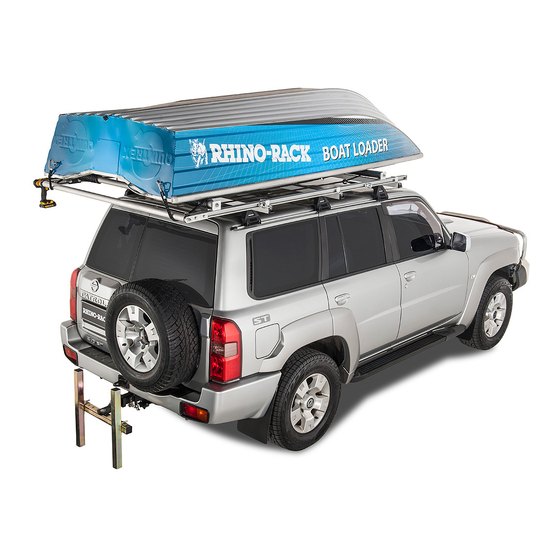
- Page 1 CONTROLLED THE BOAT LOADER FITTING INSTRUCTION. Page 1 of 28...
- Page 2 CONTROLLED DOCUMENT Preparing the boat for the eye nuts. Balance point Turn the boat over on to the gunnels, place a roller under the gunnels and parallel to the transom, roll the boat on the roller until the boat is balanced across the roller. Mark the balance point on the side of the boat adjacent to the roller (BP).
- Page 3 Transom eye nut position. Transom eye nut positions “D” and “C” generally the position of the transom eye nut: “C” = 120 mm and “D” = 150.0. Drill intersects of, “D” and “C” using a 8.5mm drill. Rear eye nut position, drill hole 8.5 mm.
- Page 4 Setting up the frame Roof racks and longitudinal bars Note: The Crossbar width must be 24cm greater than the beam of the boat. Fit the three roof racks as per the fitting instruction supplied with the roof racks. The rear roof rack must be fitted no less than 50mm from the end of the gutter. Tighten the rear roof rack. The front and center roof racks can be fitted loose, these may require repositioning later.
- Page 5 Place the top hat brackets over the longitudinal bars with the channel nuts down into the crossbars. (Refer Diagram). Top hat bracket assy. Longitudinal bar. Roof rack crossbar. Page 5 of 28...
- Page 6 Check that the passenger side bar is still parallel. Tighten only the rear crossbar top hat bracket. Note: when tightening bolts with channel nuts, ensure that the channel nut is fully located across the crossbar recess when fully tightened. (Refer Diagram). Channel nut fully located across crossbar...
- Page 7 Fitting the rope guide peg to the longitudinal bars. Slide the square channel nut into the end of the longitudinal bars to a position in between the front and middle crossbars As per the diagrams. Slide in channel nut. Screw in the rope guide peg. Position the rope guide peg between the front and middle crossbars. Tighten the rope guide peg with the eye vertical.
- Page 8 Fitting the Which and Power roller to the longitudinal bars. Winch Assemble the M10 x 20mm bolts, channel nut and washers onto the winch and Z bracket as per the diagrams, ensure that the channel nuts are loose. Z Bracket Assemble the bush and spindle onto the Z bracket, fit the flat washer, screw on the Nyloc nut and tighten.
- Page 9 Slide the power roller Z bracket onto the driver side longitudinal bar with the roller bush inwards and inline with the winch power roller shaft. Tighten the M10 x 20mm bolts ensuring that the channel nut is fully located across the bar. Page 9 of 28...
- Page 10 Page 10 of 28...
- Page 11 Clean cut end . Remove burrs and clean the cut end of the power roller, slide the rubber rings onto the roller in any position. Place the rings in hot water, this will aid the rings to slide onto the roller.
- Page 12 When fitment of the power roller is complete, rotate the winch and check that the winch and roller rotates freely. The rubber rings will be adjusted later when the ropes are fitted. Page 12 of 28...
- Page 13 Fitting the Eye bolts to the longitudinal bars. Prior to fitting the pivot roller slide the eyebolts into the longitudinal bars with the eyebolt facing inward and the channel nut fully located across the bar. Eye bolt facing inward. Slide eyebolt into bar.
- Page 14 Fitting the pivot roller to the longitudinal bars. Pivot roller brackets. Assemble the bush and spindle onto the bracket, fit the flat washer and screw on the Nyloc nut and tighten. Assemble the M10 x 20mm bolts, shake proof washer and channel nut as per the diagram, and ensure that the channel nuts are loose.
- Page 15 Marking and Cutting the roller. Align one end of the roller with the inside edge of the roller bush flange. Mark the other end of the roller adjacent to the inside edge of the driver side roller bush flange as per the diagrams. Mark roller at the roller Align roller end to bush flange for cutting.
- Page 16 Fitting the front roller to the longitudinal bars. Z brackets. Note: - The bushes for the front roller have a smaller spigot diameter. Assemble the spindle bolt, bush and bush nut, the bush nut must be positioned to allow the bush to have minimal end float and rotate freely.
- Page 17 Marking and cutting the roller. Note: - The front roller has a smaller center bore than the pivot and power rollers. Align one end of the roller with the inside edge of the Z bracket roller bush flange. Mark the other end of the roller adjacent to the inside edge of the roller bush flange as per the diagrams.
- Page 18 Position front crossbar assembly against the front roller Z brackets check that the crossbar is parallel to the rear crossbar. Position the middle crossbar, centre distance between the front and rear crossbars. Tighten the leg clamps as per the Rhino commercial roof rack fitting instruction. Tighten and check all top hat bracket bolts. BOAT LOADER LINE LAYOUT.
- Page 19 Winching Lines. Sliding lines. Tie down Transom Lines. Snap Hooks. Fitting the Rear tie down lines ( Transom lines). Cut two pieces of the hollow braided polypropylene rope to the length, equal to the distance from the transom to the Balance point plus 1000 mm, at one end splice a ring.
- Page 20 Splice ring onto the rope. Mark a length from the ring to the free end of the rope equal to the distance from the transom to the balance point, a piece of masking tape around the rope will do to mark the distance. Fitting the sliding lines to the tie down lines.
- Page 21 500 mm 250 mm Splice the free end onto the tie down line rings, at a length of 500 mm from the previously attached ring, as per the diagram. Some adjustment maybe required to this line during the loading operation. Splice the sliding line to this ring.
- Page 22 Lay 150 mm of ro p e onto the roller Tape roller full length of ro p e end. Turn the winch handle clockwise, winding the rope coils inward and over the taped rope end covering the full length of the tape, ensure there is tension on the ropes and the rope coils are tight and together. Tape over and around the rope coils for the full length of the coils ensuring overlapping of the tape, put three layers of tape over the coils, as per the diagrams.
- Page 23 Take both ends of the winch lines and pull to tension the lines. With tension on the lines turn the winch clockwise 5 turns, the lines will coil inwards. Page 23 of 28...
- Page 24 Page 24 of 28...
- Page 25 Setting up the boat and lines. Position the transom against the H frame and the boat inline with the vehicle. Transom a g ainst H frame. Clip both tie down line snap hooks onto the transom eye nuts. The bottom of the boat may be required to be lifted of the ground to attach the hooks, do one side at a time.
- Page 26 Clip the snap hooks Splice the to front eye nuts. snap hook and ring onto the winch lines. With all snap hooks connected to the eye nuts the boat should be balanced on the keel. If the winch lines are of unequal length, the boat, when in the vertical position will be leaning and will skew on the rollers. Winching the boat up and line adjustments.
- Page 27 The (BP) balance point must be at the pivot roller Sliding lines must to maximum of 50mm not be taut. below the pivot roller. If the balance point is correct, check the sliding lines, these must not be taut, if taut, un-splice the line re-adjust then splice.
- Page 28 To stow the lines on the vehicle when the boat is not loaded, snap the winch line hook to the tie down line snap hook and wind in the winch until the lines are taut. Remove the H frame. For extra safety, strap the boat to the roof rack using two Ratchet straps. Manufactured by Rhino-Rack RHINO-RACK No: RR72...
Need help?
Do you have a question about the RBLW and is the answer not in the manual?
Questions and answers