Table of Contents
Advertisement
Quick Links
Assisting the automation
Microlectra bv.
industry since 1986
User manual
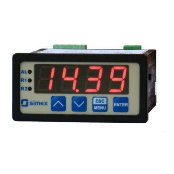
METER
SRT-73
Firmware: v.5.18 or higher
Input type: Pt100/500/1000
Two-colour display
Read the user's manual carefully before starting to use the unit or software.
Producer reserves the right to implement changes without prior notice.
Microlectra bv.
Hermanus Boerhaavestraat 6. 3261 ME Oud-Beijerland. Netherlands.
Tel 31(0)186-616290
Fax 31(0)186-610349
www.microlectra.nl
info@microlectra.nl
2013.06.06
SRT-73_INSSXEN_v.2.09.001
Advertisement
Table of Contents

Related Manuals for Simex SRT-73


Summary of Contents for Simex SRT-73
- Page 1 Assisting the automation Microlectra bv. industry since 1986 User manual METER SRT-73 Firmware: v.5.18 or higher Input type: Pt100/500/1000 Two-colour display Read the user's manual carefully before starting to use the unit or software. Producer reserves the right to implement changes without prior notice.
-
Page 2: Table Of Contents
User manual - METER SRT-73 CONTENTS 1. BASIC REQUIREMENTS AND USER SAFETY..................3 2. GENERAL CHARACTERISTICS........................4 3. TECHNICAL DATA............................4 4. DEVICE INSTALLATION..........................6 4.1. UNPACKING............................6 4.2. ASSEMBLY............................6 4.3. CONNECTION METHOD........................8 4.4. MAINTENANCE..........................13 5. FRONT PANEL DESCRIPTION........................13 6. PRINCIPLE OF OPERATION........................14 6.1. MEASUREMENT MODE........................14... -
Page 3: Basic Requirements And User Safety
User manual - METER SRT-73 Explanation of symbols used in the manual: - This symbol denotes especially important guidelines concerning the installation and operation of the device. Not complying with the guidelines denoted by this symbol may cause an accident, damage or equipment destruction. -
Page 4: General Characteristics
-100 °C to +600 °C, and input is fully linearised accordingly to PN-EN60751+A2:1999 standard. Result is showed on 4-digit LED display. The device can be equipped with one or two relay (or OC type) outputs. Device SRT-73 is equipped with RS-485 / Modbus RTU communication interface and sensor supply output. - Page 5 User manual - METER SRT-73 Display LED, 4 digit, 13mm height, two-colour (red and green) (depending on version) or (for IP 65 version) 5 digit, 9mm height, red Data memory non-volatile memory, EEPROM type Protection level (depending on display size)
-
Page 6: Device Installation
User manual - METER SRT-73 4. DEVICE INSTALLATION The unit has been designed and manufactured in a way assuring a high level of user safety and resistance to interference occurring in a typical industrial environment. In order to take full advantage of these characteristics installation of the unit must be conducted correctly and according to the local regulations. - Page 7 User manual - METER SRT-73 66,5 mm 8 mm 8 mm 8 mm 8 mm max. 5 mm 1 mm 1 mm 68 mm max. 5 mm Figure 4.1. Mounting hole dimensions: a) recommended b) allowable 92 mm 5 mm...
-
Page 8: Connection Method
User manual - METER SRT-73 91 mm Figure 4.3. Minimum distances when assembly of a number of units 4.3. CONNECTION METHOD Caution - Installation should be conducted by qualified personnel . During installation all available safety requirements should be considered. The fitter is responsible for executing the installation according to this manual, local safety and EMC regulations. - Page 9 User manual - METER SRT-73 - If the unit is equipped with housing, covers and sealing to, protecting against water intrusion, pay special attention to their correct tightening or clamping. In the case of any doubt consider using additional preventive measures (covers, roofing, seals, etc.).
- Page 10 User manual - METER SRT-73 +24V +5%, -10% RS - 485 Power max = 100mA optional) supply DATA+ (depending on version) DATA- 13 14 18 19 20 6 7 8 9 n.c. Pt100/500/1000 Pt100/500/1000 (optional) Figure 4.5. Terminals description (relay outputs)
- Page 11 User manual - METER SRT-73 13 14 FUSE FUSE Depending on version: 85...230...260V AC/DC or 19...24...50V DC; 16...24...35V AC Figure 4.7. Connection of power supply and relays Contacts of relay outputs are not equipped with spark suppressors. While use the relay outputs for switching of inductive loads (coils, contactors, power relays, electromagnets, motors etc.) it is required...
- Page 12 User manual - METER SRT-73 16 17 16 17 Logic controller LED 10 mA voltage input 24 V Figure 4.9. Example of OC-type outputs connection Temperature sensor can be connected to the device in typical 4-wire circuit (Figure 4.10a) or 3-wire circuit (Figure 4.10b).
-
Page 13: Maintenance
User manual - METER SRT-73 4.4. MAINTENANCE The unit does not have any internal replaceable or adjustable components available to the user. Pay attention to the ambient temperature in the room where the unit is operating. Excessively high temperatures cause faster ageing of the internal components and shorten the fault-free time of the unit's operation. -
Page 14: Principle Of Operation
Configuration of the device (via menu or RS-485 interface) do not stops measures . 6.2. DETECTION OF THE PEAK VALUES The SRT-73 controller is equipped with peaks detection function. It can detect a peaks of the input signal and display their values. Presets connected with this function are placed in HOLd menu (see description of HOLd menu). -
Page 15: Control Of The Relay Outputs
User manual - METER SRT-73 measure timE timE time real measurement result display value Figure 6.1. Process of peaks detection 6.3. CONTROL OF THE RELAY OUTPUTS The control of the object (measured signal) is realized via relay outputs. Front panel LEDs named R indicates the state of particular relay output. -
Page 16: One Threshold Mode
User manual - METER SRT-73 state of relay/LED SEtP or SEt2 parameter zone B zone B zone A measure HYSt parameter Figure 6.3. Two threshold control of the relay/LED outputs The relay outputs and LEDs (named R ) can be controlled depend on both - the current value and the peak value (when peak detection is active) of the input signal. - Page 17 User manual - METER SRT-73 SEtP sets a threshold of the relay, and parameter HYSt Parameter sets a hysteresis of the relay (Figure 6.4 a). The relay can change his state only when input value exceeds (over or under) border value and times (Figure 6.4) are bigger than the...
-
Page 18: Two Thresholds Mode
User manual - METER SRT-73 6.3.2. Two thresholds mode displayed value measure zone B d signal HYSt parameter SEtP or SEt2 zone A parameter HYSt parameter zone B time relay state (modE = in closed t on = 0 open... -
Page 19: Device Programming
User manual - METER SRT-73 The sequence of thresholds SEtP and SEt2 can be set in any order, due to the control of relay outputs is done depend on difference between thresholds values ( zone A ) and outside of threshold values ( zone B ). -
Page 20: Parameters Edition
User manual - METER SRT-73 [ESC/MENU] button allow user to exit present menu level and goes to upper level menu (or measurement mode). MENU After about 1 min. since last use of the buttons, device exits the menu mode and returns to the measurement mode (only if no parameters are in editing mode). -
Page 21: Menu Description
User manual - METER SRT-73 process finished. Pressing the key [ESC] after SEt? causes in cancelling of made changes and returning to menu. Functions of buttons when editing numeric and switching parameters: While editing numeric parameter: • change of current (flashing) digit •... - Page 22 User manual - METER SRT-73 SEtP - first threshold of the relay (range -999 ÷ 9999). Negative values can be input by selecting a - sign on first digit (to change value use [^] and [v] buttons). Threshold is the medium value of relay hysteresis.
-
Page 23: Inpt Menu
User manual - METER SRT-73 t on - turn on delay time, the relay is turned on with delay equal t on if the input value exceeds appropriate border value (defined with threshold and hysteresis), at least t on time. t on range 0 ÷ 99.9, defined with 0.1 sec. resolution. Unit of this parameter is set by unit parameter. -
Page 24: Bri Parameter
User manual - METER SRT-73 FiLt - this parameter sets filtration rate. It can be set to values from 0 (no filtration ) to 5 (strongest filtration time window about 2 sec). toFS - offset (expressed in 0.1°C, range ± 9.9°C.). This parameter allows shifting of measurement scale, and express value added to calculated (measured) result. -
Page 25: Hold Menu
User manual - METER SRT-73 LESS - display will change its colour after the result is lower than threshold + hysteresis SEtP - additional threshold value (range -999 ÷ 9999 ). Negative values can be input by selecting a - sign on first digit ( to change value use [^] and [v] buttons). -
Page 26: Secu Menu
User manual - METER SRT-73 7.3.6. SECu menu This menu contains presets connected with availability of other parameters: Scod - user password (4-digits number). If this parameter is set at value 0000 , user password is turned off. If the user do not remember his password, the access to the menu is possible by the one-use password . -
Page 27: Edit Parameter
User manual - METER SRT-73 - answer as quick as possible, no additional delay - answer delayed of 10, 20, 50, 100 of 200 chars respectively, where one character time depends on selected baud rate 100c 200c In the most cases parameter rESP should be set to Std (no additional delay). -
Page 28: Menu Structure
User manual - METER SRT-73 7.4. MENU STRUCTURE Measurement mode Press and hold at least 2 seconds MENU MENU 4-digit user password entering (if it is different from 0000 ) 0 _ _ _ ENTER ENTER ENTER Parameter MENU rEL1... - Page 29 User manual - METER SRT-73 See previous page ENTER ENTER Parameter MENU SCoL edition ENTER MENU C r1 C r2 C AL MENU ENTER ENTER Parameter MENU modE HOLd edition C Pr ENTER MENU timE Visible only if SEtP C Pr = on...
-
Page 30: The Alarm Led
User manual - METER SRT-73 8. THE ALARM LED Alarm LED (AL) lights in cases: exceeding of permissible measurement range detection of sensor malfunction (shortcut or break of measurement circuit) 9. THE MODBUS PRO TOCOL HANDLING Transmission parameters: 1 start bit, 8 data bits, 1 or 2 stop bit (2 bits are send, 1 and 2 bits... - Page 31 User manual - METER SRT-73 Register Write Range Register description 0 ÷ 199 Device address 20B7h Device identification code (ID) 20B3h Device identification code (IP65 version) bAud parameter in rS menu (baud rate); 0 ÷ 7 0 - 1200 baud; 1 - 2400 baud; 2 - 4800 baud; 3 - 9600 baud;...
- Page 32 User manual - METER SRT-73 Register Write Range Register description t on parameter in rEL2 menu, expressed in tenth of seconds or 0 ÷ 999 tenth of minutes depend on unit parameter - register no. 3Dh) toFF parameter in rEL2 menu, expressed in tenth of seconds 0 ÷...
-
Page 33: Transmission Errors Description
Data byte count in answer frame DATA H,L Data byte (Hi and Lo byte) CRC L,H CRC error check (Hi and Lo byte) 1. Read of the displayed value (measurement), SRT-73 device address = 01h: ADDR FUNC REG H,L COUNT H,L... - Page 34 User manual - METER SRT-73 ERROR - error code = 60h, bottom border of the measurement range is exceeded 2. Read of device ID code ADDR FUNC REG H,L COUNT H,L CRC L,H The answer: ADDR FUNC BYTE C DATA H,L...
- Page 35 User manual - METER SRT-73 5. Read of the registers 1, 2 and 3 in one message (example of reading a number of registries in one frame): ADDR FUNC REG H,L COUNT H,L CRC L,H COUNT L - the count of being read registers (max.16)
-
Page 36: Default And User's Settings List
User manual - METER SRT-73 10. DEFAULT AND USER'S SETTINGS LIST Desc. Parameter Description Default value User's value page Parameters of relay R1 operation ( rEL1 menu) SEtP Relay R1 threshold 20.0 SEt2 Relay R1 second threshold 40.0 HYSt Hysteresis of relay R1... - Page 37 User manual - METER SRT-73 Desc. Parameter Description Default value User's value page SEtP Threshold of display colour control HySt Hysteresis of display colour control Enable the use of local keyboard for CrES acknowledgement of display colour signalisation. Configuration of peaks detection function ( HOLd menu)
- Page 38 User manual - METER SRT-73...
- Page 39 User manual - METER SRT-73...
- Page 40 Microlectra bv. www.microlectra.nl info@microlectra.nl Microlectra bv. Hermanus Boerhaavestraat 6. 3261 ME Oud-Beijerland. Netherlands. Tel 31(0)186-616290 Fax 31(0)186-610349 www.microlectra.nl info@microlectra.nl...
Need help?
Do you have a question about the SRT-73 and is the answer not in the manual?
Questions and answers