Table of Contents
Advertisement
Quick Links
Firmware: v.5.11 or higher
•
Input type: pulse
•
Rotational / linear speed control
•
Read the user's manual carefully before starting to use the unit or software.
Producer reserves the right to implement changes without prior notice.
2016.08.01
User manual
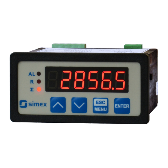
RATEMETER
STI-73
Assisting the automation
industry since 1986
STI-73_INSSXEN_v.2.07.002
Advertisement
Table of Contents

Subscribe to Our Youtube Channel
Related Manuals for Simex STI-73


Summary of Contents for Simex STI-73
- Page 1 Assisting the automation industry since 1986 User manual RATEMETER STI-73 Firmware: v.5.11 or higher • Input type: pulse • Rotational / linear speed control • Read the user's manual carefully before starting to use the unit or software. Producer reserves the right to implement changes without prior notice.
-
Page 2: Table Of Contents
User manual - RATEMETER STI-73 CONTENTS 1. BASIC REQUIREMENTS AND USER SAFETY..................3 2. GENERAL CHARACTERISTICS........................4 3. TECHNICAL DATA............................4 4. DEVICE INSTALLATION..........................6 4.1. UNPACKING............................6 4.2. ASSEMBLY............................6 4.3. CONNECTION METHOD........................8 4.4. MAINTENANCE..........................12 5. FRONT PANEL DESCRIPTION........................13 6. PRINCIPLE OF OPERATION........................14 6.1. MEASUREMENT MODE........................14... -
Page 3: Basic Requirements And User Safety
User manual - RATEMETER STI-73 Explanation of symbols used in the manual: - This symbol denotes especially important guidelines concerning the installation and operation of the device. Not complying with the guidelines denoted by this symbol may cause an accident, damage or equipment destruction. -
Page 4: General Characteristics
2. GENERAL CHARACTERISTICS The main purpose of STI-73 tachometer is measuring of the linear and rotational speed. The device can be used as frequency meter as well. Main feature of the tachometer is high precision of measurement (0.02% in full... - Page 5 User manual - RATEMETER STI-73 Indication precision Selected from range: 0 ÷ 0.00000 Rotational speed unit 1/s, 1/min. or 1/h Time between following pulses settable from 0.1 to 39.9 sec. Outputs relay: 0 or 1 NO, 1A/250V AC (cos ϕ = 1) or OC-type: 0 or 1;...
-
Page 6: Device Installation
User manual - RATEMETER STI-73 4. DEVICE INSTALLATION The unit has been designed and manufactured in a way assuring a high level of user safety and resistance to interference occurring in a typical industrial environment. In order to take full advantage of these characteristics installation of the unit must be conducted correctly and according to the local regulations. - Page 7 User manual - RATEMETER STI-73 66,5 mm 8 mm 8 mm 8 mm 8 mm max. 5 mm 1 mm 1 mm 68 mm max. 5 mm Figure 4.1. Mounting hole dimensions: a) recommended b) allowable 92 mm 5 mm...
-
Page 8: Connection Method
User manual - RATEMETER STI-73 91 mm Figure 4.3. Minimum distances when assembly of a number of units 4.3. CONNECTION METHOD Caution - Installation should be conducted by qualified personnel . During installation all available safety requirements should be considered. The fitter is responsible for executing the installation according to this manual, local safety and EMC regulations. - Page 9 User manual - RATEMETER STI-73 - Unused clamps (marked as n.c.) must not be used for connecting any connecting cables (e.g. as bridges), because this can cause damage to the equipment or electric shock. - If the unit is equipped with housing, covers and sealing packing, protecting against water intrusion, pay special attention to their correct tightening or clamping.
- Page 10 User manual - RATEMETER STI-73 6-7 mm Figure 4.4. Method of cable insulation replacing and cable terminals +24V +5%, -10% RS - 485 Power max = 100mA supply DATA+ (depending on version) DATA- 18 19 20 6 7 8 9 n.c.
- Page 11 User manual - RATEMETER STI-73 FUSE FUSE Depending on version: 85...230...260V AC/DC or 19...24...50V DC; 16...24...35V AC Figure 4.7. Connection of power supply and relays Contacts of relay outputs are not equipped with spark suppressors. While use the relay outputs for switching of inductive loads (coils, contactors, power relays, electromagnets, motors etc.) it is required...
-
Page 12: Maintenance
User manual - RATEMETER STI-73 Construction of pulse input allows connecting of inductive or optical sensor with common earth (Figure 4.9 a) or common plus (Figure 4.9 b), without additional intermediary circuits (sensor with NPN or PNP type output). 16 17 18 19 20... -
Page 13: Front Panel Description
User manual - RATEMETER STI-73 Using any other agents can cause permanent damage to the housing. Product marked with this symbol should not be placed in municipal waste. Please check local regulations for disposal and electronic products. 5. FRONT PANEL DESCRIPTION... -
Page 14: Principle Of Operation
User manual - RATEMETER STI-73 6. PRINCIPLE OF OPERATION After turning the power supply on, device ID and software version are showed on the display, next the controller goes to the measurement mode. 6.1. MEASUREMENT MODE In the measurement mode the device shows current measurement value (rotational revolution, it depends on “F or P”... -
Page 15: Detection Of The Peak Values
Configuration of the device (via menu or RS 485 interface) do not stops measures. 6.2. DETECTION OF THE PEAK VALUES The STI-73 controller is equipped with peaks detection function. It can detect a peaks of the input signal and display their values. Presets connected with this function are placed in ”HOLd”... -
Page 16: Control Of The Relay Outputs
User manual - RATEMETER STI-73 measure ”timE” ”timE” ”PEA” ”PEA” time real measurement result display value Figure 6.1. Process of peaks detection 6.3. CONTROL OF THE RELAY OUTPUTS The control of the object (measured signal) is realized via relay outputs. Front panel LEDs named „R”... -
Page 17: One Threshold Mode
User manual - RATEMETER STI-73 state of relay/LED ”SEt P” or ”SEt P2” parameter zone B zone A zone B measure ”HYSt” parameter Figure 6.3. Two threshold control of the relay/LED outputs The relay outputs and LEDs (named R) can be controlled depend on both - the current value and the peak value (when peak detection is active) of the input signal. - Page 18 User manual - RATEMETER STI-73 “SEt P” sets a threshold of the relay, and parameter “HYSt” sets a Parameter hysteresis of the relay (Figure 6.4 a). The relay can change his state only when input value exceeds (over or under) border value and times (Figure 6.4) are bigger than the...
-
Page 19: Two Thresholds Mode
User manual - RATEMETER STI-73 6.3.2. Two thresholds mode displayed value measure zone B d signal “HYSt” parameter “SEt P” or “SEt P2” zone A parameter “HYSt” parameter zone B time relay state (modE = in closed t on = 0... -
Page 20: Device Programming
User manual - RATEMETER STI-73 The sequence of thresholds “SEt P” and “SEt P2” can be set in any order, due to the control of relay outputs is done depend on difference between thresholds values ( zone A ) and outside of threshold values ( zone B ). -
Page 21: Parameters Edition
User manual - RATEMETER STI-73 Functions of the buttons while sub-menu and parameters choice: Selection of sub-menu or parameter for editing. Name of selected item (sub- menu or parameter) is displayed. Operation of [ENTER] button depend on present menu position: ENTER •... -
Page 22: Switch Parameters ("List" Type)
User manual - RATEMETER STI-73 7.2.3. Switch parameters (“LIST” type) Switch parameters can be described as a sets of values (a lists) out of which only one of the options available on the list can be selected for the given parameter. Options of switching parameter are selected using keys. - Page 23 User manual - RATEMETER STI-73 • The relay outputs and LEDs (named R) can be controlled depend on both - the current value and the peak value (when peak detection is active) of the input signal. • If device is not equipped with one or more relay outputs, menus refer to this relays are available, but apply to LED indicators only.
-
Page 24: Input" Menu
User manual - RATEMETER STI-73 “modbuS” - the relay is controlled via RS-485 interface, independently on the input signal. LEDs light when relays are closed, independently of relays' mode. • • When power supply fail, unit do not store relays state selected by RS-485 interface. - Page 25 User manual - RATEMETER STI-73 Parameter Minimum duration Permitted duty cycle ”FrEq” (Hz) of low and high states for max. frequency „10” 5 ms 5%-95% „15” 3,4 ms 5%-95% „20” 2,5 ms 5%-95% „30” 1,7 ms 5%-95% „40” 1,3 ms 5%-95% „50”...
-
Page 26: Filter" Menu
User manual - RATEMETER STI-73 “mUL” - multiplication coefficient. The value by which current measurement result is multiply to recalculate it to desired unit (e.g. linear speed); can be set in range 0 to 999999, value 0 is interpreted as 1 000 000. -
Page 27: Hold" Menu
User manual - RATEMETER STI-73 7.3.5. ”HOLd” menu This menu contains parameters connected with peak detection function. See also full description of the peak detection function in paragraph: DETECTION OF THE PEAK VALUES “modE” - the type of detected changes of the input signal, can be set to values: “PEA”... -
Page 28: Rs-485" Menu
User manual - RATEMETER STI-73 7.3.7. ”rS-485” menu This menu is connected with RS-485 interface, and sets his properties: ”Addr” - this parameter defines the address of the device, accordingly to Modbus protocol. It can be set in range from 0 to 199. If the value 0 is set then device, responds to frames with address 255 (FFh). -
Page 29: Edit T" Parameter
User manual - RATEMETER STI-73 7.3.8. ”Edit t” paramet er This parameter allows to change the edition mode of numerical parameters: ”dig” - the change to “by digit” mode, ”Slid” - slide change mode. 7.3.9. ”dEFS” parameter This setting allows to restore the factory settings of the device. To get the access to this option special password is required: „5465”, next the device displays acknowledge question... -
Page 30: Menu Structure
User manual - RATEMETER STI-73 7.4. MENU STRUCTURE Measurement mode Press and hold at least 2 seconds MENU MENU 4-digit user password entering (if it is different from „0000”) 0 _ _ _ ENTER ENTER ENTER Parameter MENU rELAy SEt P... - Page 31 User manual - RATEMETER STI-73 See previous page ENTER ENTER Parameter MENU modE HOLd edition ENTER MENU timE MENU H dis H rEL ENTER ENTER Parameter MENU SECU SEtcod edition ENTER MENU MENU Acc r ENTER ENTER Parameter MENU Addr...
-
Page 32: The Alarm Led
User manual - RATEMETER STI-73 8. THE ALARM LED The ALARM LED ( AL ) is turned on when input signal is out of the permissible frequency range. 9. EXAMPLES OF ”MUL” AND ”DIV” PARAMETERS CALCULATION 1. Let's assume that user wants to multiply rotational speed by 12.34. Then parameters “... -
Page 33: The Modbus Protocol Handling
User manual - RATEMETER STI-73 10. THE MODBUS PRO TOCOL HANDLING Transmission parameters: 1 start bit, 8 data bits, 1 or 2 stop bit (2 bits are send, 1 and 2 bits are accepted when receive), no parity control Baud rate:... - Page 34 User manual - RATEMETER STI-73 Register Write Range Register description “mUL” parameter in “inPUt” menu 0 ÷ 999999 Value 0 is interpreted as 1 000 000 “div” parameter in “inPUt” menu 0 ÷ 999999 Value 0 is interpreted as 1 000 000 0 ÷...
-
Page 35: Transmission Errors Description
User manual - RATEMETER STI-73 Register Write Range Register description “ALArmS” parameter in “rELAy” menu: 0 ÷ 2 0 - no changes; 1 - on; 2 - off 0 ÷ 999999 “SEt P2” parameter in “rELAy” menu, no decimal point included “modE”... -
Page 36: Examples Of Query/Answer Frames
User manual - RATEMETER STI-73 10.3. EXAMPLES OF QUERY/ANSWER FRAMES Examples apply for device with address 1. All values are represent hexadecimal. Field description: ADDR Device address on modbus network FUNC Function code REG H,L Starting address (address of first register to read/write, Hi and Lo byte) COUNT H,L No. - Page 37 User manual - RATEMETER STI-73 3. Change of the device address from 1 to 2 (write to reg. 20h) ADDR FUNC REG H,L DATA H,L CRC L,H DATA H - 0 DATA L - new device address (2) The answer (the same as the message):...
-
Page 38: Default And User's Settings List
User manual - RATEMETER STI-73 11. DEFAULT AND USER'S SETTINGS LIST Desc. Parameter Description Default value User's value page Parameters of relay R1 operation (“rELAy” menu) SEt P Relay first threshold 20.0 SEt P2 Relay second threshold 30.0 HYSt Hysteresis of relay... - Page 39 User manual - RATEMETER STI-73 Desc. Parameter Description Default value User's value page Permission to changes of relay R1 threshold Acc r without of the user password knowledge RS 485 interface configuration (menu “rS-485”) Addr Device address bAud Baud rate 9600 (b./sec.)
- Page 40 SIMEX Sp. z o.o. ul. Wielopole 11 80-556 Gdańsk Poland tel.: (+48 58) 762-07-77 fax: (+48 58) 762-07-70 http://www.simex.pl e-mail: info@simex.pl...
Need help?
Do you have a question about the STI-73 and is the answer not in the manual?
Questions and answers