Table of Contents
Advertisement
Quick Links
Firmware: v.5.14 or higher
•
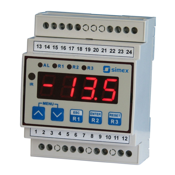
Input type: Pt100/500/1000
•
TS35 DIN rail mounted
•
Read the user's manual carefully before starting to use the unit or software.
Producer reserves the right to implement changes without prior notice.
2013.06.06
Microlectra bv.
User manual
METER
SRT-L70
Microlectra bv.
Augustapolder 12. 2992 SR Barendrecht. The Netherlands.
www.microlectra.nl
Assisting the automation
info@microlectra.nl
industry since 1986
SRT-L70_INSSXEN_v.2.07.001
Advertisement
Table of Contents

Related Manuals for Simex SRT-L70


Summary of Contents for Simex SRT-L70
- Page 1 Assisting the automation Microlectra bv. industry since 1986 User manual METER SRT-L70 Firmware: v.5.14 or higher • Input type: Pt100/500/1000 • TS35 DIN rail mounted • Read the user's manual carefully before starting to use the unit or software. Producer reserves the right to implement changes without prior notice.
-
Page 2: Table Of Contents
User manual - METER SRT-L70 CONTENTS 1. BASIC REQUIREMENTS AND USER SAFETY..................3 2. GENERAL CHARACTERISTICS........................4 3. TECHNICAL DATA............................4 4. DEVICE INSTALLATION..........................6 4.1. UNPACKING............................6 4.2. ASSEMBLY............................6 4.3. CONNECTION METHOD........................6 4.4. MAINTENANCE..........................10 5. FRONT PANEL DESCRIPTION........................11 6. PRINCIPLE OF OPERATION........................11 6.1. MEASUREMENT MODE........................11... -
Page 3: Basic Requirements And User Safety
User manual - METER SRT-L70 Explanation of symbols used in the manual: - This symbol denotes especially important guidelines concerning the installation and operation of the device. Not complying with the guidelines denoted by this symbol may cause an accident, damage or equipment destruction. -
Page 4: General Characteristics
-100 °C to +600 °C, and input is fully linearised accordingly to PN-EN60751+A2:1999 standard. Result is showed on 4-digit LED display. Thanks to modern SMPS included in SRT-L70, it can be powered from wide range of supply voltages. The device is equipped with sensor supply output, and 3 relay outputs (2 NO, and 1 NONC) which can be loaded up to max. - Page 5 User manual - METER SRT-L70 Temperature stability 50 ppm / °C Outputs relay: 3 (2 NO and 1 NONC), 8A/250V AC (cos ϕ = 1) sensor power supply: 24V +5%, -10% / max. 100 mA, stabilized, not separated from measurement inputs...
-
Page 6: Device Installation
User manual - METER SRT-L70 4. DEVICE INSTALLATION The unit has been designed and manufactured in a way assuring a high level of user safety and resistance to interference occurring in a typical industrial environment. In order to take full advantage of these characteristics installation of the unit must be conducted correctly and according to the local regulations. - Page 7 User manual - METER SRT-L70 - The power supply network cable diameter must be selected in such a way that in the case of a short circuit of the cable from the side of the unit the cable shall be protected against destruction with an electrical installation fuse.
- Page 8 User manual - METER SRT-L70 Connections of power supply voltage and measurement signals are executed using the screw connections on the top and bottom of the unit’s housing. 6-7 mm Figure 4.1. Method of cable insulation replacing and cable terminals...
- Page 9 User manual - METER SRT-L70 3 4 5 6 7 8 9 10 11 12 n.c. n.c. n.c. FUSE FUSE Depending on version: 85...230...260V AC/DC or 19...24...90V DC; 16...24...70V AC Figure 4.3. Connection of power supply and relays Contacts of relay outputs are not equipped with spark suppressors. While use the relay outputs for switching of inductive loads (coils, contactors, power relays, electromagnets, motors etc.) it is required...
-
Page 10: Maintenance
User manual - METER SRT-L70 or 3-wire circuit (Figure 4.5b). Due to precision of measurement 4-wire circuit is recommended. If 2 wire circuit is used it is recommended to connect sensor accordingly to Figure 4.5c. In this case, the resistance of wires should be as small as possible, to avoid of measurement errors. -
Page 11: Front Panel Description
User manual - METER SRT-L70 5. FRONT PANEL DESCRIPTION alarm LED indicator (AL) Thresholds exceeding LED indicators (R) infrared display receiver MENU ENTER RESET programming pushbuttons Symbols and functions of push-buttons: Symbol used in the manual: [ESC] or [ESC/R1] Functions: •... -
Page 12: Detection Of The Peak Values
Configuration of the device (via menu or RS-485 interface) do not stops measures . 6.2. DETECTION OF THE PEAK VALUES The SRT-L70 controller is equipped with peaks detection function. It can detect a peaks of the input signal and display their values. Presets connected with this function are placed in ”HOLd”... -
Page 13: Control Of The Relay Outputs
User manual - METER SRT-L70 measure ”timE” ”timE” ”PEA” ”PEA” time real measurement result display value Figure 6.1. Process of peaks detection 6.3. CONTROL OF THE RELAY OUTPUTS The control of the object (measured signal) is realized via relay outputs. Front panel LEDs named „R”... - Page 14 User manual - METER SRT-L70 state of relay/LED ”SEtP” parameter zone B zone A measure ”HYSt” parameter Figure 6.2. One threshold control of the relay/LED outputs state of relay/LED ”SEtP” or ”SEt2” parameter zone B zone B zone A measure ”HYSt”...
-
Page 15: One Threshold Mode
User manual - METER SRT-L70 6.3.1. One threshold mode Figure 6.4 presents the principle of relay outputs operation for one threshold mode, and an example values of other parameters. measured “SEtP” parameter displayed value signal (expected signal value) zone A “HYSt”... -
Page 16: Two Thresholds Mode
User manual - METER SRT-L70 (when input signal stay in zone A or zone B) are lower than parameters “t on” If t or t or “toFF”, the relay will not change his state (see points A and C, Figure 6.4 a, d, e). -
Page 17: Device Programming
User manual - METER SRT-L70 Figure 6.5 presents the principle of relay outputs operation for two thresholds mode, and an example values of other parameters. In this mode parameter “SEt2” is accessible in common with “SEtP” , this parameter describes a second threshold of the relay output. The parameters “HYSt”, “modE”, “t on”, “toFF”, “unit”... -
Page 18: Parameters Edition
User manual - METER SRT-L70 Functions of the buttons while sub-menu and parameters choice: Selection of sub-menu or parameter for editing. Name of selected item (sub- menu or parameter) is displayed. Operation of [ENTER / R2] button depend on present menu position: ENTER •... -
Page 19: Switch Parameters ("List" Type)
User manual - METER SRT-L70 a moment only, if [^] is pressed and held while button [v] is still pressed the decreasing slow down and will be kept on lower speed. Press [ENTER] at least 2 seconds to accept the changes, after that question ”Set?” is displayed, and user must to confirm (or cancel) the changes. -
Page 20: Rel1" Menu
User manual - METER SRT-L70 7.3.1. “rEL1” menu This menu allows to configure the operation mode of relays and LEDs marked „ R ” (e.g. „ R1 ”). If there are few relay outputs available, then every output has its own configuration menu (e.g. - Page 21 User manual - METER SRT-L70 - two threshold mode, relay is turned ON when the input value is bigger “out” than “bigger threshold + HYSt” and lower than “lower threshold – HYSt” , and turned on when the input signal is contained in the second zone.
-
Page 22: Inpt" Menu
User manual - METER SRT-L70 If parameter „ AL ” = „ on ”, the relay will be turned on in the critical situations, • even if his parameter “modE” = ”noAC”. 7.3.2. “inPt” menu This menu presets the measurement input: “... -
Page 23: Secu" Menu
User manual - METER SRT-L70 “H r1” ÷ “H r3” - relay/LED outputs ( R1÷R3) operation mode: ”rEAL” -relay/LED operates depend on the current value, ”HOLd” - relay/LED operates depend on the peak (drop) value. 7.3.5. ”SECu” menu This menu contains presets connected with availability of other parameters: “Scod”... -
Page 24: Edit" Parameter
User manual - METER SRT-L70 ”rESP” - this parameter defines minimal (additional) delay between the Modbus message and the answer of the device (received and sent via RS-485 interface). This additional delay allows the device to work with poor RS-converters which do not works properly on baud rates higher than 19200. -
Page 25: Menu Structure
User manual - METER SRT-L70 7.4. MENU STRUCTURE Measurement mode Press and hold both of them at least 2 sec 4-digit user password entering (if it is different from „0000”) 0 _ _ _ ENTER ENTER ENTER Parameter rEL1 SEtP... -
Page 26: The Alarm Led
User manual - METER SRT-L70 8. THE ALARM LED Alarm LED (AL) lights in cases: • exceeding of permissible measurement range • detection of sensor malfunction (shortcut or break of measurement circuit) 9. THE MODBUS PRO TOCOL HANDLING Transmission parameters: 1 start bit, 8 data bits, 1 or 2 stop bit (2 bits are send, 1 and 2 bits... - Page 27 User manual - METER SRT-L70 Register Write Range Register description 0 ÷ 199 Device address 21B4h Device identification code (ID) “bAud” parameter in “rS” menu (baud rate); 0 ÷ 7 0 - 1200 baud; 1 - 2400 baud; 2 - 4800 baud; 3 - 9600 baud;...
- Page 28 User manual - METER SRT-L70 Register Write Range Register description “toFF” parameter in “rEL2” menu, expressed in tenth of seconds 0 ÷ 999 or tenth of minutes depend on “unit” parameter - register no. 3Dh) “unit” parameter in “rEL2” menu: 0 ÷...
-
Page 29: Transmission Errors Description
Data byte count in answer frame DATA H,L Data byte (Hi and Lo byte) CRC L,H CRC error check (Hi and Lo byte) 1. Read of the displayed value (measurement), SRT-L70 device address = 01h: ADDR FUNC REG H,L COUNT H,L... - Page 30 User manual - METER SRT-L70 ERROR - error code = 60h, bottom border of the measurement range is exceeded 2. Read of device ID code ADDR FUNC REG H,L COUNT H,L CRC L,H The answer: ADDR FUNC BYTE C DATA H,L...
- Page 31 User manual - METER SRT-L70 5. Read of the registers 1, 2 and 3 in one message (example of reading a number of registries in one frame): ADDR FUNC REG H,L COUNT H,L CRC L,H COUNT L - the count of being read registers (max.16)
-
Page 32: Default And User's Settings List
User manual - METER SRT-L70 10. DEFAULT AND USER'S SETTINGS LIST Desc. Parameter Description Default value User's value page Parameters of relay R1 operation (“rEL1” menu) SEtP Relay R1 threshold 20.0 SEt2 Relay R1 second threshold 40.0 HYSt Hysteresis of relay R1... - Page 33 User manual - METER SRT-L70 Desc. Parameter Description Default value User's value page Display brightness bri6 Configuration of peaks detection function (“HOLd” menu) modE Kind of detected changes norm Minimum detected change timE Maximum time of peak displaying HdiS The type of displayed value...
- Page 34 User manual - METER SRT-L70...
- Page 35 User manual - METER SRT-L70...
- Page 36 Microlectra bv. Augustapolder 12. 2992 SR Barendrecht. The Netherlands. www.microlectra.nl info@microlectra.nl...
Need help?
Do you have a question about the SRT-L70 and is the answer not in the manual?
Questions and answers