ESAB Aristo U6 Service Manual
Hide thumbs
Also See for Aristo U6:
- Instruction manual (56 pages) ,
- Service manual (36 pages) ,
- Instruction manual (40 pages)
Table of Contents
Advertisement
Quick Links
Download this manual
See also:
Instruction Manual
Advertisement
Table of Contents

Related Manuals for ESAB Aristo U6


Summary of Contents for ESAB Aristo U6
- Page 1 Aristot Service manual 0740 800 194 090707...
-
Page 2: Table Of Contents
READ THIS FIRST ..............INTRODUCTION . -
Page 3: Read This First
READ THIS FIRST Maintenance and repair work should be performed by an experienced person, and electrical work only by a trained electrician. Use only recommended replacement parts. This service manual is intended for use by technicians with electrical/electronic training for help in connection with fault-tracing and repair. -
Page 4: Wiring Diagram
WIRING DIAGRAM The MMC module consists of three main units: 1AP1 Welding data board - Processor and CAN communication board 1AP2 Display board 1AP3 Operators control panel - Key pad with pushbuttons Wiring diagram for the U6 panel. S0740 800 194/E090707/P28 - 4 - ci08_00... -
Page 5: Description Of Operation
DESCRIPTION OF OPERATION 1AP1 Welding data board Circuit board identity The welding data board has a machine ID, a hardware ID, a unit type and a unit number. To read this you need the ESAT service kit, see page 12. The machine ID determines which type of control panel the board is intended for. -
Page 6: 1Ap1:2 Communication
1AP1:2 Communication Communication between the MMC unit and other units is via the system's CAN bus. Resistor R3 is the terminating resistor (120 Ω) for the bus. Read more about the CAN bus in the service manual for the power source. 1AP1:5 Display panel U6 The U6 display panel is backlit by parallel-connected LEDs, controlled by... -
Page 7: Fault Codes
FAULT CODES Fault log All faults that occur when using the welding equipment are documented as error messages in the fault log. When the fault log is full, the oldest message will automatically be erased when the next fault occurs. Only the most recent fault message is displayed on the control panel. -
Page 8: Fault Code Description
Fault Description Welding Cooling Power Wire Remote code data unit source feed control unit unit unit High open-circuit voltage Lost contact with the wire feed unit Lost contact with the power source Incorrect setting values in external RAM High inductance in the welding circuit Transmitter buffer overflow Receiver buffer overflow Program operating fault... - Page 9 Code Description 5 V power supply too low The unregulated power supply voltage for the processor is too low: the smoothing capacitors cannot keep the voltage up enough for the processor to continue to operate. The processor stops all normal activities, expecting to be shut down. Action: Turn off the mains power supply to reset the unit.
- Page 10 Something has prevented the processor from performing its normal tasks in the program. The program restarts automatically. The current welding process will be stopped. This fault does not disable any functions. This fault should not happen. Contact ESAB if the fault yet occurs. Stack overflow The program execution does not work.
-
Page 11: Service Instructions
SERVICE INSTRUCTIONS CAUTION ! STATIC ELECTRICITY can damage circuit boards and electronic components. Observe precautions for handling electrostatic- sensitive devices. Use proper static-proof bags and boxes. What is ESD? A sudden transfer or discharge of static electricity from one object to another. ESD stands for Electrostatic Discharge. -
Page 12: Service Aid
The software update is made from a PC, it has to be managed by a trained serviceman. For this a PC program called ESAT, ESAB Software Administration Tool, is needed. The PC is connected to the welding equipment by a cable connector and a CAN reader. From the ESAT it is possible to update the software. -
Page 13: Instructions
INSTRUCTIONS This chapter is an extract from the instruction manual for the U6 control panel. For detailed instructions, please see the instruction manual. SAFETY CAUTION! Read and understand the instruction manual before installing or operating. INTRODUCTION Control panel's working method The control panel can be said to comprise two units: the primary memory and the welding data memory. -
Page 14: Control Panel
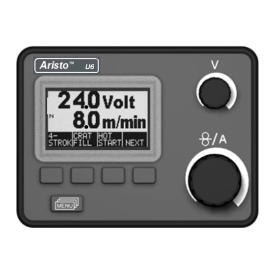
Control panel Display Knob for setting the voltage Knob for setting the wire feed speed or current Soft pushbuttons (function keys) MENU button Soft pushbuttons The functions of these buttons (i.e. what each one does) change, depending on the sub-menu shown on the display. The particular function for each button is shown by the text in the bottom line of the display, corresponding to the buttons. -
Page 15: Menus
MENUS The control panel uses several different menus: the main menu, the measurements menu, the selection menu, the process menu, the settings menu, the configuration menu and the memory menu. A startup display is also shown when starting, with information on the type of panel and the software version in use. -
Page 16: Menu Structure
Menu structure MIG/MAG 2/4 stroke MIG/MAG Puls 2/4 stroke TIG Pulsed Air gouging Craterfill Craterfill 2/4stroke 2/4 stroke Hot start Hot start Gas purg Gas purg Hot start Creep start Creep start Gas purge Gas purge Wire inch Wire inch Process menu Setting menu Configuration menu... -
Page 17: Mig/Mag Functions
MIG/MAG FUNCTIONS 2-stroke Gas pre-flow Welding Crater Gas post-flow start fill Functions when using 2-stroke control of the welding gun. In the 2-stroke control mode, pressing the welding gun trigger switch starts gas pre-flow (if used) (1) and strikes the arc. Releasing the trigger switch (2) starts crater filling (if in operation), extinguishes the arc and starts gas post-flow (if in operation). - Page 18 Crater filling Crater filling helps to avoid pores, thermal cracking and crater formation in the workpiece at the end of the weld. - Setting of crater filling time performed in the settings menu. Hot start The hot start function increases the welding current for an adjustable time at the start of welding, which reduces the risk of poor fusion at the start of the weld.
- Page 19 The synergy line package supplied with the machine is called “Standard synergic lines” and contains the 33 most frequently used synergy lines. It is also possible to order other packages of synergy lines, but these must be installed by an authorised ESAB service engineer. S0740 800 194/E090707/P28 ci08i4...
- Page 20 Inductance Higher inductance produces a more flowing weld and less spatter. Lower inductance produces a harsher sound and a stable, concentrated arc. - Setting of inductance performed in the settings menu. Gas pre-flow The gas pre-flow time is the time during which the shielding gas flows before the arc is struck.
- Page 21 Spot welding Select Spot welding when you want to “spot-weld” thin metal sheets. - Activation and setting of Spot welding is performed in the settings menu. Voltage A higher voltage gives a longer arc, with a hotter and wider weld pool. Irrespective of which menu is displayed, the setting value for the voltage can always be changed.
-
Page 22: Tig Functions
TIG FUNCTIONS 2-stroke Gas pre-flow Slope Slope down Gas post-flow 2-stroke operation of the welding gun switch button. In the 2-stroke control mode, pressing the welding gun switch button starts gas pre-flow (if used) and strikes the arc (1). The current rises to the set value (as controlled by the “slope up”... - Page 23 Lift Arc The “Lift Arc” function strikes the arc when the electrode comes into contact with the workpiece and is then lifted off. Striking the arc with the “Lift Arc” function. Step 1 shows the electrode in contact with the workpiece. The button is then pressed (Step 2), and a low current flows.
- Page 24 Gas post-flow Gas post-flow controls the time during which the shielding gas continues to flow after the arc is extinguished. - Setting of gas post-flow time performed in the settings menu. Pulse duration This is the length of time during which the pulse current is on during a pulse cycle. - Setting of pulse duration time performed in the settings menu.
-
Page 25: Mma Functions
Change of trigger data Using this function, it is possible to switch to various pre-set welding data alternatives by double-clicking on the welding torch trigger. Switching takes place between the memory positions 1, 2 and 3. If there is no data in memory position 2, switching takes place instead between positions 1 and 3. -
Page 26: General Functions
GENERAL FUNCTIONS Remote control unit Power sources with intergrated control panels should have program version 1.21 or higher, in order for the remote control to function correctly. Control panel's behaviour on connection of the remote control unit The display freezes in the menu showing when the remote control unit is connected. Measurement and setting values are updated, but only displayed in those menus in which the values can be shown. -
Page 27: Vrd (Voltage Reducing Device)
Note! The VRD function works for power sources where it is implemented. The VRD icon SPARE PARTS The spare parts list is published in a separate document that can be downloaded from the internet: www.esab.com Product Filename 0458 818 990... - Page 28 ESAB subsidiaries and representative offices Europe NORWAY Asia/Pacific Representative offices AS ESAB AUSTRIA BULGARIA CHINA Larvik ESAB Ges.m.b.H ESAB Representative Office Shanghai ESAB A/P Tel: +47 33 12 10 00 Vienna-Liesing Sofia Shanghai Fax: +47 33 11 52 03 Tel: +43 1 888 25 11...
Need help?
Do you have a question about the Aristo U6 and is the answer not in the manual?
Questions and answers