Table of Contents
Advertisement
Advertisement
Table of Contents

Related Manuals for Seiko MTP Series


Summary of Contents for Seiko MTP Series
- Page 1 MTP SERIES THERMAL PRINTER MECHANISM TECHNICAL REFERENCE U00084438003...
- Page 2 Copyright © 1995, 2003, 2005, 2011 by Seiko Instruments Inc. All rights reserved. Seiko Instruments Inc. (hereinafter referred to as “SII”) has prepared this technical reference for use by SII personnel, licensees, and customers. The information contained herein is the property of SII and shall not be reproduced in whole or in part without the prior written approval of SII.
- Page 3 PREFACE This reference manual describes the specifications and basic operating procedures for the MTP Series Thermal Printer Mechanisms. Read it thoroughly so that you are able to use the MTP Series Thermal Printer Mechanisms properly. The MTP (RoHS supporting) series has the following eight types of printers.
-
Page 4: Table Of Contents
TABLE OF CONTENTS Section Page CHAPTER 1 FEATURES CHAPTER 2 SPECIFICATIONS PART NUMBER........................2-1 GENERAL SPECIFICATIONS..................2-2 2.2.1 Character Printers ....................2-2 2.2.2 Graphic Printers ....................2-4 MOTOR DRIVER CHARACTERISTICS................2-6 TG (TACHO-GENERATOR) OUTPUT CHARACTERISTICS..........2-8 HOME SWITCH ........................2-9 THERMAL PRINT HEAD....................2-10 2.6.1 Head Specifications....................2-10 2.6.2 Head Applied Energy Correction................2-11 2.6.3 Head Activation Pulse Width .................2-12 2.6.4 Control of Printing Pulse Width ................2-13 2.6.5 Initialization......................2-14... - Page 5 Section Page CHAPTER 4 TIMING CHART TIMING CHART ........................4-1 DETAILED CHART OF PRINTING START TIMING ............4-3 CONTINUOUS PRINTING OPERATION .................4-3 4.3.1 Home Switch Signal Method .................4-3 4.3.2 Timing Signal Count Method .................4-4 CHAPTER 5 APPEARANCE AND DIMENSIONS CHAPTER 6 SAMPLE CIRCUIT BLOCK DIAGRAM CHAPTER 7 DESIGNING AND HANDLING PRECAUTIONS DESIGN PRECAUTIONS ....................7-1...
- Page 6 Section Page THERMAL PAPER TAKE-UP DEVICE ................8-6 FLEXIBLE CABLE ......................8-7 8.5.1 Connecting and Fixing the Flexible Cable Terminal ..........8-7 8.5.2 Bend Radius of Flexible Cable................8-7 REPLACEMENT OF HEAD UNIT ..................8-8 8.6.1 Removing Head Unit .....................8-8 8.6.2 Mounting the Head Unit..................8-10 TABLES Table Page...
- Page 7 Figure Page Thermal Head Control Pin Assignment (B Head-mounted Printer)........3-1 Motor and Switch Control Terminal Assignment (B Head-mounted Printer, MTP102) ..3-2 Motor and Switch Control Terminal Assignment (B Head-mounted Printer, MTP201 and MTP401) ............3-2 Thermal Head Control Terminal Assignment (G Head-mounted Printer) ......3-3 Motor and Switch Control Terminal Assignment (G Head-mounted Printer) ....3-3 Timing Chart ........................4-2 Printing Start Timing Chart ....................4-3...
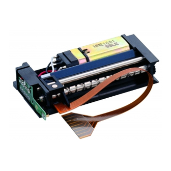
- Page 8 CHAPTER 1 FEATURES The MTP Series Line Thermal Printer Mechanism is a series of compact, thermal printers designed to meet the demand for small, low cost units. It can be used in adding machines, measuring instruments and analyzers, office machines, medical apparatus, and data terminal devices.
-
Page 9: Part Number
CHAPTER 2 SPECIFICATIONS 2.1 PART NUMBER (1) Character printers (1): Base model code (2): Characters per line* (3): Print head type used * Maximum number of characters per line based on character matrix in General specifications. (2) Graphic printers (1): Base model code (3): Print head type used (4): Maximum number of dots per row per line... -
Page 10: General Specifications
2.2 GENERAL SPECIFICATIONS 2.2.1 Character Printers Table 2-1 Character Printer Specifications Item Specifications Base model code MTP102 MTP201 MTP401 Model MTP102-13B MTP102-16B MTP201-20B MTP201-24B MTP401-40B Printing method Thermal serial dot printing Printing direction Left to right with respect to the direction the paper is fed. Dots per line 7 dots ×... - Page 11 Table 2-1 Character Printer specifications (continued) Item Specifications Base model code MTP102 MTP201 MTP401 During Current 3.2A max. printing consumption (room During temperature, paper 250mA max. 5.0V) feed Operating temperature ° 0 to 50 range Storage temperature ° −40 to 60 range Note1 Life span...
-
Page 12: Graphic Printers
2.2.2 Graphic Printers Table 2-2 Graphic Printer Specifications Item Specifications Base model code MTP201 MTP401 Model MTP201-G128 MTP201-G166 MTP401-G280 Printing method Thermal serial dot printing Printing direction Left to right with respet to the direction the paper is fed. Dots per line 8 dots ×... - Page 13 Table 2-2 Graphic Printer Specifications (continued) Item Specifications Base model code MTP201 MTP401 Current during 3.2A max. consumption printing (room during paper temperature, 250mA max feed 5.0V) º Operating temperature range 0 to 50 −40 to 60 º Storage temperature range Note1 Life span 5 hundred thousand lines (5.0V rated energy, room temperature, “8”...
-
Page 14: Motor Driver Characteristics
2.3 MOTOR DRIVER CHARACTERISTICS The motor is the power source for head movement and paper feed. Through the application of DC voltage to the motor, the head automatically moves back and forth, and paper fed on its return; therefore, there is no need to reverse the motor. 5.0 ±... - Page 15 (3) Motor stop signal Stop the motor drive signal within 1 ms after detecting a home switch “OFF” (100 to 250 μs) signal, and input a motor stop signal of at least 25 ms. 100-250 μ s Home switch signal Motor drive signal 1 ms max.
-
Page 16: Tg (Tacho-Generator) Output Characteristics
2.4 TG (TACHO-GENERATOR) OUTPUT CHARACTERISTICS The TG is a signal generator directly connected to the motor, that generates false sine waves of two cycles per 1 turn of the motor. These waves are converted by a waveform shaping circuit into rectangular wave signals, which are used as a pulse impression timing signal for the thermal head. -
Page 17: Home Switch
2.5 HOME SWITCH The home switch is a push-open type mechanical switch, which switches “OFF” when the head is at the home position (left end). The switch has two functions. The first is to detect the home position when the head stops there. Upon returning to the home position, the home switch switches from “ON” to “OFF”, and brakes are applied to stop the motion of the print head. -
Page 18: Thermal Print Head
2.6 THERMAL PRINT HEAD Because the thermal print head in the MTP Series is a thin film type with high thermal efficiency, it has an excellent print quality. The CPU determines which vertically placed heating units to energize, and drives them with the thermal head driver (transistor). -
Page 19: Head Applied Energy Correction
2.2kΩ H-COM Head drive Dot 1 2SC5585 signal 1 10kΩ 2.2kΩ Head drive Dot 2 2SC5585 signal 2 ・ ・ ・ ・ ・ 10kΩ ・ ・ ・ ・ ・ ・ ・ 2.2kΩ Head drive Dot 8 2SC5585 signal 8 10kΩ Figure 2-8 Sample Thermal Head Drive Circuit 2.6.2 Head Applied Energy Correction... -
Page 20: Head Activation Pulse Width
2.6.3 Head Activation Pulse Width To ensure high quality printing with the MTP Series, the thermal head activation pulse width must be set according to the head drive voltage and the head resistance. Pulse width calculation formula • t: Pulse width for applying rated energy (ms) R: Head resistance (Ω) -
Page 21: Control Of Printing Pulse Width
2.6.4 Control of Printing Pulse Width Superior print quality can be maintained by controlling the print pulse width by the print pulse width control circuit. This is an oscillating circuit in which the frequency varies depending upon the voltage and ambient temperature, and provides a specified pulse width by counting a certain number of pulses with the CPU. -
Page 22: Initialization
Oscillator output 4069UB 820p 100kΩ 22kΩ 150kΩ 1SS133 1740 50kΩ 22kΩ 22kΩ Print pulse width Oscillator output 1 2 3 4 5 1819 20 Head drive signal (Example: 20-pulse count) * The compensation circuits for temperature and voltage are included. * Adjust an oscillating frequency with VR to obtain the proper pulse width in 20 counts at the normal temperature. -
Page 23: Terminal Assignment
CHAPTER 3 TERMINAL ASSIGNMENT 3.1 B HEAD-MOUNTED PRINTER 3.1.1 Thermal Head Control Terminal Recommended connector: 0022023083 (MOLEX) Solder-plated surface Terminal Signal Name Function Number Dot 1 Thermal head 1st dot Dot 2 Thermal head 2nd dot Dot 3 Thermal head 3rd dot Dot 4 Thermal head 4th dot Dot 5... -
Page 24: Motor And Switch Control Terminal
3.1.2 Motor and Switch Control Terminal (1) MTP102 Recommended connector: 0022023063 (MOLEX) Solder-plated surface Terminal Signal Name Function Number Home switch, GND for V Tachogenerator, GND for V M − Motor minus Motor plus ( + 5V) Figure 3-2 Motor and Switch Control Terminal Assignment (B Head-mounted Printer, MTP102) (2) MTP201 and MTP401 Solder-plated surface Terminal... -
Page 25: G Head-Mounted Printer
3.2 G HEAD-MOUNTED PRINTER 3.2.1 Thermal Head Control Terminal Recommended connector: 0022023093 (MOLEX) Solder-plated surface Terminal Signal Name Function Number Dot 1 Thermal head 1st dot Dot 2 Thermal head 2nd dot Dot 3 Thermal head 3rd dot Dot 4 Thermal head 4th dot Dot 5 Thermal head 5th dot... -
Page 26: Timing Chart
CHAPTER 4 TIMING CHART 4.1 TIMING CHART Figure 4-1 shows the timing chart when using a B-head mounted printer. The number of the head drive signal depends on the type of thermal head mounted on the printer. - Page 27 * Signal in are issued from the circuit side. One cycle Motor drive signal Paper feeding Printing Motor current Motor stop signal Home switch signal Starting of timing signal detection TG signal Timing signal Starting of first character printing Dot 1 Dot 2 Dot 3 Head drive...
-
Page 28: Detailed Chart Of Printing Start Timing
4.2 DETAILED CHART OF PRINTING START TIMING Home switch signal TG signal Timing signal Head drive signal * Start printing from the second pulse of timing signals. Figure 4-2 Printing Start Timing Chart 4.3 CONTINUOUS PRINTING OPERATION 4.3.1 Home Switch Signal Method The print start position is determined for each line on the basis of the ON-rise of the home switch signal. -
Page 29: Timing Signal Count Method
4.3.2 Timing Signal Count Method When printing a graphic image, print a picture unit by the following method. The print start position deviation may not occur. 1. Determine the print start position of the first line by the ON-rise of the home switch signal (same as the home switch signal method). - Page 30 N is as shown below: Part Number Part Number MTP102 -13B MTP201 -G128 -16B -G166 MTP201 -20B MTP401 -G280 -24B MTP401 -40B...
-
Page 31: Appearance And Dimensions
CHAPTER 5 APPEARANCE AND DIMENSIONS Figures 5-1 to 5-5 shows the appearance and external dimensions of the MTP Series printer mechanisms. -
Page 37: Sample Circuit Block Diagram
CHAPTER 6 SAMPLE CIRCUIT BLOCK DIAGRAM Figures 6-1 and 6-2 shows the samples of the circuit block diagrams. -
Page 40: Designing And Handling Precautions
(the home switch signal detection is not executed). (3) If the MTP Series is used at extremely high temperature or at high humidity, the thermal head may be electrolytically corroded. To prevent the thermal head from being electorilytically corroded: •... - Page 41 (2) Stop the thermal head at the home position; otherwise, the platen may become deformed resulting in poor print quality. (3) Do not print without paper; otherwise, the platen or thermal head may become damaged. (4) Do not damage the platen by removing paper when a paper jam occurs. (5) Cut the edge of the paper so that the corners of the paper are square (90°);...
-
Page 42: Design Of Peripheral Devices
DESIGN OF PERIPHERAL DEVICES 8.1 DESIGN PRECAUTIONS The mounting procedure for MTP Series printers differs somewhat between the MTP102 and the other printers in the series. Mount the printer so that it is not warped or distorted in any way. -
Page 43: Mtp201 And 401 Printers
(2) When mounting without screws Using the dowels and the φ2 mm holes on the back of the printer as reference Motor for positioning, fix the printer by pressing the eaves on both sides of the upper portion of the printer (see Figure 8-3). - Page 44 (1) When mounting with screws With the φ2.2 mm holes at the corners of Tapping screw the printer as a reference for positioning, fix the printer on the printer base by tightening the tapping screws from the top of the printer (see Figure 8-5). φ2 mm Printer mounting base Figure 8-5 Mounting with Screws...
-
Page 45: Mounting The Paper Cutter
8.2 MOUNTING THE PAPER CUTTER Paper eject Design the paper cutter so that the cutter tip is direction located over the paper outlet so that it does not Paper cutter interrupt the paper flow (see Figure 8-7). Design any peripheral devices so that the paper does not re-enter the printer. -
Page 46: Mounting A Roll Holder For Head Sensitive Paper
8.3 MOUNTING A ROLL HOLDER FOR HEAD SENSITIVE PAPER Heat sensitive Printer paper roll Design the roll holder to the following specifications: Paper inlet 1) No sideways deviation between holder and inlet. 2) Less than 2 mm between holder and the sides of the roll. -
Page 47: Thermal Paper Take-Up Device
8.4 THERMAL PAPER TAKE-UP DEVICE Take into consideration the following items when designing the thermal paper take-up device. 1) After printing, the paper must be taken up without being pulled taut. 2) Even when paper guides have attached as shown below, if the thermal paper is pulled taut, correct contact between the thermal head and the thermal paper can not be obtained and printing will be adversely affected. -
Page 48: Flexible Cable
8.5 FLEXIBLE CABLE 8.5.1 Connecting and Fixing the Flexible Cable Terminal Use and FPC (Flexible Printed Circuit) connector to connect and fix the flexible cable terminal. Refer to the external view of each printer for the mounting position of the FPC connector. 8.5.2 Bend Radius of Flexible Cable Design the case of peripheral device to provide for a minimum radius of at least 5R (mm) at the point... -
Page 49: Replacement Of Head Unit
8.6 REPLACEMENT OF HEAD UNIT The model which can replace the head unit is the printer of MTP 401 series. 8.6.1 Removing Head Unit (1) Move the head carrier to position A by turning the motor gear by hand to allow easy replacement of the head unit (see figure 8-11). - Page 50 (3) Pull out the flexible cable plate in the direction shown by arrow A holding the Flexible lead edge of the plate with a finger, then wire support disengage the plate from the dowel of the plate head carrier (see figure 8-13). Dowel Head carrier frame Figure 8-13 Pulling out the Flexible Cable...
-
Page 51: Mounting The Head Unit
8.6.2 Mounting the Head Unit Head unit terminal (1) Move the head carrier to a position that permits easy replacement (see Figure 8-15). Solder-plated face (2) Insert the head unit terminal between the Guide pin platen and the guide pin and head feeding Platen screw with the soldered surface of the head unit terminal upwards (see Figure 8-15). - Page 52 (4) Slide the head unit terminal cable into the slit provided on the head carrier. Head Next, slide the head along the guide of the head carrier until it touches the guide (see Figure 8-17). Guide Head carrier frame Figure 8-17 Sliding the Head along the Guide of the Head Carrier (5) Latch the flexible cable plate to the claws of the head and push it down until engages...
Need help?
Do you have a question about the MTP Series and is the answer not in the manual?
Questions and answers