
Related Manuals for Seiko DPU-414


Summary of Contents for Seiko DPU-414
- Page 1 USER’S GUIDE Thermal Printer DPU-414 Read this manual carefully before using the printer. Keep this manual in a place where it can be accessed quickly. Seiko Instruments Inc.
- Page 2 Seiko Instruments Inc. All rights reserved. Seiko Instruments Inc. (SII) has prepared this manual for use by SII personnel, licensees, and customers. The information contained herein is the property of SII and shall not be reproduced in whole or in part without the prior written approval of SII.
- Page 3 Applicable EC Directives & standards: Directives 2004/108/EC EC Electromagnetic Compatibility Directive 2006/95/EC EC Low Voltage Directive Standards EMI: EN55022 Class B EN61000-3-2 EN61000-3-3 EMS: EN55024 EN61000-4-2, EN61000-4-3, EN61000-4-4, EN61000-4-5, EN61000-4-6, EN61000-4-8, EN61000-4-11 LVD: EN60065...
- Page 4 Federal Communications Commission (FCC) compliance statement This equipment has been tested and found to comply with the limits for a Class B digital device, pursuant to part 15 of the FCC Rules. These limits are designed to provide reasonable protection against harmful interference in a residential installation.
-
Page 5: Table Of Contents
INTRODUCTION Thank you for purchasing the DPU-414 thermal printer. This USER’S GUIDE explains how to handle DPU-414 thermal printer (hereinafter referred to as printer), specified AC adapter, specified battery pack and specified AC cable (hereinafter, omit “specified”). This USER’S GUIDE applies to the following product. -
Page 6: Safety Precautions
SAFETY PRECAUTIONS The following symbols are used in this manual in order to make use of the printer properly and prevent the printer from being damaged. Follow the instructions marked with the symbol. Severe Personal Injury or Death Failure to follow the guidelines marked with WARNING this symbol could result in severe personal injury or death. - Page 7 WARNING DO NOT use an AC adapter, battery pack or AC Cable other than that which is specified. Doing so may cause fire leading to serious accidents. DO NOT use the printer, AC adapter and AC cable in the country which has not complied with regulations.
- Page 8 CAUTION DO NOT allow metal or liquids to touch the internal parts or slot of the printer. Doing so may cause fire, electric shock, or other accidents. DO NOT disassemble or remodel the printer. DO NOT REPAIR THE PRINTER YOURSELF. Doing so may cause fire, electric shock or other accidents.
-
Page 9: Operating Precautions
For assistance with obtaining an exchange battery for this product in the USA, please contact: tpdrecycleinfo@siu-la.com Seiko Instruments USA inc. Thermal Printer Div. Thermal Paper Handling Store the thermal paper in a cool, dry, and dark place. - Page 10 Do not use chemical glue. Always use the specified thermal paper TP-411L. Installation Install the printer in a flat, stable place. Do not install the printer in the following places: • Places with strong vibration • Places with oily or iron dust •...
-
Page 11: Notations Used In This Manual
NOTATIONS USED IN THIS MANUAL The following two types of notations are used throughout this manual to denote items of caution and items to remember: NOTE This box contains items that when not followed may lead to a malfunction or to a deterioration of performance. HINT •... -
Page 12: Preparation
1 PREPARATION 1.1 Unpacking Once you have opened the carton, make sure it contains the printer and all accessories. The standard configuration contains the following 3 items: Thermal paper USER’S GUIDE/ SAFETY PRECAUTIONS Printer (CD-ROM) The option configuration contains the following items: PW-4007-EC-E PW-4007-JU1-E Specified AC Adapter... -
Page 13: Part Names
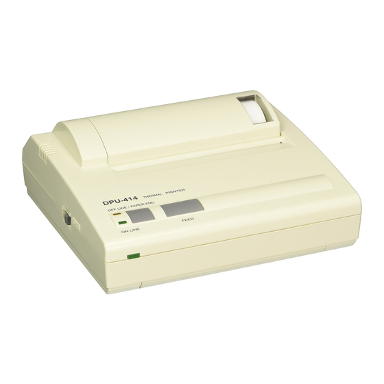
1.2 Part Names Paper cover Front Paper cover window Power Switch Power lamp Back Serial input Power supply jack Parallel input connector connector Ground screw Bottom Model plate Battery pack cover - 9 -... -
Page 14: Operation Panel
1.3 Operation Panel OFFLINE lamp ONLINE button FEED button Power Switch Power lamp ONLINE lamp 1 Power Switch Slide the power switch to turn the power on (ONLINE) or off. 2 FEED button Feeds paper when pressed in OFFLINE mode. (See the Hint on the next page). - Page 15 NOTE DO NOT press and hold the ONLINE button and FEED button for 30 seconds or more, because it will cause the DIP switches to reset and you will not be able to use the printer. Be sure the thermal head is in the home position (at the far left) before turning off the power switch.
-
Page 16: Operation
2 OPERATION 2.1 Connecting AC Adapter c Turn off the power. d Plug the DC plug on the AC adapter into the power supply jack on the printer. e Plug the AC adapter into an outlet. f Turn on the power. PW-4007-EC-E DC plug NOTE... -
Page 17: Loading The Paper
2.2 Loading the Paper Opening and Closing the Paper Cover Lightly push up on the front of the paper cover with your thumb and rotate it toward the back of the printer. Close the paper cover and push down on it to lock it into place. - 13 -... - Page 18 Loading the Paper Turn on the power. Cut the tip of the paper straight across. Paper Unused Paper can be inserted as is. Insert (See figure on right) direction Open the paper cover. Push the tip of the paper into the inlet at the bottom of the paper holder, until the auto-loader catches it and feeds about 10cm of it through the paper cutter.
-
Page 19: Setting The Dip Switches
2.3 Setting the DIP Switches The startup settings and input method can be set by the DIP switches (DIP SW). Refer to section 2.4, DIP SW Settings, for details on the different settings. Slide the power switch to OFF. Slide the power switch to ON while pressing the ONLINE button. Release the ONLINE button after a list of the current settings starts printing out. - Page 20 complete!!” is printed out and the printer returns to ONLINE mode. As soon as switch number 8 of DIP SW3 is set, the printer writes the settings to memory regardless of which button (ONLINE or FEED) is pushed. CAUTION NEVER turn the printer off while it writing the new settings to memory.
-
Page 21: Dip Sw Settings
2.4 DIP SW Settings (1) Software DIP SW1 indicates factory default setting. Switch No. Function Input Method Parallel Serial Printing speed High Auto loading Carriage Carriage CR function return and return line feed Setting Enable Disable Command 6 to 8 Print density See the table below Switch No. - Page 22 (2) Software DIP SW2 Switch No. Function Normal printing Condensed printing Print mode (80 columns) (40 columns) User-defined characters back-up Ordinary Chatacter type Special characters characters Zero font International See the table below 5 to 8 character set Switch No. Character Japanese American...
- Page 23 (3) Software DIP SW3 Switch No. Function Data bit length Eight bits Seven bits Without With Parity permission Parity condition Even H/W BUSY XON/XOFF Flow control 5 to 8 Baud rate See the table below Switch No. Baud rate 75 bps 110 bps 150 bps 300 bps...
-
Page 24: Connecting The Printer
2.5 Connecting the Printer Connection Turn off the printer and computer. Connect the printer to the computer with an interface cable. Parallel : Secure with veil lock. Serial : Secure with screws. Set the printer DIP switches to match the input method. Turn on the printer and the computer. - Page 25 Parallel Serial - 21 -...
-
Page 26: Test Print
2.6 Test Print In a test print, characters 20 to FE are printed in condensed, ordinary and double-width modes according to the international, special character and zero font settings of the DIP switches. This is followed by a small checkered pattern and solid black pattern printed dot by dot, after which the current settings are printed. -
Page 27: Hex Dump Print
2.7 HEX Dump Print Data input from the computer is printed in hexadecimal codes and in characters to allow you to check if data has been input correctly from the computer. Turn off the power. Turn the power on while pressing the Paper feed switch. Push the On-line switch when the OFFLINE lamp lights (this can be done even if the test print has started). - Page 28 2.8 Printing Turn on the power to the printer and the computer. Check that the ONLINE lamp lights. When the paper is not set, the OFFLINE lamp blinks. When the paper is loaded, the OFFLINE lamp lights. Press the On-line switch so put the printer ONLINE.
- Page 29 2.10 Handling the Battery Pack A fully charged battery pack can print about 3000 lines (40 columns of the number ”8”). The battery discharges when it is not used for a long time, therefore, immediately recharge the battery after purchase or after long periods of storage.
- Page 30 Removing the Battery Pack Remove the battery cover as shown in Figure 1. Pull out the battery pack, grab the connector with your thumb and index finger, and remove it by pulling up on it. Close the battery cover. Figure 1 Figure 2 Charging the Battery Turn the power OFF.
- Page 31 When the Battery Gets Low During Printing When the power lamp starts blinking about once every 0.5 seconds and the printer goes OFFLINE, connect the AC adapter. The ONLINE lamp will blink if there is data left in the memory buffer. In order to print the remaining data, connect the AC adapter as quickly as possible and push the ONLINE button.
-
Page 32: Printing Function
3 PRINTER FUNCTION 3.1 Buffer Full Printing The DPU-414 has a line buffer to receive data in one-line units. If data with more columns than one line is received, printing will start, even if there is no print command. This is called “Buffer full printing”. - Page 33 If an error appears: Turn off the power switch. Remove the cause. For A and B, remove any foreign objects. For C, use the printer at 0 to 40 °C (32 to 104 °F). For D, connect the AC adapter and charge the battery. Turn on the power switch.
-
Page 34: Control Code
4 CONTROL CODE The DPU-414 uses control codes to change forms and characters. The control codes are not printed. There are two types of function codes: basic function codes that can be used independently and extended function codes used with the ESC Sequence. - Page 35 ESC sequence codes Code Function ESC+ ”%” +n Select user-definable characters ESC+ ”&” +s+n Register user-definable characters ESC+ ”:” +s+SP+SP Delete user-definable characters ESC+ ”0” Set 11-dot line feed ESC+ ”2” Set 15-dot line feed ESC+ ”3” Set line feed length in half dots ESC+ ”.”...
-
Page 36: Character Code Table
5 CHARACTER CODE TABLE Japanese Character Set The following table is the Japanese character set when 0 is set to normal 0. - 32 -... - Page 37 IBM Character Set The following table is the English character set when 0 is set to normal - 33 -...
-
Page 38: Specifications
6 SPECIFICATIONS 6.1 General Specifications Printer specifications Printing method : Thermal serial dot Character mode × Total number of dots 320 dots / line × Character matrix : 9 dot high 7 dot wide Space between characters : 1dot Columns : 40 column (normal), 80 column (condensed) Printing direction : Unidirectional or bidirectional logical seek... - Page 39 Specifications of Specified AC Adapter (Option) Item JU Type EC Type Product No. PW-4007-JU1-E PW -4007-EC-E Input 100VAC to 120VAC 50Hz to 60Hz 230VAC 50/60Hz Output 7.0VDC 2.0A 6.5VDC 2.0A 104mm u 43mm u 32mm 89mm u 51mm u 28mm Dimensions Cable length : 1.85m Cable length : 1.83m...
-
Page 40: Interface Specifications
6.2 Interface Specifications Parallel (1) Specifications Data input : Eight-bit parallel (Centronics) Handshake: , BUSY, and STROBE (2) Connector signal description Pin no. Signal Function Input Data strobe STROBE DATA Carries the input data 1 when high and 0 2 to 9 Input 0 to 7 when low... - Page 41 (3) Data Input Timing (Unit: μs, typical) DATA 0 DATA 7 0.5 Min. 0.5 Min. STROBE 0.5 Min. BUSY (4) Signal Conditions Standard Item Unit Min. Typical Max. ⎯ Input : Low Level Voltage ⎯ Input : High Level Voltage ⎯...
- Page 42 ⎯ Connected to pin 4 ⎯ Not used Output Data send request ⎯ Not used Computer connections DPU-414 Computer 2 TxD 3 RxD Connected to pin 6 5 GND Connected to pin 4 7 NC 8 RTS - 38 -...
- Page 43 ! (21 : Parity error * (2A : Overrun error Turn the power off and check computer and DPU-414 DIP switch settings. NOTE Always power OFF the printer before the host computer. Powering OFF the computer before the printer may cause the printer to print several lines of "?"...
-
Page 44: Troubleshooting
7 TROUBLESHOOTING Check the following points if your printer has malfunctioned or does not operate at all. If it has still problems, call your SII representative or the branch office. If the power does not turn on (the power lamp is off) Checkpoint Action Reference... - Page 45 If the printer does not print or stops during printing Checkpoint Action Reference page Is the OFFLINE lamp The paper has run out. flashing? Load more paper. Are the ONLINE and An error has occurred. See OFFLINE lamps on? Section 3.3. Is the OFFLINE lamp on? Set printer ONLINE.
- Page 46 If the printer prints wrong characters Checkpoint Action Reference page Is interface cable connected See Section 2.5. correctly? Are the DIP switches set Set the DIP switches according to correctly? the input method. In serial input, “!”, “?”, “*” is printed for the incorrect set at DIP SW3.
-
Page 47: Caring For The Dpu-414 Printer
8 CARING FOR THE DPU-414 PRINTER If the outside of your printer gets dirty, wipe it with a soft, dry cloth. If it gets very dirty, wet a soft cloth with mild detergent diluted with water, squeeze it well, and clean the printer. - Page 48 Seiko Instruments Inc. 1-8, Nakase, Mihama-ku, Chiba-shi, Chiba 261-8507, Japan Print System Division Telephone:+81-43-211-1106 Facsimile:+81-43-211-8037 Seiko Instruments USA Inc. Thermal Printer Div. 2990 W. Lomita Blvd., Torrance CA 90505, USA Telephone:+1-310-517-7778 Facsimile:+1-310-517-8154 Seiko Instruments GmbH Siemensstrasse 9, D-63263 Neu-lsenburg, Germany Telephone:+49-6102-297-0 Facsimile:+49-6102-297-222 Seiko Instruments (H.K.) Ltd.
Need help?
Do you have a question about the DPU-414 and is the answer not in the manual?
Questions and answers