
Related Manuals for Seiko SII RP-F10 SERIES


Summary of Contents for Seiko SII RP-F10 SERIES
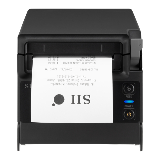
- Page 1 USER'S GUIDE Thermal Printer RP-F10 SERIES Read this USER'S GUIDE carefully before using the printer. Keep this USER'S GUIDE in a place where it can be accessed quickly.
- Page 2 (including consequential) caused by reliance on the materials presented, including but not limited to typographical, arithmetic, and listing errors. is a trademark of Seiko Instruments Inc. Bluetooth® is a registered trademark of Bluetooth SIG, Inc. The N mark is a trademark or registered trademark of NFC Forum,Inc. in the United States and in other countries.
- Page 3 Product: AC adapter PW-G2421-W1 Directive: Title 2014/30/EU EC Electromagnetic Compatibility Directive 2014/35/EU EC Low Voltage Directive 2011/65/EU (Commission Delegated Directive (EU) 2015/863) Restriction of the use of certain hazardous substances (RoHS) Directive Standards EN 55032 EN 61000-3-2 EN 61000-3-3 EN 55024 EN 62368-1 EN 50581 Federal Communications Commission (FCC) compliance statement...
-
Page 4: Table Of Contents
1. INTRODUCTION This manual describes how to handle RP-F10 series thermal printer (hereinafter referred to as printer), AC adapter and AC cable. Read through "2. SAFETY PRECAUTIONS" and "3. OPERATING PRECAUTIONS" carefully before using the products, and handle them safely and properly. Keep this manual in a place where it can be accessed quickly. -
Page 5: Safety Precautions
2. SAFETY PRECAUTIONS In this SAFETY PRECAUTIONS, the following symbols are used to ensure safe and proper use of products and prevent from damaging devices. WARNING Failure to follow the instructions marked with this symbol could result in severe personal injury or death. CAUTION Failure to follow the instructions marked with this symbol could result in minor personal injury or property damage. - Page 6 OPERATING PRECAUTIONS The "products" shall collectively mean the printer, the AC adapter and the AC cable. WARNING Never attempt the following. Failure to follow the instructions leads to fire, electric shock, or accident. DO NOT insert any foreign objects such as a piece of metal or any liquid into the products. DO NOT touch the terminals of the products, power connector, AC plug, and DC plug.
- Page 7 Procedures to take when in trouble Follow the instructions in the following cases. Failure to follow the instructions may lead fire, electric shock, or accident. Turn off the printer, and unplug the AC plug from the outlet in any of the following cases: Abnormal status continues.
-
Page 8: Operating Precautions
3. OPERATING PRECAUTIONS Be careful of the following precautions and use the products properly in order to deliver and maintain the full performance of the products. ■ Using Products Precautions for use environment Be careful not to drop or bump the products on a hard surface. ◆... - Page 9 Continuous printing and paper feeding should be performed within the following time limit since the ◆ paper feed motor heats up causing malfunction. • Ambient temperature 35°C (95°F) : 4.4 minutes or less • Ambient temperature 45°C (113°F): 3.5 minutes or less The AC adapter may get a little hot when in use.
- Page 10 Precautions for maintenance Clean the products' cases using a soft and lint-free cloth. DO NOT use alcohol or other solvent. ◆ Before using, clean the terminals using a dry, soft, and lint-free cloth when they are dirty. If the ◆ terminals are dirty, it may cause contact failure.
-
Page 11: Preparation
4. PREPARATION Make sure that the printer and its accessories are contained. Keep the package and packing materials for future transportation or long-term storage. Safety Precautions Partition Plate L Quick Start Guide Partition Plate R Printer Sample Thermal Paper... - Page 12 The available accessories are shown below. See "18. SPECIFICATIONS" and "19. ACCESSORIES AND CONSUMABLE PARTS", and be sure to purchase our specified products listed on these references. AC Cable (Above figure shows CB-JP07-20A) AC Adapter USB Cable Powered USB Cable Wall Mounting Kit...
-
Page 13: Identifying Model Type
5. IDENTIFYING MODEL TYPE The printer model is identified as follows: RP-F10-x27J1-x Model F: RP-F10 series Case color W: White K: Black Model code 27J1: Standard model Interface 2: USB + USB host 3: Ethernet + USB host 4: Bluetooth + USB host When the printer is incorporated into your equipment and then supplied electric power from the ◆... -
Page 14: Each Part Of Printer
6. EACH PART OF PRINTER RP-F10 series USB + USB host model Ethernet + USB host model Bluetooth + USB host model... - Page 15 1 POWER Switch 10 Platen The POWER Switch turns the power on or off. The platen brings the thermal paper into contact The LED lights when turning on the power. To with the thermal head. The platen rotates to feed turn off the power, hold down the switch for longer the paper.
- Page 16 ■ LED Indication Printer Status LED (Color) (Lighting Pattern) Power off Power on (print-ready) Blue Printing Green Waiting for test print Green Blink-2 Output buffer full Green Blink-1 Out-of-paper error Lime yellow Blink-1 Cover open error Lime yellow Hardware error Head temperature error Purple Voltage error...
- Page 17 ■ Error and Recovery Procedure When an error occurs, the printer stops printing operation. However, the data receiving is enabled. The table below shows errors and their recovery procedures. Priority Error Detail Recovery Procedure The printer becomes this state after releasing The return-waiting state is released Return-waiting out-of-paper error, cover...
-
Page 18: Power Connection
7. POWER CONNECTION To supply power to the printer, use the AC adapter. Be sure to see "18. SPECIFICATIONS" for the AC adapter. The AC adapter and the AC cable are optional accessories. See "18. SPECIFICATIONS" and "19. ACCESSORIES AND CONSUMABLE PARTS", and be sure to purchase our specified products listed on these references. -
Page 19: Loading Thermal Paper
8. LOADING THERMAL PAPER The printer uses the thermal paper roll (hereinafter referred to as thermal paper). Use the thermal paper with printing surface rolled outwards. The function settings of the printer differ depending on the thermal paper. See "11. FUNCTION SETTINGS"... - Page 20 Take the glued end from the thermal paper. Load the thermal paper into the paper holder. At the time, load the thermal paper direction as shown in Figure 8-3 and Figure 8-4. Top eject Front eject Printing surface Printing surface Figure 8-3 Thermal Paper Setting Direction Figure 8-4 Thermal Paper Setting Direction (Top Eject)
- Page 21 Pull the thermal paper straight. Make sure that the thermal paper does not slant. Top eject Front eject 【Correct】 【Correct】 【Incorrect】 【Incorrect】 Figure 8-5 Thermal Paper Setting State Figure 8-6 Thermal Paper Setting State (Top Eject) (Front Eject)
- Page 22 Push firmly the part indicated by the arrow in Figure 8-7 and Figure 8-8 to close the paper cover to avoid one side lock defect. After closing the paper cover, paper feed and paper cutting are performed automatically. Top eject Front eject Figure 8-7 Paper Cover (Top Eject) Figure 8-8 Paper Cover (Front Eject)
- Page 23 ■ Thermal Paper Shape Always use the specified thermal paper. See "19. ACCESSORIES AND CONSUMABLE PARTS" for details. NOTE ◆ DO NOT use the thermal paper whose end is glued, taped or folded. ◆ Use the thermal paper whose core inside diameter is 12 mm or more and whose outside diameter is 18 mm or more.
-
Page 24: Prevention And Treatment Of Paper Jam
9. PREVENTION AND TREATMENT OF PAPER JAM DO NOT touch the thermal paper while the paper is being ejected or before it is cut. Covering the paper outlet or pulling out the thermal paper when ejecting may cause a paper jam, cut failure, or line feed failure. - Page 25 ■ Cutter Error Treatment When the cutter is locked during paper cutting due to a cutter error and the paper cover does not open, recover the printer according to the following procedure. Turn off the printer. NOTE ◆ Be sure to turn off the printer before handling a cutter error. By operating the release lever repeatedly to the end while holding the paper cover, the cutter blade returns to the home position.
-
Page 26: Test Print
10. TEST PRINT The printer can perform a test print. In the test print, such as the firmware version and setting values of function settings are printed. Install the thermal paper in the printer as instructed in "8. LOADING THERMAL PAPER". Ensure that no error occurs, and then turn off the printer. - Page 27 Table 10-1 Ethernet Information Item Description MAC Address MAC Address IP Address IP Address Subnet Mask Subnet Mask GateWay Address Gateway Address DHCP Client Selected DHCP Client Mode Physical Layer Selected Communication Speed and Communication Mode Figure 10-2 Test Print Sample (Ethernet + USB Host Model)
- Page 28 Table 10-2 Bluetooth Information Item Description Auto Connection Selected iOS Auto Connection Security Mode Selected Security Mode Inquiry Response Selected Inquiry Response AssocModel Selected Associetion Model Printer Name Bluetooth Device Name Address Bluetooth Address Figure 10-3 Test Print Sample (Bluetooth + USB Host Model)
-
Page 29: Function Settings
11. FUNCTION SETTINGS This printer can set various functions according to use conditions and intended use. The setting contents are stored in the Memory Switch (hereinafter referred to as MS) in the FLASH memory mounted in the printer, and it is possible to set MS by using the switches or command input. This section describes the setting procedure by using the switches. - Page 30 A message for selecting the function assigned to the selected MS is printed as a sample shown in Figure 11-3. Press the FEED Switch the number of times corresponding to the selected function number, and then press the POWER Switch. [Function selection of MS1] 0 : Return to MS selection 1 : Standby LED...
-
Page 31: Connecting To Host Device
12. CONNECTING TO HOST DEVICE The printer supports the USB interface, the Ethernet interface and the Bluetooth interface. The available interface varies depending on the model, order the model of interface method to use from the following. USB + USB host model (RP-F10-x27J1-2) : USB interface Ethernet + USB host model (RP-F10-x27J1-3) : Ethernet interface... - Page 32 Figure 12-2 Locking of Printer and USB Cable Figure 12-3 Printer and Ethernet Cable Connection NOTE ◆ When connecting each interface cable to the interface connector, push the plug to the end. ◆ NEVER connect a USB cable or Ethernet cable to the drawer kick connector. ◆...
- Page 33 ■ Bluetooth Interface Turn on the printer and pair it with the host device. In addition, by using the NFC (Near Field Communication Technology) tag built in the printer, automatic pairing between an NFC-enabled Android terminal and a printer is possible. NOTE ◆...
-
Page 34: Connecting To Peripheral Device
13. CONNECTING TO PERIPHERAL DEVICE This printer can be used by connecting the drawer and our specified accessories to the specified connector. ■ Drawer Connection Ensure that the printer is off. Plug the drawer kick cable to the drawer kick connector on the back side of the printer. Turn on the printer. - Page 35 ■ External Buzzer Connection Ensure that the printer is off. Plug one plug of the modular cable to the connector of external buzzer. Figure 13-2 External Buzzer and Modular Cable Connection Plug the other side plug of the modular cable to the drawer kick connector on the back side of the printer.
- Page 36 Figure 13-4 External Buzzer Installing Position Example (Top Eject) Figure 13-5 External Buzzer Installing Position Example (Front Eject) NOTE ◆ Before pasting the double-sided tape, wipe with like a dirt-free cloth so that there is no dirt or foreign matter on the pasting position.
- Page 37 ■ USB Host Interface Connection Ensure that the printer is off. Connect the plug of USB host interface cable to the USB host connector on the back side of the printer. Turn on the printer. Figure 13-6 Printer and USB Cable (USB Host) Connection NOTE ◆...
-
Page 38: Settings When Using 58Mm Paper Width
14. SETTINGS WHEN USING 58mm PAPER WIDTH Ensure that the printer is off. Operate the release lever to open the paper cover. Put the attached partition plate L and partition plate R into the paper holder with slanting position as shown in Figure 14-1. - Page 39 Put the hook which is located on the upper side of the partition plate L and partition plate R on the hole of paper holder as shown in Figure 14-3. Figure 14-3 Partition Plate Installation (3) Push the partition plate L and partition plate R to the direction of the arrow shown in Figure 14-4 with placing them along the side surface of the paper holder, and then put the projection which is located at the bottom of the partition plate in the hole of the paper holder.
- Page 40 Turn the printer over, and make sure that the projection of the partition plate L and partition plate R are fit properly into the hole of the paper holder (the arrow shown in Figure 14-5). Figure 14-5 Partition Plate Installation Check Refer to “18.
-
Page 41: Installation Of Accessories
15. INSTALLATION OF ACCESSORIES ■ Wall Mounting Kit (WLK-B01-1) Preparation Make sure that the product and its accessories are contained. Printer Bracket Wall Hanging Bracket Printer Attachment Screw 4 Pieces Wall Hanging Bracket (Tapping Screw 3×6) Attachment Screw 6 pieces (Wood Screw 3.8×18) Figure 15-1 Wall Mounting Kit (WLK-B01-1) - Page 42 Installation of Printer Bracket Firmly attach printer bracket with 4 printer attachment screws as shown in Figure 15-2. The tightening torque should be 39.2 cN•m (4 kgf•cm). Figure 15-2 Installation of Printer Bracket NOTE ◆ Before installing, ensure that the printer is off. ◆...
- Page 43 Installation of Wall Hanging Bracket Fix the wall hanging bracket to the mounting surface, and then fix it firmly with 6 wall hanging bracket attachment screws. WLK-B01-1 is designed to be installed on a wall. After installation, make sure that the wall hanging bracket is fixed on the wall securely without rattle. NOTE ◆...
-
Page 44: Printer Maintenance
16. PRINTER MAINTENANCE The thermal head of the printer does not require user maintenance. When paper powder accumulates, cleaning the thermal head can maintain the print quality for an extended period of time. ■ Cleaning Thermal Head / Platen / Rubber Feet Turn off the printer. -
Page 45: Troubleshooting
17. TROUBLESHOOTING Check the following points before requesting for repair: ■ The power does not turn on • Is the specified AC adapter being used? • Are the AC cable and the AC adapter connected correctly? • Are the AC adapter and the printer connected correctly? ■... -
Page 46: Specifications
18. SPECIFICATIONS ■ Printer Specifications Item Specification Model RP-F10 Printing method Thermal printing Number of characters per line Paper width 80 mm: 24 dots × 12 dots 48 digits (42 digits 16 dots × 8 dots 72 digits (64 digits Paper width 58 mm: 24 dots ×... - Page 47 ■ AC Adapter Specifications (Specified Accessories) Item Specification Model PW-G2421-W1 Input voltage AC100 to 240 V, 50/60 Hz Rated output DC24.0 V, 2.1 A Dimensions (W × D × H) 120 mm × 52.5 mm × 32.5 mm* Mass Approx. 260 g *: Excluding the cable.
- Page 48 ■ Sale Destinations Sale destinations for the printer and specified accessories are listed below. : Sale Destinations RP-F10 Country/Region AC Adapter AC Cable (Bluetooth (Other models) model) CB-JP07-20A Japan CB-JP08-20A EU (except UK), CB-CE04-20A EFTA CB-CE05-20A Turkey ...
-
Page 49: Accessories And Consumable Parts
19. ACCESSORIES AND CONSUMABLE PARTS ■ Specified Accessories Name Model AC adapter PW-G2421-W1 AC cable CB-JP07-20A CB-JP08-20A CB-US05-20A CB-US06-20A CB-CE04-20A CB-CE05-20A CB-UK03-20A CB-UK04-20A External buzzer BZR-A01-1 Wall mounting kit WLK-B01-1 USB cable IFC-U02-2 Powered USB cable IFC-V01-1 *: The shape of an outlet differs by country. Confirm it before using. ■... -
Page 50: Ms Settings List
20. MS SETTINGS LIST : Default value General Setting 1 Value Function Fixed 1-1 to 3 Reserved 00B:Aqua 01B:Green Standby LED Selection 1-4 to 5 10B:Off (Standby LED) 11B:Blue Reserved Fixed Auto Activation by AC Selection Disable Enable (Auto Activation by AC) POWER Switch Function Selection Enable Disable... - Page 51 General Setting 3 (External Buzzer Setting When Cut Process Completes) Value Function 00B:None Buzzer Count Selection 01B:Once 3-1 to 2 (Buzzer Count) 10B:Thrice 11B:Five Times 00B:Pattern1 Buzzer Pattern Selection 01B:Pattern2 3-3 to 4 (Buzzer Pattern) 10B:Pattern3 11B:Pattern4 Buzzer Volume Selection Loud (Buzzer Volume) 3-6 to 8...
- Page 52 General Setting 5 Value Function Automatic Status Response Selection Enable Disable (Auto Status Back) Initialized Response Selection Enable Disable (Init. Response) Data Discard Selection When Error Occurs Enable Disable (Error Through) Data Discard Selection When Output Buffer Enable Disable Full Occurs (Response Data Discarding) Reserved Fixed...
- Page 53 General Setting 7 Value Function 00000000B: Standard 00000001B: TP50KR-2Y 00000010B: PD160R Thermal Paper Selection 00000011B: TF60KS-E 7-1 to 8 (Thermal Paper) 00000100B: P220VBB-1 00000101B: Alpha400-2.1 00000110B: KT48FA Other than those above: Prohibition General Setting 13 Value Function Kanji Code System Selection 13-1 Shift-JIS Code JIS Code...
- Page 54 International Character Setting Value Function 00000000B: USA 00000001B: France 00000010B: Germany 00000011B: UK 00000100B: Denmark I 00000101B: Sweden 00000110B: Italy International Character Setting 00000111B: Spain (International Character) 00001000B: Japan 00001001B: Norway 00001010B: Denmark II 00001011B: Spain II 00001100B: Latin America 00010001B: Arabia Other than those above: Prohibition Character Code Table Setting...
- Page 55 General Setting 17 Value Function 00B: Mode1 01B: Mode2 Paper Saving Setting 17-1 to 2 (Paper Saving) 10B: Mode3 11B: Disable Feed Backward Setting After Paper 17-3 Cutting Enable Disable (Backfeed After Cut) 17-4 to 8 Reserved Fixed General Setting 18 (External Buzzer Setting With Commands) Value Function 00B: None...
- Page 56 Seiko Instruments Inc. 1-8, Nakase, Mihama-ku, Chiba-shi, Chiba 261-8507, Japan Print System Division Telephone:+81-43-211-1106 Facsimile:+81-43-211-8037 Seiko Instruments USA Inc. Thermal Printer Div. 21221 S. Western Avenue, Suite 250, Torrance, CA 90501, USA Telephone:+1-310-517-7778 Facsimile:+1-310-517-7779 Seiko Instruments GmbH Siemensstrasse 9, D-63263 Neu-lsenburg, Germany Telephone:+49-6102-297-0 Facsimile:+49-6102-297-222 info@seiko-instruments.de...
Need help?
Do you have a question about the SII RP-F10 SERIES and is the answer not in the manual?
Questions and answers