Table of Contents
Advertisement
Advertisement
Table of Contents

Related Manuals for Seiko DPU-414


Summary of Contents for Seiko DPU-414
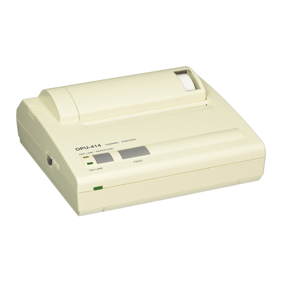
- Page 1 DPU-414 SERIAL THERMAL PRINTER SERVICE MANUAL U00100139501 Seiko Instruments Inc.
- Page 2 Copyright 1996,2006 by Seiko Instruments Inc. All rights reserved. Seiko Instruments Inc. (SII) has prepared this manual for use by Sll personnel, Iicensees, and customers. The information contained herein is the property of Sll and shall not be reproduced in whole or in part without the prior written approval of SII.
-
Page 3: Table Of Contents
TABLE OF CONTENTS Section Page CHAPTER 1 GENERAL SPECIFICATIONS........1-1 PRINTER SPECIFICATIONS ............1-1 THERMAL PAPER SPECIFICATIONS ........... 1-2 BATTERY PACK (OPTION) SPECIFICATIONS ......1-3 AC ADAPTER (OPTION) SPECIFICATIONS ........1-3 CHAPTER 2 DISASSEMBLY ..........2-1 CHAPTER 3 ADJUSTMENT..........3-1 ADJUSTING THE APPLIED ENERGY FOR THE THERMAL HEAD . 3-1 ADJUSTING THE CHARGING TIME FOR THE BATTERY .... - Page 4 TABLES Table Page 1-1 Printer Specifications ..............1-2 1-2 Thermal Paper Specifications ............1-3 1-3 Battery Pack (OPTION) Specifications ........... 1-3 1-4 AC Adapter (OPTION) Specifications ..........1-3 7-1 Parts List ................... 7-3 8-1 Packing List ..................8-3 FIGURES Figure Page 2-1 Remaining the Screws of the Upper Cover.........
-
Page 5: General Specifications
CHAPTER 1 GENERAL SPECIFICATIONS PRINTER SPECIFICATIONS Table 1-1 Printer Specifications Item Specification Model number DPU-414-30B -E Print method Thermal serial dot method Image mode selection Swichable to character mode or bit-image graphic mode through program. JIS special patterns: 222 kinds... -
Page 6: Thermal Paper Specifications
Table 1-1 Printer Specifications (Continued) Item Specification Life 500 thousand lines or over (“8” 40 digit continuous printing) Interface 8-bit parallel and RS-232C serial External dimensions 160 mm x 170 mm x 66.5 mm approx. 580 g Mass (excluding the battery pack and thermal roll paper) Operating 0 to 40 °C (32 to 104 °F) temperature... -
Page 7: 1.3 Battery Pack (Option) Specifications
CHAPTER 1 GENERAL SPECIFICATIONS 1.3 BATTERY PACK (OPTION) SPECIFICATIONS Table 1-3 Battery Pack (OPTION) Specifications Item Specification Product No. BP-4005-E Battery type Ni-MH battery Output voltage 4.8 V Weight approx. 0.26 lbs (approx. 120 g) AC ADAPTER (OPTION) SPECIFICATIONS Table 1-4 AC Adapter (OPTION) Specifications Item Specification Model number... -
Page 9: Disassembly
CHAPTER 2 DISASSEMBLY How to disassembly the DPU-414 Serial Thermal Printer is given in this chapter. Procedure: Remove the 4 screws in the bottom of the printer. Lift the upper cover straight up to remove. Figure 2-1 Remaining the Screws of the Upper Cover... -
Page 11: Adjustment
CHAPTER 3 ADJUSTMENT How to adjust the applied energy for the thermal head and the charging time for the battery are chapter given in this ADJUSTING THE APPLIED ENERGY FOR THE THERMAL HEAD Procedure: Check the head rank mark (A, B or C) displayed on the FPC of the printer mechanism Figure 3-1 Head Rank Mark... -
Page 12: Head Rank Mark
Initialize the dipswitches with the following procedure: 1. Remove the AC adapter from the power plug. 2. Connect the AC adapter to the power plug. 3. Power ON the printer while pressing the ONLINE and PAPER FEED buttons on the printer. 4. - Page 13 CAPTER 3 ADJUSTMENT [Reference:] Head Pulse Width: [Condition:] • 2-2 phase • High speed print mode • Print density: 100% • Non-simulation of strage heat × × × × ) × Head pulse width (ms) Head applied voltage (V) Head resistance (Ω) Head rank Resistance 17.9...
-
Page 14: Adjusting The Charging Time For The Battery
ADJUSTING THE CHARGING TIME FOR THE BATTERY Procedure: Initialize the dipswitches with the following procedure: 1. Remove the AC adapter from the power plug. 2. 2. Connect the AC adapter to the power plug. 3. Power ON the printer during pressing ONLINE and PAPER FEED button on the printer. 4. -
Page 15: Troubleshooting
In this chapter, possible causes, the method for their diagnosis, and suggested recovery procedures for problems that may occur when using the DPU-414 Serial thermal Printer are given. Below is a listing of the items covered in this chapter, along with the number of the page where they can be found. - Page 16 No power. (with the AC adapter) [Condition] The printer operates, but LEDs do not lights. Judgement Possible cause Diagnostic method Recovery and rating Flat ribbon cable Check the continuity of the flat ribbon cable Short Replace the flat ribbon cable. disconnected with a tester.
- Page 17 CHAPTER 4 TROUBLESHOOTING No interface communication. [Condition] The parallel communication does not operate. Judgement Possible cause Diagnostic method Recovery and rating Check the setting of the dipswitch Set the dipswitch Dipswitch setting error through the test print. correctly. Check the l/O signals with an Defective main board Replace the main board.
- Page 18 ERROR LED Iights. [Condition] The printer does not operate. Judgement Possible cause Diagnostic method Recovery and rating Paper jams and the head does Visually inspect the paper jam. Remove the paper jam. not scan The printer is not initialized. [Condition] The head scaning motor starts and stop immediately.
- Page 19 CHAPTER 4 TROUBLESHOOTING Dots are missing. [Condition] Only certain dots are not printed. Judgement Possible cause Diagnostic method Recovery and rating Disconnected FPC for the Measure the resistance of the FPC for the Replace the printer unit. 16.3 ± 3.0 Ω head head with a tester.
- Page 20 [Condition] Certain dots are blurred or too light. Judgement Possible cause Diagnostic method Recovery and rating Flaw and dent of the platen Visually inspect the surface of the platen Replace the printer unit. surface (rubber of the platen). Defective rocking of the platen Visually inspect alien substances around Remove alien substances the platen supporter.
-
Page 21: Circuit Diagram
CHAPTER 5 CIRCUIT DIAGRAM Diagrams of the circuit board are given in this chapter. -
Page 22: Main Board Circuit Diagram
MAIN BOARD CIRCUIT DIAGRAM 2SA1931 S-812C52AUA NV73A1JTTE20 Figure 5-1 Main Board Circuit Diagram (1/3) - Page 23 CHAPTER 5 CIRCUIT DIAGRAM uPD780053GC S-93C46BD0I S-80836CNUA NJL5165KB Figure 5-2 Main Board Circuit diagram (2/3)
- Page 24 uPD780053GC 22-02-3253 Figure 5-3 Main Board Circuit Diagram (3/3)
-
Page 25: Switch Board Circuit Diagram
CHAPTER 5 CIRCUIT DIAGRAM SWITCH BOARD CIRCUIT DIAGRAM PG7351KY Figure 5-4 Switch Board Circuit Diagram... -
Page 27: Board Dimensions
CHAPTER 6 BOARD DIMENSIONS Dimensions of the board are given in this chapter. -
Page 28: Main Board Dimension
MAIN BOARD DIMENSION 6.06 (154) Figure 6-1 Main Board Wiring Pattern (Heads side) Unit: inches (mm) 6.06 (154) Figure 6-2 Main Board Wiring Pattern (Tails side) -
Page 29: Main Board Parts Layout (Heads Side)
CHAPTER 6 BOARD DIMENSIONS Figure 6-3 Main Board Parts Layout (Heads side) Figure 6-4 Main Board Parts Layout (Tails side) -
Page 30: Switch Board Dimension
SWITCH BOARD DIMENSION 0.94 (24) Unit: inches (mm) Figure 6-5 Switch Board Dimensions... -
Page 31: Parts List
CHAPTER 7 PARTS LIST Diagrams and list of the DPU-414 Serial thermal Printer parts are given in this chapter. - Page 32 Figure 7-1 Parts Developments...
- Page 33 CHAPTER 7 PARTS LIST Table 7-1 Parts List Part No. Part name Qty. Comments U000092913X3 UPPER CASE With paper cutter U000093374X2 BOTTOM CASE With rubber foot U000952806X0 PRINTER MECHANISM BLOCK U000955855X0 MAIN PCB BLOCK With ribbon wire U000955866X0 SWITCH PCB BLOCK U000094421X1 PAPER COVER U000093600X1 BATTERY LID U000095038X0 POWER SW SLIDER...
-
Page 35: Packing Specifications
CHAPTER 8 PACKING SPECIFICATIONS The packing list and diagrams for the DPU-414 Serial Thermal Printer are given in this chapter. - Page 36 3 (cushion) 3 (vinyl bag) 3 (inner box) 3 (outer box) Figure 8-1 Packing Materials developments...
- Page 37 CHAPTER 8 PACKING SPECIFICATIONS Table 8-1 Packing List Part No. Part name Qty. Comments U000448558X6 USER'S GUIDE THERMAL ROLL PAPER U000765854X0 Outer box, inner box, U000086185X0 Individual Packing Box Set cushion and vinyl bag...
Need help?
Do you have a question about the DPU-414 and is the answer not in the manual?
Questions and answers