Advertisement
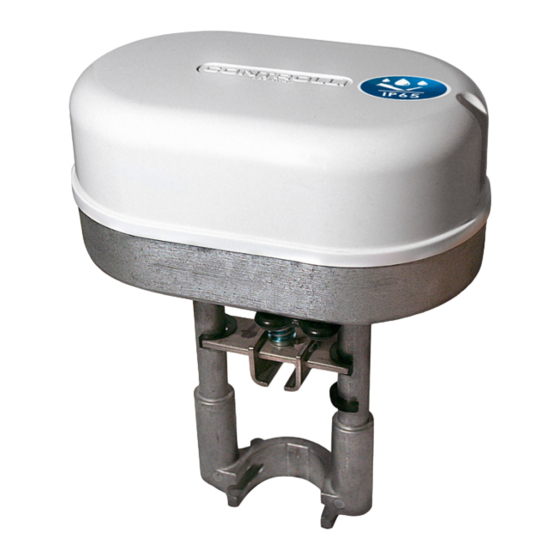
IP65 Globe Valves Actuators
FORCE
POWER
MODEL
[N]
SUPPLY
MVE504-65
400
MVE506-65
600
24Vac/dc
MVE510-65
1000
MVE515-65
1500
MVE504S-65
400
MVE506S-65
600
24Vac/dc
MVE510S-65
1000
MVE515S-65
1500
APPLICATION AND USE
MVE5xx-65 is a flexible electro mechanical actuator for the control
of two and three-way globe valves in:
•
heating and cooling systems;
•
Air Handling Units;
•
district heating plants;
•
industrial temperature control systems.
The actuator can be controlled either by a proportional (modulat-
ing) signal or by an increase/decrease (Floating) signal.
It is easy to mount and connect the actuator. Direct mounting is pos-
sible to any CONTROLLI flanged valve. Linkage kits are available for
CONTROLLI threaded valves as well as for valves of other manufac-
turers (table p. 3). The actuator has a fine resolution (500 steps on the
full stroke range) for exacting fluid control and it is able to self-cali-
brate on a different stroke without the need of any user action (this
function is DIP switch selectable on the field).
MVE5xx-65 has intelligent behaviour and alarm functionality in case
of unexpected operation, feedback of alarms to the user is provided
by LEDs (GREEN and RED) on the control board.
N.B.: Do not use the actuator if not coupled with its relating valve.
MVE5xx-65 is suitable for harsh environment requiring IP65 protection
degree.
OPERATION
The actuator translates the control signal (modulating or 3 point
floating) from the controller into a valve position. A modern brushless
DC motor in the actuator drive a gear train and a worm gear – screw
jack mechanism convert the motor revolutions into accurate and
repeatable linear movements.
Control Signal
MVE5xx-65 can be controlled by one of 2 main control types:
•
3 point floating ;
Controlli S.p.A.
16010 Sant'Olcese (GE)
Tel. 010 73 06 1
Fax. 010 73 06 870/871
www.controlli.eu
DESCRIPTION
long yoke, modulating/
floating control, IP65
short yoke, modulating/
floating control, IP65
1
Issue rev. b
st
•
Modulating (or proportional) signal with filed selectable
range (e.g., 0-10Vdc, 2-10Vdc, 0-5/2-6Vdc, 5-10/6-10Vdc and
4-20mA).
Manual Override
There is a manual operation handle on the actuator. When it is low-
ered (manual override ON), the power supply to the motor power
stage circuitry is cut and the motor stops. The actuator can be oper-
ated manually and the valve positioned accordingly.
The manual override lever stays in position until it is raised again, then
board and motor will be powered again. At the end of this operation
the actuator moves to initial position (on the basis of DIP n. 1 setting)
then it follows the control signal. When the manual override is en-
gaged the GREEN and the RED LED are ON.
Manual operation handle can also be used to modify any DIP switch
setting or as re-set function after any alarm occurrence.
The actuator is supplied with the manual override lowered (ON). It
is not necessary to remove power supply to modify DIP switches set-
ting.
Position Feedback
The actuator utilizes a 2-10Vdc position feedback (look at DIP n. 1
setting).
Calibration
The actuator has both auto and manual stroke calibration, DIP n. 7.
In factory delivery the auto stroke calibration is enabled – manual
calibration is not necessary unless maintenance is required on the
valve or certain alarm functions are desired.
End Point Auxiliary Switches (with accessory DMVE)
End point switches change over when the valve is fully open or
closed. They are free contacts with 24V AC/DC, 4A max voltage on
terminals. End point switches can be utilized to indicate valve stroke
end positions and for relay control of additional plant equipment.
When the actuators are controlled individually or in sequence, it is
possible to use the end switches to toggle when the valve is fully
open or fully closed. The auxiliary switch position according to con-
trol signal (Y) is shown in the picture below.
04/2018
DBL564e
MVE5xx-65
Page 1
Advertisement
Table of Contents

Related Manuals for Controlli MVE5-65 Series


Summary of Contents for Controlli MVE5-65 Series
- Page 1 It is easy to mount and connect the actuator. Direct mounting is pos- gaged the GREEN and the RED LED are ON. sible to any CONTROLLI flanged valve. Linkage kits are available for Manual operation handle can also be used to modify any DIP switch CONTROLLI threaded valves as well as for valves of other manufac- setting or as re-set function after any alarm occurrence.
-
Page 2: Technical Features
Diagnostic Relay Relay Control signal (Y) The actuator is provided with a self diagnostic algorithm able to de- tect faulty conditions: 0-0,5Vdc KC1 to K2 KC2 to K3 0,5-9,5Vdc KC1 to K1 KC2 to K3 • stroke calibration out of range 5-60mm; •... -
Page 3: Electric Connections
Properly VSXT09PBP, VSXT10PBP *** terminate the conduit in a suitable junction box. 2TGB.F/3TGB.F PN16 (not required) ASSEMBLING Controlli valves with threaded M40 connections AG51 (except for VSB/VMB/VSBF/ VMBF PN16) The actuator can be mounted with any orientation but never up-side down. - Page 4 PCB bending, do not press too much while fixing the terminal block. COMMAND + COMMAND - Matching between MVE terminal block and others Controlli actuators N.B.: M and Ln signals are internally connected. (*) MVE contain a single half-wave rectifier power supply. They must...
-
Page 5: Dip Switches Settings
DIP SWITCHES SETTINGS Set the DIP switches according to the tables here below. Power down and power up again the actuator or act on the manual over- ride to be sure that settings will be recognized. Factory settings switch Direct Action Reverse Action U = 2V U=10V... - Page 6 DIAGNOSTIC - ALARM FUNCTIONS Actuator behaviour LEDs Typical trouble Reset N° Error Actuator use behaviour shooting condition procedure Automatic calibration Manual calibration (DIP N. 7 OFF) (DIP N. 7 ON) The actuator pushes/pulls 2 The actuator pushes/pulls 2 times (unexpected stall) trying times against endpoint during to remove the possible obstacle.
-
Page 7: Dimensions (Mm)
STANDARD LEDs BEHAVIOUR N° LED behaviour Actuator status GREEN ON The actuator arrived at the extreme point of the stroke read GREEN BLINKING The actuator arrived at the intermediate point of the stroke read RED GREEN BLINKING The actuator is reading the stroke or it is going to initial position Manual control ON, the actuators ignores the control signal.
Need help?
Do you have a question about the MVE5-65 Series and is the answer not in the manual?
Questions and answers