
Subscribe to Our Youtube Channel
Related Manuals for Baumer Hubner HOG 9


Summary of Contents for Baumer Hubner HOG 9
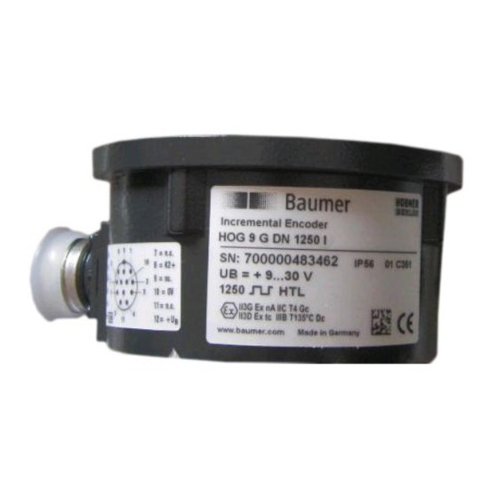
- Page 1 Montage- und Betriebsanleitung Mounting and operating instructions Option G Option EMS: LED Option EMS: LED HOG 9 (HOG 9 G) Inkrementaler Drehgeber (Zwillingsgeber) Incremental encoder (Twin encoder)
-
Page 2: Table Of Contents
Inhaltsverzeichnis Inhaltsverzeichnis Allgemeine Hinweise ..............................Betrieb in explosionsgefährdeten Bereichen ..................Sicherheitshinweise ..............................Vorbereitung .................................. Lieferumfang ..............................Zur Montage erforderlich (nicht im Lieferumfang enthalten) ........... Montage ..................................Schritt 1 ................................Schritt 2 ................................Schritt 3 - Einseitig offene Hohlwelle ....................Schritt 3 - Konuswelle .......................... - Page 3 Table of contents Table of contents General notes ................................Operation in potentially explosive environments ................. Security indications ..............................Preparation ..................................Scope of delivery ............................Required for mounting (not included in scope of delivery) ............Mounting ..................................Step 1 ................................Step 2 ................................
-
Page 4: Allgemeine Hinweise
Gebrauchte Elektro- und Elektronikgeräte dürfen nicht im Hausmüll entsorgt werden. Das Produkt enthält wertvolle Rohstoffe, die recycelt werden können. Wenn immer möglich sollen Altgeräte lokal am entsprechenden Sammeldepot entsorgt werden. Im Bedarfsfall gibt Baumer den Kunden die Möglichkeit, Baumer-Produkte fachgerecht zu entsor- gen. Weitere Informationen siehe www.baumer.com. Achtung! Beschädigung des auf dem Gerät befindlichen Siegels... -
Page 5: General Notes
Whenever possible, waste electrical and electronic equipment should be disposed locally at the authorized collection point. If necessary, Baumer gives customers the opportunity to dispose of Baumer products profession- ally. For further information see www.baumer.com. -
Page 6: Betrieb In Explosionsgefährdeten Bereichen
Betrieb in explosionsgefährdeten Bereichen Betrieb in explosionsgefährdeten Bereichen Das Gerät entspricht der Richtlinie 2014/34/EU für explosionsgefährdete Bereiche. Der Einsatz ist gemäß den Gerätekategorien 3 G (Ex-Atmosphäre Gas) und 3 D (Ex-Atmo- sphäre Staub) zulässig. Gerätekategorie 3 G: - Ex-Kennzeichnung: II 3 G Ex nA IIC T4 Gc - Normenkonformität: EN 60079-0:2012 + A11:2013 EN 60079-15:2010... -
Page 7: Operation In Potentially Explosive Environments
Operation in potentially explosive environments Operation in potentially explosive environments The device complies with the directive 2014/34/EU for potentionally explosive atmospheres. It can be used in accordance with equipment categories 3 G (explosive gas atmosphere) and 3 D (explosive dust atmosphere). Equipment category 3 G: - Ex labeling: II 3 G Ex nA IIC T4 Gc - Conforms to standard:... -
Page 8: Sicherheitshinweise
Sicherheitshinweise Sicherheitshinweise Verletzungsgefahr durch rotierende Wellen Haare und Kleidungsstücke können von rotierenden Wellen erfasst werden. • Vor allen Arbeiten alle Betriebsspannungen ausschalten und Maschinen stillsetzen. 3.2 Zerstörungsgefahr durch elektrostatische Aufladung Die elektronischen Bauteile im Gerät sind empfindlich gegen hohe Spannungen. • Steckkontakte und elektronische Komponenten nicht berühren. •... -
Page 9: Security Indications
Security indications Security indications Risk of injury due to rotating shafts Hair and clothes may become tangled in rotating shafts. • Before all work switch off all voltage supplies and ensure machinery is stationary. Risk of destruction due to electrostatic charge Electronic parts contained in the device are sensitive to high voltages. -
Page 10: Vorbereitung
Vorbereitung / Preparation Vorbereitung Preparation Lieferumfang Scope of delivery 1), 2) Gehäuse Housing Einseitig offene Hohlwelle oder Konuswelle Blind hollow shaft or cone shaft mit Schlüsselfläche SW 17 mm with spanner flat 17 mm a/f Spannelement Clamping element (nur bei einseitig offener Hohlwelle) (only for blind hollow shaft) Stütze für Drehmomentstütze Brace for torque arm Abdeckhaube mit O-Ring... -
Page 11: Zur Montage Erforderlich (Nicht Im Lieferumfang Enthalten)
Vorbereitung / Preparation Zur Montage erforderlich Required for mounting (nicht im Lieferumfang enthalten) (not included in scope of delivery) 15b 15c 3x 3x Drehmomentstütze, als Zubehör erhältlich: Torque arm, available as accessory: Bestellnummer Länge L, Version Order number Length L, version 11043628 67...70 mm, Standard 11043628... - Page 12 Vorbereitung / Preparation Zur Montage erforderlich Required for mounting (nicht im Lieferumfang enthalten) (not included in scope of delivery) Montage-/Demontageset als Zubehör Mounting/dismounting kit available as erhältlich: Bestellnummer accessory: Order number 11084868 (für Konuswelle) 11084868 (for cone shaft) 11081744 (für einseitig offene Hohlwelle) 11081744 (for blind hollow shaft) bestehend aus ...
-
Page 13: Montage
Montage / Mounting Montage Mounting In den Bildern am Beispiel vom HOG 9. Pictures showing the HOG 9 as example. Gleiche Montageschritte bei den anderen Same mounting steps for the other ver- Versionen. sions. Schritt 1 Step 1 10 mm 10 mm Schritt 2 Step 2... -
Page 14: Schritt 3 - Einseitig Offene Hohlwelle
Montage / Mounting Schritt 3 - Einseitig offene Hohlwelle Step 3 - Blind hollow shaft Zentrierbohrung Center hole DIN 332-D, M6x16 mm 52 mm (40...52 mm) 53 mm 52 mm (40-52 mm) ød ød1 12 mm ≥ ø15 mm 15 mm ≥ ø19 mm 16 mm ≥... -
Page 15: Schritt 3 - Konuswelle
Montage / Mounting Schritt 3 - Konuswelle Step 3 - Cone shaft Zentrierbohrung Center hole DIN 332-D, M6x16 mm 1:10 Antriebswelle einfetten. Lubricate drive shaft. Die Antriebswelle sollte einen The drive shaft should have as less möglichst kleinen Rundlauffehler runout as possible because this can aufweisen, da dieser zu einem otherwise result in an angle error, see Winkelfehler führen kann, siehe... -
Page 16: Schritt 4
Montage / Mounting Schritt 4 Step 4 1.6x8 mm 17 mm 5 mm 10 mm Anzugsmoment einseitig offene Hohlwelle: Tightening torque blind hollow shaft: = 6 Nm Anzugsmoment Konuswelle: Tightening torque cone shaft: = 3...4 Nm * Siehe Seite 7 oder 8 See page 7 or 8 MB004T1 - 11068581 Baumer_HOG9-HOG9G-T1_II_DE-EN (20A1) -
Page 17: Schritt 5 - Drehmomentstütze
Montage / Mounting Schritt 5 - Drehmomentstütze Step 5 - Torque arm Die Montage der Drehmomentstütze The torque arm should be mounted sollte spielfrei erfolgen. Ein Spiel von free from clearance. A play of just beispielsweise ±0,03 mm entspricht ±0.03 mm, results in a runout of the einem Rundlauffehler des Gerätes von device of 0.06 mm. -
Page 18: Hinweis Zur Vermeidung Von Messfehlern
Montage / Mounting Hinweis zur Vermeidung von Messfeh- How to prevent measurement errors lern Für einen einwandfreien Betrieb des To ensure that the device operates cor- Gerätes ist eine korrekte Montage, ins- rectly, it is necessary to mount it accu- besondere auch der Drehmomentstütze, rately as described in section 5.1 to 5.6, notwendig, wie beschrieben in Abschnitt... -
Page 19: Schritt 6
Montage / Mounting Schritt 6 Step 6 TX 10 * Siehe Seite 7 See page 7 MB004T1 - 11068581 Baumer_HOG9-HOG9G-T1_II_DE-EN (20A1) -
Page 20: Schritt 7 - Rundsteckverbinder (Zubehör)
Montage / Mounting Schritt 7 - Rundsteckverbinder (Zube- Step 7 - Mating connector (accessory) hör) Ansicht X Löteinsatz, Belegung siehe Abschnitt 7.3. ø7...12 mm View X Insert with solder contacts, Kabelschirm assignment see section 7.3. Cable shield Ansicht X View X EMV-Ring EMC ring Code... -
Page 21: Schritt 8 - Rundsteckverbinder (Zubehör)
Montage / Mounting 5.10 Schritt 8 - Rundsteckverbinder (Zube- 5.10 Step 8 - Mating connector (accessory) hör) Ansicht Y Siehe Abschnitt 7.3. View Y See section 7.3. Handfest Hand-tight * Siehe Seite 7 oder 8 See page 7 or 8 5.11 Montagehinweis 5.11... -
Page 22: Abmessungen
Abmessungen / Dimensions Abmessungen Dimensions Einseitig offene Hohlwelle Blind hollow shaft 6.1.1 Standard 6.1.1 Standard (73504, 73510, 73511, 73522, 73523, (73504, 73510, 73511, 73522, 73523, 73531, 73533, 73541, 73542) 73531, 73533, 73541, 73542) Positive Drehrichtung Positive rotating direction ød Zubehör Option Accessory 6.1.2... -
Page 23: Konuswelle
Abmessungen / Dimensions Konuswelle Cone shaft 6.2.1 Standard 6.2.1 Standard (73500, 73503, 73524, 73528, 73540) (73500, 73503, 73524, 73528, 73540) Positive Drehrichtung Positive rotating direction Zubehör Option Accessory 6.2.2 Option G: Zwillingsgeber HOG 9 G 6.2.2 Option G: Twin encoder HOG 9 G (73575, 73578) (73575, 73578) Positive Drehrichtung... -
Page 24: Elektrischer Anschluss
Elektrischer Anschluss / Electrical connection Elektrischer Anschluss Electrical connection Beschreibung der Anschlüsse 7.1 Terminal significance Betriebsspannung Voltage supply Masseanschluss (0V) Ground Erdungsanschluss (Gehäuse) Earth ground (housing) Ausgangssignal Kanal 1 Output signal channel 1 Ausgangssignal Kanal 1 invertiert Output signal channel 1 inverted Ausgangssignal Kanal 2 (90°... -
Page 25: Pinbelegung Flanschdose
Elektrischer Anschluss / Electrical connection Pinbelegung Flanschdose 7.3 Pin assignment flange connector 7.3.1 Standard 7.3.1 Standard Ansicht Y in Flanschdose, 12-polig, Stiftkontakte, rechtsdrehend, siehe Abschnitt 5.10. View Y into flange connector, 12-pin, male, CW, see section 5.10. 7.3.2 Option EMS 7.3.2 Option EMS (Enhanced Monitoring System) (Enhanced Monitoring System) 0V (@ Err) Ansicht Y... -
Page 26: Option Ems (Enhanced Monitoring System): Status Led / Fehlerausgang
Elektrischer Anschluss / Electrical connection Option EMS (Enhanced Monitoring Option EMS (Enhanced Monitoring System): Status LED / Fehlerausgang System): Status LED / Error output Rotblinkend Flash light red Signalfolge-, Nullimpuls- oder Impulszahl- Error of signal sequence, zero pulse or fehler pulses (Fehlerausgang = HIGH-LOW-Wechsel) (Error output = HIGH-LOW change) -
Page 27: Option Anschlusskabel: Belegung
Blau/Blue = 0V Sensorkabel HEK 8 (Zubehör) Sensor cable HEK 8 (accessory) Es wird empfohlen, das Baumer Hübner Baumer Hübner sensor cable HEK 8 is Sensorkabel HEK 8 zu verwenden oder recommended. As a substitute a shielded ersatzweise ein geschirmtes, paarig ver- twisted pair cable should be used. -
Page 28: Demontage
Demontage / Dismounting Demontage Dismounting In den Bildern am Beispiel vom HOG 9. Pictures showing the HOG 9 as example. Gleiche Demontageschritte bei den ande- Same dismounting steps for the other ren Versionen. versions. Vor der Demontage alle elektrischen Disconnect all electrical connections Verbindungen trennen. - Page 29 Demontage / Dismounting Schritt 3 Step 3 17 mm 5 mm Schritt 4 Step 4 0.8x4 mm * Siehe Seite 8 oder 9 See page 8 or 9 MB004T1 - 11068581 Baumer_HOG9-HOG9G-T1_II_DE-EN (20A1)
- Page 30 Demontage / Dismounting Schritt 5 Step 5 17 mm 6 mm Schritt 6 Step 6 * Siehe Seite 9 See page 9 MB004T1 - 11068581 Baumer_HOG9-HOG9G-T1_II_DE-EN (20A1)
-
Page 31: Zubehör
Zubehör / Accessories Zubehör Accessories • Drehmomentstütze Größe M6: • Torque arm size M6: Bestellnummer siehe Order number see Abschnitt 4.2. section 4.2. • Rundsteckverbinder M23: • Mating connector M23: Bestellnummer 11068577 Order number 11068577 • Sensorkabel für Drehgeber • Sensor cable for encoders HEK 8 HEK 8 •... -
Page 32: Technische Daten
Montage / Mounting Technische Daten Technische Daten 10.1 Technische Daten - elektrisch • Betriebsspannung: 9...30 VDC (HTL-P, TTL - Version R) 5 VDC ± 5 % (TTL) • Betriebsstrom ohne Last: ≤100 mA • Impulse pro Umdrehung: 300...5000 (je nach Bestellung) •... -
Page 33: Technical Data
Technical data Technical data 10.1 Technical data - electrical ratings • Voltage supply: 9...30 VDC (HTL-P, TTL - version R) 5 VDC ± 5 % (TTL) • Consumption w/o load: ≤100 mA • Pulses per revolution: 300...5000 (as ordered) • Phase shift: 90° ±20° •... -
Page 34: Eu-Konformitätserklärung
Signature/nom/fonction Baumer_HOGx_OGx_POGx_FOGx_HMI_DE-EN-FR_CoC_81201236.docm/kwe Baumer Hübner GmbH P.O. Box 126943 ∙ D-10609 Berlin ∙ Max-Dohrn-Str. 2+4 ∙ D-10589 Berlin Phone +49 (0)30 69003-0 ∙ Fax +49 (0)30 69003-104 ∙ info@baumerhuebner.com ∙ www.baumer.com Sitz der Gesellschaft / Registered Office: Berlin, Germany ∙ Geschäftsführer / Managing Director: Dr. Oliver Vietze, Dr. Johann Pohany Handelsregister / Commercial Registry: AG Charlottenburg HRB 96409 ∙... - Page 35 MB004T1 - 11068581 Baumer_HOG9-HOG9G-T1_II_DE-EN (20A1)
- Page 36 Baumer Hübner GmbH P.O. Box 12 69 43 · 10609 Berlin, Germany Phone: +49 (0)30/69003-0 · Fax: +49 (0)30/69003-104 info@baumerhuebner.com · www.baumer.com/motion Version: 73500, 73503, 73504, (73508), 73510, 73511, 73522, 73523, 73524, 73528, 73531, 73533, 73575, 73577, 73578, 73579, 73540,...
Need help?
Do you have a question about the Hubner HOG 9 and is the answer not in the manual?
Questions and answers