
Related Manuals for Baumer HOG 16


Summary of Contents for Baumer HOG 16
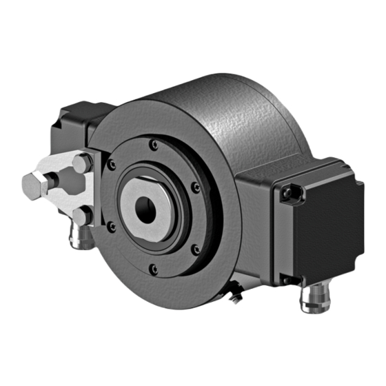
- Page 1 Montage- und Betriebsanleitung Mounting and operating instructions Option M: redundant HOG 16 Inkrementaler Drehgeber mit Spannelement und Gewindebuchse Incremental encoder with clamping element and insert nut...
-
Page 2: Table Of Contents
Schritt 11 - Klemmenkasten ........................4.12 Schritt 12 - Klemmenkasten ........................4.13 Montagehinweis ............................Abmessungen ................................Einfache Abtastung ............................ Option M: Redundante Abtastung HOG 16 M ................Elektrischer Anschluss ............................Beschreibung der Anschlüsse ......................Sensorkabel HEK 8 (Zubehör) ......................Klemmenbelegung ............................Ausgangssignale ............................ - Page 3 ..........................4.12 Step 12 - Terminal box ..........................4.13 Mounting instruction ..........................Dimensions .................................. Single sensing ............................... Option M: Redundant sensing HOG 16 M ..................Electrical connection ............................6.1 Terminal significance ..........................Sensor cable HEK 8 (accessory) ......................Terminal assignment ..........................
-
Page 4: Allgemeine Hinweise
Information Empfehlung für die Gerätehandhabung Der inkrementale Drehgeber HOG 16 ist ein opto-elektronisches Prä zi sionsmessgerät, das mit Sorgfalt nur von technisch qualifiziertem Per sonal gehandhabt werden darf. Die zu erwartende Lebensdauer des Gerätes hängt von den Kugellagern ab, die mit einer Dauerschmierung ausgestattet sind. -
Page 5: General Notes
Information Recommendation for device handling The incremental encoder HOG 16 is an opto electro nic precision measurement device which must be handled with care by skilled personnel only. The expected service life of the device depends on the ball bearings, which are equipped with a permanent lubrication. -
Page 6: Sicherheitshinweise
Sicherheitshinweise Sicherheitshinweise Verletzungsgefahr durch rotierende Wellen Haare und Kleidungsstücke können von rotierenden Wellen erfasst werden. • Vor allen Arbeiten alle Betriebsspannungen ausschalten und Maschinen stillsetzen. Zerstörungsgefahr durch elektrostatische Aufladung Die elektronischen Bauteile im Gerät sind empfindlich gegen hohe Spannungen. • Steckkontakte und elektronische Komponenten nicht berühren. •... -
Page 7: Security Indications
Security indications Security indications Risk of injury due to rotating shafts Hair and clothes may become tangled in rotating shafts. • Before all work switch off all voltage supplies and ensure machinery is stationary. Risk of destruction due to electrostatic charge Electronic parts contained in the device are sensitive to high voltages. -
Page 8: Vorbereitung
Vorbereitung / Preparation Vorbereitung Preparation Lieferumfang Gerät Scope of delivery of the device Gehäuse Housing Durchgehende Hohlwelle ø20...38 mm Through hollow shaft ø20...38 mm mit Schlüsselfläche SW 45 mm with spanner flat 45 mm a/f Gewindebuchse ø20...38 mm Insert nut ø20...38 mm mit Schlüsselfläche SW 36 mm (ø20...25 mm) with spanner flat 36 mm a/f (ø20...25 mm) oder SW 46 mm (ø28...38 mm) or spanner flat 46 mm a/f (ø28...38 mm) -
Page 9: Lieferumfang Klemmenkasten
Abschnitt 4.10 und 6.3. see section 4.10 and 6.3. Torx-/Schlitzschraube M3x10 mm Torx/slotted screw M3x10 mm D-SUB Stecker am D-SUB connector (male) on the Gerätegehäuse device housing Option M: Redundante Abtastung HOG 16 Option M: Redundant sensing HOG 16 MB098T1 - 11055709 Baumer_HOG16-HOG16M-T1_II_DE-EN (20A2) -
Page 10: Zur Montage Erforderlich (Nicht Im Lieferumfang Enthalten)
Vorbereitung / Preparation Zur Montage erforderlich Required for mounting (nicht im Lieferumfang enthalten) (not included in scope of delivery) 3x 3x Drehmomentstütze, als Zubehör erhältlich: Torque arm, available as accessory: Bestellnummer Länge L, Version Order number Length L, version 11043628 67...70 mm, Standard 11043628 67...70 mm, standard 11004078... -
Page 11: Erforderliches Werkzeug (Nicht Im Lieferumfang Enthalten)
Vorbereitung / Preparation Erforderliches Werkzeug Required tools (nicht im Lieferumfang enthalten) (not included in scope of delivery) 1,6x8,0 mm 1.6x8.0 mm 10 (2x), 36 oder 46 mm 10 (2x), 36 or 46 mm und 45 mm and 45 mm TX 10, TX 20 TX 10, TX 20 Werkzeugset als Zubehör erhältlich: Tool kit available as accessory:... -
Page 12: Montage
Montage / Mounting Montage Mounting In den Bildern am Beispiel des Typs Pictures showing type HOG 16 as exam- HOG 16. Gleiche Montageschritte bei ple. Same mounting steps for redundant redundanter Version HOG 16 M. version HOG 16 M. Schritt 1... -
Page 13: Schritt 3
Montage / Mounting Schritt 3 Step 3 10 mm * Siehe Seite 7 See page 7 Antriebswelle einfetten. Lubricate drive shaft. Die Antriebswelle sollte einen The drive shaft should have as less möglichst kleinen Rundlauffehler runout as possible because this can aufweisen, da dieser zu einem otherwise result in an angle error, see Winkelfehler führen kann, siehe... -
Page 14: Schritt 4 - Drehmomentstütze
Montage / Mounting Schritt 4 - Drehmomentstütze Step 4 - Torque arm Die Montage der Drehmomentstütze The torque arm should be mounted sollte spielfrei erfolgen. Ein Spiel von free from clearance. A play of just beispielsweise ±0,03 mm entspricht ±0.03 mm, results in a runout of the einem Rundlauffehler des Gerätes von device of 0.06 mm. -
Page 15: Hinweis Zur Vermeidung Von Messfehlern
Montage / Mounting Hinweis zur Vermeidung von Messfeh- How to prevent measurement errors lern Für einen einwandfreien Betrieb des To ensure that the device operates cor- Gerätes ist eine korrekte Montage, ins- rectly, it is necessary to mount it accu- besondere auch der Drehmomentstütze, rately as described in section 4.1 to 4.4, notwendig, wie beschrieben in Abschnitt... -
Page 16: Schritt 5
Montage / Mounting Schritt 5 Step 5 45 mm 36 mm (ø20...25 mm) 46 mm (ø28...38 mm) Anzugsmoment: Tightening torque: = 3 Nm 1.6x8 mm Schritt 6 Step 6 TX 20 Anzugsmoment: Tightening torque: = 3 Nm * Siehe Seite 5 oder 7 See page 5 or 7 MB098T1 - 11055709 Baumer_HOG16-HOG16M-T1_II_DE-EN (20A2) -
Page 17: Schritt 7 - Klemmenkasten
Montage / Mounting 4.7.1 Schritt 6 - Option 4.7.1 Step 6 - Option Anzugsmoment: Tightening torque: = 3 Nm TX 20 Schritt 7 - Klemmenkasten Step 7 - Terminal box TX 20 22 mm * Siehe Seite 5 oder 6 See page 5 or 6 MB098T1 - 11055709 Baumer_HOG16-HOG16M-T1_II_DE-EN (20A2) -
Page 18: Schritt 8 - Klemmenkasten
Montage / Mounting Schritt 8 - Klemmenkasten Step 8 - Terminal box TX 10 4.10 Schritt 9 und 10 - Klemmenkasten 4.10 Step 9 and 10 - Terminal box Ansicht X siehe Abschnitt 6.3. Kabelschirm 13c * View X Cable shield see section 6.3. -
Page 19: Schritt 11 - Klemmenkasten
Montage / Mounting 4.11 Schritt 11 - Klemmenkasten 4.11 Step 11 - Terminal box D-SUB Buchse zum Anschluss an Gerätegehäuse TX 10 siehe Abschnitt 4.12. D-SUB connector (female) for connecting to device housing see section 4.12. 13c * 22 mm 4.12 Schritt 12 - Klemmenkasten 4.12... -
Page 20: Montagehinweis
Montage / Mounting 4.13 Montagehinweis 4.13 Mounting instruction Wir empfehlen, das Gerät so zu It is recommended to mount the device montieren, dass der Kabelanschluss with cable connection facing down- keinem direkten Wassereintritt ward and being not exposed to water. ausgesetzt ist. -
Page 21: Abmessungen
Abmessungen / Dimensions Abmessungen Dimensions Einfache Abtastung Single sensing (74101, 74168, 74254, 74256, 74273) (74101, 74168, 74254, 74256, 74273) Um 90° versetzt gezeichnet Drawing 90° rotated 96.5 Option Positive Drehrichtung Zubehör Positive rotating direction Accessory ød1 ød2 M 32 M 32 M 32 M 45 M 45 M 45... -
Page 22: Option M: Redundante Abtastung Hog 16 M
Abmessungen / Dimensions Option M: Redundante Abtastung Option M: Redundant sensing HOG 16 M HOG 16 M (74093, 74108) (74093, 74108) Um 90° versetzt gezeichnet Drawing 90° rotated 96.5 Option Positive Drehrichtung Zubehör Positive rotating direction Accessory ød1 ød2 M 32 M 32... -
Page 23: Elektrischer Anschluss
Do not use Sensorkabel HEK 8 (Zubehör) Sensor cable HEK 8 (accessory) Es wird empfohlen, das Baumer Hübner Baumer Hübner sensor cable HEK 8 is Sensorkabel HEK 8 zu verwenden oder recommended. As a substitute a shielded ersatzweise ein geschirmtes, paarig ver- twisted pair cable should be used. -
Page 24: Klemmenbelegung
Elektrischer Anschluss / Electrical connection Klemmenbelegung Terminal assignment 6.3.1 D … I, D ... TTL 6.3.1 D … I, D ... TTL Max. 1,5 mm Ansicht X Max. AWG 16 Anschlussklemmen, siehe Abschnitt 4.10. View X Connecting terminal, see section 4.10. 0V ( ) Zwischen besteht keine Verbindung. -
Page 25: Betrieb Und Wartung
Betrieb und Wartung / Operation and maintenance Betrieb und Wartung Operation and maintenance Austausch der Kohlebürste Replace of the carbon brush Bei Erreichen der minimalen Kohle- When the minimum cabon brush length bürstenlänge (L) von 5,3 mm sollte die (L) of 5.3 mm is reached, the carbon Kohlebürste ausgewechselt werden, brush should be replaced in order to damit weiterhin ein einwandfreier Betrieb... -
Page 26: Demontage
Demontage / Dismounting Demontage Dismounting In den Bildern am Beispiel des Typs Pictures showing type HOG 16 as exam- HOG 16. Gleiche Demontageschritte bei ple. Same dismounting steps for redun- redundanter Version HOG 16 M. dant version HOG 16 M. Schritt 1 und 2 Step 1 and 2 Elektrische Verbindung trennen. -
Page 27: Schritt 3
Demontage / Dismounting Schritt 3 Step 3 TX 20 10 mm 1.6x8 mm Schritt 4 Step 4 45 mm 36 mm (ø20...25 mm) 46 mm (ø28...38 mm) * Siehe Seite 5 oder 7 See page 5 or 7 MB098T1 - 11055709 Baumer_HOG16-HOG16M-T1_II_DE-EN (20A2) -
Page 28: Step 5
Demontage / Dismounting Schritt 5 Step 5 MB098T1 - 11055709 Baumer_HOG16-HOG16M-T1_II_DE-EN (20A2) -
Page 29: Zubehör
Zubehör / Accessories Zubehör Accessories • Drehmomentstütze Größe M6: • Torque arm size M6: Bestellnummer siehe Order number see Abschnitt 3.3. section 3.3. • Montageset für Drehmoment- • Mounting kit for torque arm stütze Größe M6 und Erdungs- size M6 and earthing strap: band: Bestellnummer 11077197 Order number 11077197 •... -
Page 30: Technische Daten
Technische Daten Technische Daten 10.1 Technische Daten - elektrisch • Betriebsspannung: 9...30 VDC (HTL) 9...26 VDC (TTL - Version R) 5 VDC ±5 % (TTL) • Betriebsstrom ohne Last: ≤100 mA • Impulse pro Umdrehung: 250...2500 (je nach Bestellung) • Phasenverschiebung: 90°... -
Page 31: Technical Data
Technical data Technical data 10.1 Technical data - electrical ratings • Voltage supply: 9...30 VDC (HTL) 9...26 VDC (TTL - version R) 5 VDC ±5 % (TTL) • Consumption w/o load: ≤100 mA • Pulses per revolution: 250...2500 (as ordered) • Phase shift: 90°... - Page 32 Baumer Hübner GmbH P.O. Box 12 69 43 · 10609 Berlin, Germany Phone: +49 (0)30/69003-0 · Fax: +49 (0)30/69003-104 info@baumerhuebner.com · www.baumer.com/motion Version: 74093, 74101, 74108, 74168, 74254, 74256, 74273 MB098T1 - 11055709 Baumer_HOG16-HOG16M-T1_II_DE-EN (20A2-13.03.2020)
Need help?
Do you have a question about the HOG 16 and is the answer not in the manual?
Questions and answers