
Related Manuals for Baumer Hubner Berlin HOGS 100


Summary of Contents for Baumer Hubner Berlin HOGS 100
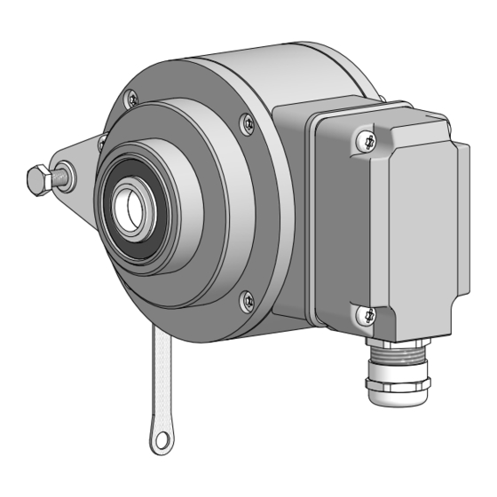
- Page 1 Montage- und Betriebsanleitung Mounting and operating instructions Option Heizung Option heating HOGS 100 Sinus Drehgeber mit radialem Klemmenkasten Sine encoder with radial terminal box...
-
Page 2: Table Of Contents
Inhaltsverzeichnis Inhaltsverzeichnis Allgemeine Hinweise ................................Betrieb in explosionsgefährdeten Bereichen (nur bei option ATEX) ........... Sicherheitshinweise ................................Vorbereitung .................................... Lieferumfang Gerät ......................7 Lieferumfang Klemmenkasten .................... 8 Zur Montage erforderlich (nicht im Lieferumfang enthalten) ..................9 Zur Demontage erforderlich (nicht im Lieferumfang enthalten) ..................10 Erforderliches Werkzeug (nicht im Lieferumfang enthalten) .................. - Page 3 Table of contents Table of contents General notes ..................................Operation in potentially explosive environments (only with option ATEX) ........Security indications ................................Preparation ....................................Scope of delivery of the device ......................... Scope of delivery terminal box .......................... Required for mounting (not included in scope of delivery) ........................
-
Page 4: Allgemeine Hinweise
Gebrauchte Elektro- und Elektronikgeräte dürfen nicht im Hausmüll entsorgt werden. Das Produkt enthält wertvolle Rohstoffe, die recycelt werden können. Wenn immer möglich sollen Altgeräte lokal am entsprechenden Sammeldepot entsorgt werden. Im Bedarfsfall gibt Baumer den Kunden die Möglichkeit, Baumer-Produkte fachgerecht zu entsor- gen. Weitere Informationen siehe www.baumer.com. Achtung! Beschädigung des auf dem Gerät befindlichen Siegels... -
Page 5: General Notes
Whenever possible, waste electrical and electronic equipment should be disposed locally at the authorized collection point. If necessary, Baumer gives customers the opportunity to dispose of Baumer products profession- ally. For further information see www.baumer.com. -
Page 6: Betrieb In Explosionsgefährdeten Bereichen (Nur Bei Option Atex)
Betrieb in explosionsgefährdeten Bereichen Betrieb in explosionsgefährdeten Bereichen (nur bei Option ATEX) Das Gerät entspricht der Richtlinie 2014/34/EU für explosionsgefährdete Bereiche. Der Einsatz ist gemäß den Gerätekategorien 3 G (Ex-Atmosphäre Gas) und 3 D (Ex-Atmo- sphäre Staub) zulässig. Ausnahme: Versionen mit Heizung dürfen nicht in explosionsge- fährdeten Bereichen eingesetzt werden. -
Page 7: Operation In Potentially Explosive Environments (Only With Option Atex)
Operation in potentially explosive environments Operation in potentially explosive environments (only with option ATEX) The device complies with the directive 2014/34/EU for potentionally explosive atmospheres. It can be used in accordance with equipment categories 3 G (explosive gas atmosphere) and 3 D (explosive dust atmosphere). -
Page 8: Sicherheitshinweise
Sicherheitshinweise Sicherheitshinweise Verletzungsgefahr durch rotierende Wellen Haare und Kleidungsstücke können von rotierenden Wellen erfasst werden. • Vor allen Arbeiten alle Betriebsspannungen ausschalten und Maschinen stillsetzen. Zerstörungsgefahr durch elektrostatische Aufladung Die elektronischen Bauteile im Gerät sind empfindlich gegen hohe Spannungen. • Steckkontakte und elektronische Komponenten nicht berühren. •... -
Page 9: Security Indications
Security indications Security indications Risk of injury due to rotating shafts Hair and clothes may become tangled in rotating shafts. • Before all work switch off all voltage supplies and ensure machinery is stationary. Risk of destruction due to electrostatic charge Electronic parts contained in the device are sensitive to high voltages. -
Page 10: Vorbereitung
Vorbereitung / Preparation Vorbereitung Preparation Lieferumfang Gerät Scope of delivery of the device Gehäuse Housing Einseitig offene Hohlwelle oder Konuswelle Blind hollow shaft or cone shaft with spanner mit Schlüsselfläche SW 17 mm flat 17 mm a/f Spannelement Clamping element (nur bei einseitig offener Hohlwelle) (only for blind hollow shaft) NORD-LOCK Scheibe NL6 SP SS NORD-LOCK washer NL6 SP SS... -
Page 11: Lieferumfang Klemmenkasten
Vorbereitung / Preparation Lieferumfang Klemmenkasten Scope of delivery terminal box Klemmenkastendeckel Terminal box cover Torx-/Schlitzschraube M4x32 mm Torx/slotted screw M4x32 mm Kabelverschraubung M20x1,5 mm Cable gland M20x1.5 mm für Kabel ø5...13 mm for cable ø5...13 mm Anschlussplatine, Connecting board, siehe Abschnitt 5.12 und 7.2. see section 5.12 and 7.2. Torx-/Schlitzschraube M3x10 mm Torx/slotted screw M3x10 mm D-SUB Stecker... -
Page 12: Zur Montage Erforderlich (Nicht Im Lieferumfang Enthalten)
Vorbereitung / Preparation Zur Montage erforderlich Required for mounting (nicht im Lieferumfang enthalten) (not included in scope of delivery) 17b 17c 3x 3x Drehmomentstütze, als Zubehör erhältlich: Torque arm, available as accessory: Bestellnummer Länge L, Version Order number Length L, version 11043628 67...70 mm, Standard 11043628 67...70 mm, standard... -
Page 13: Zur Demontage Erforderlich (Nicht Im Lieferumfang Enthalten)
Vorbereitung / Preparation Zur Demontage erforderlich Required for dismounting (nicht im Lieferumfang enthalten) (not included in scope of delivery) Demontageset als Zubehör erhältlich: Dismounting kit available as accessory: Bestellnummer 11077087: Order number 11077087: Gewindestift M6x10 mm, ISO 7436 Setscrew M6x10 mm, ISO 7436 Abdrückschraube M8x45 mm, ISO 4762 Jack screw M8x45 mm, ISO 4762 Erforderliches Werkzeug... -
Page 14: Montage
Montage / Mounting Montage Mounting Schritt 1 Step 1 10 mm 10 mm Schritt 2 Step 2 3 mm * Siehe Seite 7 oder 9 See page 7 or 9 MB183T1 - 11079092 Baumer_HOGS100_T1_DE_EN_202104_MI_11079092 (21A1) -
Page 15: Schritt 3 - Einseitig Offene Hohlwelle
Montage / Mounting Schritt 3 - Einseitig offene Hohlwelle Step 3 - Blind hollow shaft Zentrierbohrung Center hole DIN 332-D, M6x16 mm 53 mm (35 mm bei/at ød = 20 mm) ød ød1 12 mm ≥ ø15 mm 52 mm (40...52 mm) 16 mm ≥... -
Page 16: Schritt 3 - Konuswelle
Montage / Mounting Schritt 3 - Konuswelle Step 3 - Cone shaft Zentrierbohrung Center hole DIN 332-D, M6x16 mm 1:10 Antriebswelle einfetten. Lubricate drive shaft. Die Antriebswelle sollte einen The drive shaft should have as less möglichst kleinen Rundlauffehler runout as possible because this can aufweisen, da dieser zu einem otherwise result in an angle error, see Winkelfehler führen kann, siehe... -
Page 17: Schritt 4
Montage / Mounting Schritt 4 Step 4 Zul. Anzugsmoment einseitig offene Hohlwelle: Max. tightening torque blind hollow shaft: = 6 Nm Zul. Anzugsmoment Konuswelle: Max. tightening torque cone shaft: 17 mm = 3...4 Nm 5 mm 10 mm 1.6x8 mm * Siehe Seite 7 oder 9 See page 7 or 9 MB183T1 - 11079092... -
Page 18: Schritt 5 - Drehmomentstütze
Montage / Mounting Schritt 5 - Drehmomentstütze Step 5 - Torque arm Die Montage der Drehmomentstütze The torque arm should be mounted sollte spielfrei erfolgen. Ein Spiel von free from clearance. A play of just beispielsweise ±0,03 mm entspricht ±0.03 mm, results in a runout of the einem Rundlauffehler des Gerätes von device of 0.06 mm. -
Page 19: Hinweis Zur Vermeidung Von Messfehlern
Montage / Mounting Hinweis zur Vermeidung von Messfeh- How to prevent measurement errors lern Für einen einwandfreien Betrieb des To ensure that the device operates cor- Gerätes ist eine korrekte Montage, ins- rectly, it is necessary to mount it accu- besondere auch der Drehmomentstütze, rately as described in section 5.1 to 5.6, notwendig, wie beschrieben in Abschnitt... -
Page 20: Schritt 6
Montage / Mounting Schritt 6 Step 6 3 mm Zul. Anzugsmoment Max. tightening torque = 2...3 Nm * Siehe Seite 7 See page 7 Montagehinweis Mounting instruction Wir empfehlen, das Gerät so zu It is recommended to mount the device montieren, dass der Kabelanschluss with cable connection facing down- keinem direkten Wassereintritt... -
Page 21: Schritt 7
Montage / Mounting 5.10 Schritt 7 5.10 Step 7 TX 20 13c * 22 mm 5.11 Schritt 8 und 9 - Klemmenkasten 5.11 Step 8 and 9 - Terminal box TX 10 ø5...13 mm * Siehe Seite 8 oder 9 See page 8 or 9 Zur Gewährleistung der angegebenen To ensure the specified protection of... -
Page 22: Schritt 10 - Klemmenkasten
Montage / Mounting 5.12 Schritt 10 - Klemmenkasten 5.12 Step 10 - Terminal box Ansicht X siehe Abschnitt 7.2. View X Kabelschirm see section 7.2. Cable shield 5.13 Schritt 11 - Klemmenkasten 5.13 Step 11 - Terminal box D-SUB Buchse 13e * zum Anschluss an Gerätegehäuse... -
Page 23: Schritt 12 - Klemmenkasten
Montage / Mounting 5.14 Schritt 12 - Klemmenkasten 5.14 Step 12 - Terminal box Zul. Anzugsmoment Max. tightening torque = 2...3 Nm TX 20 TX 20 Großer, um 180° Zul. Anzugsmoment wendbarer Klemmenkasten Max. tightening torque Big terminal box, = 2...3 Nm turn by 180°... -
Page 24: Abmessungen
Abmessungen / Dimensions Abmessungen Dimensions Einseitig offene Hohlwelle Blind hollow shaft (74156, 74159) (74156, 74159) Positive Drehrichtung Positive rotating direction Um 90° versetzt gezeichnet Drawing 90° rotated ød 65.5 65.5 Zubehör Accessory Konuswelle Cone shaft (74247) (74247) Positive Drehrichtung Positive rotating direction Um 90°... -
Page 25: Einseitig Offene Hohlwelle Und Option Heizung
Abmessung / Dimension Einseitig offene Hohlwelle und Option Blind hollow shaft and option heating Heizung (74244) (74244) Um 90° versetzt gezeichnet Positive Drehrichtung Drawing 90° rotated Positive rotating direction Zubehör Accessory ød 65.5 65.5 Stromanschluss, siehe Abschnitt 7.3. Power supply, see section 7.3. Alle Abmessungen in Millimeter (wenn nicht anders angegeben) All dimensions in millimeters (unless otherwise stated) MB183T1 - 11079092... -
Page 26: Elektrischer Anschluss
Elektrischer Anschluss / Electrical connection Elektrischer Anschluss Electrical connection Beschreibung der Anschlüsse Terminal significance Betriebsspannung +UB; + Voltage supply Masseanschluss ; ; GND; 0V Ground Erdungsanschluss (Gehäuse) Earth ground (housing) Ausgangssignal Kanal 1 K1; A; A+ Output signal channel 1 Ausgangssignal Kanal 1 invertiert K1;... -
Page 27: Ausgangssignale
Sequence for positive rotating direction, see section 6. Sensorkabel HEK 8 (Zubehör) Sensor cable HEK 8 (accessory) Es wird empfohlen, das Baumer Hübner Baumer Hübner sensor cable HEK 8 is Sensorkabel HEK 8 zu verwenden oder recommended. As a substitute a shielded ersatzweise ein geschirmtes, paarig ver- twisted pair cable should be used. -
Page 28: Demontage
Demontage / Dismounting Demontage Dismounting Schritt 1 und 2 Step 1 and 2 TX 10 TX 20 13e * 22 mm 13c * * Siehe Seite 8 oder 9 See page 8 or 9 MB183T1 - 11079092 Baumer_HOGS100_T1_DE_EN_202104_MI_11079092 (21A1) - Page 29 Demontage / Dismounting Schritt 3 Step 3 1.6x8 mm 10 mm Schritt 4 Step 4 11 * 10 * 3 mm Schritt 5 Step 5 17 mm 5 mm * Siehe Seite 7 oder 9 See page 7 or 9 MB183T1 - 11079092 Baumer_HOGS100_T1_DE_EN_202104_MI_11079092 (21A1)
- Page 30 Demontage / Dismounting Schritt 6 Step 6 0.8x4 mm Schritt 7 Step 7 17 mm 6 mm Schritt 8 Step 8 * Siehe Seite 9 See page 9 MB183T1 - 11079092 Baumer_HOGS100_T1_DE_EN_202104_MI_11079092 (21A1)
-
Page 31: Zubehör
Zubehör / Accessories Zubehör Accessories • Drehmomentstütze Größe M6: • Torque arm size M6: Bestellnummer siehe Order number see Abschnitt 4.3. section 4.3. • Sensorkabel für Drehgeber • Sensor cable for encoders HEK 8 HEK 8 • Montageset für Drehmoment- • Mounting kit for torque arm stütze Größe M6 und Erdungsband: size M6 and earthing strap: Bestellnummer 11077197... -
Page 32: Technische Daten
Montage / Mounting Technische Daten Technische Daten 10.1 Technische Daten - elektrisch • Betriebsspannung: 5 VDC ±10 % (Version DN ...) 9...30 VDC (Version DN ... R) • Betriebsstrom ohne Last: ≤90 mA • Sinusperioden pro Umdrehung: 720...5000 (je nach Bestellung) •... -
Page 33: Technical Data
Technical data Technical data 10.1 Technical data - electrical ratings • Voltage supply: 5 VDC ±10 % (version DN ...) 9...30 VDC (version DN ... R) • Consumption w/o load: ≤90 mA • Sinewave cycles per turn: 720...5000 (as ordered) • Phase shift: 90°... -
Page 34: Eu-Konformitätserklärung
Signature/nom/fonction Baumer_HOGSx_OGSx_AMGx_HMGx_DE-EN-FR_CoC_81201176.docm/kwe Baumer Hübner GmbH P.O. Box 126943 ∙ D-10609 Berlin ∙ Max-Dohrn-Str. 2+4 ∙ D-10589 Berlin Phone +49 (0)30 69003-0 ∙ Fax +49 (0)30 69003-104 ∙ info@baumerhuebner.com ∙ www.baumer.com Sitz der Gesellschaft / Registered Office: Berlin, Germany ∙ Geschäftsführer / Managing Director: Dr. Oliver Vietze, Dr. Johann Pohany Handelsregister / Commercial Registry: AG Charlottenburg HRB 96409 ∙... - Page 35 MB183T1 - 11079092 Baumer_HOGS100_T1_DE_EN_202104_MI_11079092 (21A1)
- Page 36 Baumer Hübner GmbH P.O. Box 12 69 43 · 10609 Berlin, Germany Phone: +49 (0)30/69003-0 · Fax: +49 (0)30/69003-104 info@baumerhuebner.com · www.baumer.com/motion Version: 74156, 74159, 74244 MB183T1 - 11079092 Baumer_HOGS100_T1_DE_EN_202104_MI_11079092 (21A1-19.04.2021)
Need help?
Do you have a question about the Hubner Berlin HOGS 100 and is the answer not in the manual?
Questions and answers