
Subscribe to Our Youtube Channel
Related Manuals for Baumer HUBNER BERLIN HOG 10 - Niro


Summary of Contents for Baumer HUBNER BERLIN HOG 10 - Niro
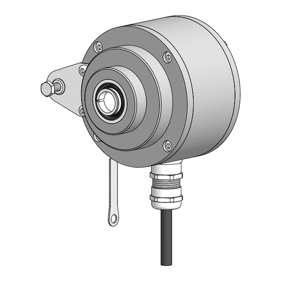
- Page 1 Montage- und Betriebsanleitung Installation and operating instructions HOG 10 - Niro Inkrementaler Drehgeber Version mit Sensorkabel HEK 8 Incremental Encoder Version with sensor cable HEK 8...
-
Page 2: Table Of Contents
Inhaltsverzeichnis Inhaltsverzeichnis Allgemeine Hinweise ..............................Betrieb in explosionsgefährdeten Bereichen ..................... Sicherheitshinweise ..............................Vorbereitung ..................................Lieferumfang ................................ Zur Montage erforderlich (nicht im Lieferumfang enthalten) ............Zur Demontage erforderlich (nicht im Lieferumfang enthalten) ..........Erforderliches Werkzeug (nicht im Lieferumfang enthalten) ............Montage .................................... - Page 3 Table of contents Table of contents General notes ................................... Operation in potentially explosive environments ..................Security indications ..............................Preparation ..................................Scope of delivery ............................... Required for mounting (not included in scope of delivery) ............Required for dismounting (not included in scope of delivery) ............
-
Page 4: Allgemeine Hinweise
Allgemeine Hinweise Allgemeine Hinweise Zeichenerklärung: Gefahr Warnung bei möglichen Gefahren Hinweis zur Beachtung Hinweis zur Gewährleistung eines einwandfreien Betriebes des Produkts Information Empfehlung für die Produkthandhabung Der inkrementale Drehgeber HOG 10 ist ein opto-elektronisches Prä zi sionsmessgerät, das mit Sorgfalt nur von technisch qualifiziertem Per sonal gehandhabt werden darf. -
Page 5: General Notes
General notes General notes Symbol guide: Danger Warnings of possible danger General information for attention Informations to ensure correct product operation Information Recommendation for product handling The incremental encoder HOG 10 is an opto electro nic precision measurement device which must be handled with care by skilled personnel only. -
Page 6: Betrieb In Explosionsgefährdeten Bereichen
Betrieb in explosionsgefährdeten Bereichen Betrieb in explosionsgefährdeten Bereichen Das Gerät entspricht der Norm EG-Richtlinie 2014/34/EU für explosionsgefährdete Bereiche. Der Einsatz ist gemäß den Gerätekategorien 3 G (Ex-Atmosphäre Gas) und 3 D (Ex-Atmosphäre Staub) zulässig. Gerätekategorie 3 G: - Ex-Kennzeichnung: II 3 G Ex nA IIC T4 Gc - Normenkonformität: EN 60079-0:2012 + A11:2013 EN 60079-15:2010... -
Page 7: Operation In Potentially Explosive Environments
Operation in potentially explosive environments Operation in potentially explosive environments The device complies with the EU standard 2014/34/EU for potentionally explosive atmospheres. It can be used in accordance with equipment categories 3 G (explosive gas atmosphere) and 3 D (explosive dust atmosphere). Equipment category 3 G: II 3 G Ex nA IIC T4 Gc - Ex labeling:... -
Page 8: Sicherheitshinweise
Sicherheitshinweise Sicherheitshinweise Verletzungsgefahr durch rotierende Wellen Haare und Kleidungsstücke können von rotierenden Wellen erfasst werden. Vor allen Arbeiten alle Betriebsspannungen ausschalten und Maschinen stillsetzen. • Zerstörungsgefahr durch elektrostatische Aufladung Die elektronischen Bauteile im Drehgeber sind empfindlich gegen hohe Spannungen. Steckkontakte und elektronische Komponenten nicht berühren. •... -
Page 9: Security Indications
Security indications Security indications Risk of injury due to rotating shafts Hair and clothes may become tangled in rotating shafts. Before all work switch off all operating voltages and ensure machinery is stationary. • Risk of destruction due to electrostatic charge Electronic parts contained in the encoder are sensitive to high voltages. -
Page 10: Vorbereitung
Vorbereitung / Preparation Vorbereitung Preparation Lieferumfang Scope of delivery Gehäuse Housing Einseitig offene Hohlwelle oder Konuswelle Blind hollow shaft or cone shaft with spanner mit Schlüsselfläche SW 17 mm flat 17 mm a/f Spannelement (nur bei einseitig offener Hohlwelle) Clamping element (only for blind hollow shaft) Stützblech für Drehmomentstütze Support plate for torque arm Sechskantschraube M6x18 mm,... -
Page 11: Zur Montage Erforderlich (Nicht Im Lieferumfang Enthalten)
Vorbereitung / Preparation Zur Montage erforderlich Required for mounting (nicht im Lieferumfang enthalten) (not included in scope of delivery) 15b 15c 3x 3x Drehmomentstütze, als Zubehör erhältlich, Torque arm, available as accessory, Bestellnummer (Länge L, Version): order number (length L, version): 11043628 (67-70 mm, Standard) 11043628... -
Page 12: Zur Demontage Erforderlich (Nicht Im Lieferumfang Enthalten)
Vorbereitung - Montage / Preparation - Mounting Zur Demontage erforderlich Required for dismounting (nicht im Lieferumfang enthalten) (not included in scope of delivery) Montage-/Demontageset als Zubehör erhältlich, Mounting/dismounting kit available as accessory, Bestellnummer 11077087, bestehend aus: order number 11077087, including: Gewindestift M6x10, ISO 7436 (5,8 Vzk) Setscrew M6x10, ISO 7436 (5.8 Vzk) Zylinderschraube M8x45, ISO 4762 (A2) -
Page 13: Schritt 3 - Version Mit Einseitig Offener Hohlwelle
Montage / Mounting Schritt 3 - Version mit einseitig offener Step 3 - Blind hollow shaft version Hohlwelle Zentrierbohrung/Center hole DIN 332-D, M6x16 mm 53 mm 52 mm (40-52 mm) 16 mm * Siehe Seite 7 oder 8 See page 7 or 8 Motorwelle einfetten! Lubricate motor shaft! Die Antriebswelle sollte einen mög-... -
Page 14: Schritt 3 - Version Mit Konuswelle
Montage / Mounting Schritt 3 - Version mit Konuswelle Step 3 - Cone shaft version Zentrierbohrung Center hole 1:10 DIN 332-D, M6x16 mm * Siehe Seite 7 oder 8 See page 7 or 8 Motorwelle einfetten! Lubricate motor shaft! Die Antriebswelle sollte einen mög- The drive shaft should have as less lichst kleinen Rundlauffehler aufwei- runout as possible because this can... -
Page 15: Schritt 4
Montage / Mounting Schritt 4 Step 4 Zul. Anzugsmoment bei Version mit einseitig offener Hohlwelle: Max. tightening torque for blind hollow shaft version: = 6 Nm Zul. Anzugsmoment bei Version mit Konuswelle: Max. tightening torque for cone shaft version: = 3-4 Nm 17 mm 5 mm 10 mm... -
Page 16: Schritt 5 - Drehmomentstütze
Montage / Mounting Schritt 5 - Drehmomentstütze Step 5 - Torque arm Die Montage der Drehmomentstütze sollte The torque arm should be mounted spielfrei erfolgen. Ein Spiel von beispiels- free from clearance. A play of just weise ±0,03 mm entspricht einem Rund- ±0.03 mm, results in concentricity lauffehler des Drehgebers von 0,06 mm, error of the encoder of 0.06 mm. -
Page 17: Hinweis Zur Vermeidung Von Messfehlern
Montage / Mounting Hinweis zur Vermeidung von Messfehlern How to prevent measurement errors Für einen einwandfreien Betrieb des To ensure that the encoder operates cor- Drehgebers ist ein korrekter Anbau, ins- rectly, it is necessary to mount it accurately besondere auch der Drehmomentstütze, as described in section 5.1 to 5.5, which in- notwendig, wie beschrieben in Abschnitt cludes correct mounting of the torque arm. -
Page 18: Schritt 6
Montage / Mounting Schritt 6 Step 6 3 mm Zul. Anzugsmoment 11 * Max. tightening torque = 2-3 Nm 1.6x8 mm Sensorkabel HEK 8, siehe Abschnitt 7.3. Sensor cable HEK 8, see section 7.3. * Siehe Seite 7 oder 8 See page 7 or 8 Wir empfehlen, den Drehgeber so zu It is recommended to mount the en-... -
Page 19: Abmessungen
Abmessungen / Dimensions Abmessungen Dimensions Einseitig offene Hohlwelle Blind hollow shaft (74082) (74082) Positive Drehrichtung Positive rotating direction Um 90° versetzt gezeichnet Drawing 90° rotated 17 mm Zubehör Accessory All dimensions in millimeters (unless otherwise stated) MB124T1 - 11055735 Baumer_HOG10-NIRO-T1_II_DE-EN (17A1) ... -
Page 20: Konuswelle
Abmessungen / Dimensions Konuswelle Cone shaft (74009) (74009) Positive Drehrichtung Positive rotating direction Um 90° versetzt gezeichnet Drawing 90° rotated 17 mm Zubehör Accessory All dimensions in millimeters (unless otherwise stated) MB124T1 - 11055735 Baumer_HOG10-NIRO-T1_II_DE-EN (17A1) -
Page 21: Elektrischer Anschluss
Elektrischer Anschluss / Electrical connection Elektrischer Anschluss Electrical connection Beschreibung der Anschlüsse Assignment significance Betriebsspannung (für den Drehgeber) +UB; + Voltage supply (for the encoder) Masseanschluss (für die Signale) ; ; GND; 0V Ground (for the signals) Erdungsanschluss (Gehäuse) Earth ground (chassis) Ausgangssignal Kanal 1 K1;... -
Page 22: Hek 8 Sensorkabelbelegung
Elektrischer Anschluss / Electrical connection HEK 8 Sensorkabelbelegung HEK 8 sensor cable assignment Das Kabel sollte in einem Stück und Continuous wiring without any splices or getrennt von Motorkabeln verlegt werden. couplings should be used. Separate signal cables from power cables. Kabelabschluss: Cable terminating resistance: Version DN …... -
Page 23: Demontage
Demontage / Dismounting Demontage Dismounting Schritt 1 Step 1 3 mm 1.6x8 mm 10 mm Schritt 2 Step 2 17 mm 5 mm * Siehe Seite 7 oder 8 See page 7 or 8 MB124T1 - 11055735 Baumer_HOG10-NIRO-T1_II_DE-EN (17A1) -
Page 24: Schritt 3
Demontage / Dismounting Schritt 3 Step 3 0.8x4 mm Schritt 4 Step 4 17 mm 6 mm Schritt 5 Step 5 * Siehe Seite 8 See page 8 MB124T1 - 11055735 Baumer_HOG10-NIRO-T1_II_DE-EN (17A1) -
Page 25: Anhang: Eu-Konformitätserklärung
Signature/nom/fonction Baumer_HOGx_OGx_POGx_FOGx_HMI_DE-EN-FR_CoC_81201236.docm/kwe Baumer Hübner GmbH P.O. Box 126943 ∙ D-10609 Berlin ∙ Max-Dohrn-Str. 2+4 ∙ D-10589 Berlin Phone +49 (0)30 69003-0 ∙ Fax +49 (0)30 69003-104 ∙ info@baumerhuebner.com ∙ www.baumer.com Sitz der Gesellschaft / Registered Office: Berlin, Germany ∙ Geschäftsführer / Managing Director: Dr. Oliver Vietze, Dr. Johann Pohany Handelsregister / Commercial Registry: AG Charlottenburg HRB 96409 ∙... -
Page 26: Technische Daten
Montage / Mounting Technische Daten Technische Daten 10.1 Technische Daten - elektrisch Betriebsspannung: 9...30 VDC* (HTL-P, TTL - Version R) • 5 VDC ±5 % (TTL) Betriebsstrom ohne Last: ≤100 mA • Impulse pro Umdrehung: 300...5000 (Je nach Bestellung) • Phasenverschiebung: 90°... -
Page 27: Technical Data
Technical data Technical data 10.1 Technical data - electrical ratings Voltage supply: 9...30 VDC* (HTL-P, TTL - version R) • 5 VDC ±5 % (TTL) Consumption w/o load: ≤100 mA • Pulses per revolution: 300...5000 (As ordered) • Phase shift: 90° ±20° • Duty cycle: 40...60 % •... -
Page 28: Zubehör
• HENQ 1100 HENQ 1100 * Siehe Abschnitt 4 * See section 4 Baumer Hübner GmbH Originalsprache der Anleitung ist Deutsch. P.O. Box 12 69 43 · 10609 Berlin, Germany Technische Änderungen vorbehalten. Phone: +49 (0)30/69003-0 · Fax: +49 (0)30/69003-104 Original language of this instruction is German.
Need help?
Do you have a question about the HUBNER BERLIN HOG 10 - Niro and is the answer not in the manual?
Questions and answers