Baumer Hubner Berlin HMG 11 Installation And Operating Instructions Manual
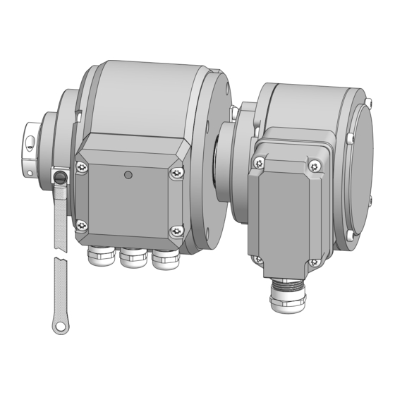
Combination absolute and incremental encoder
Hide thumbs
Also See for Hubner Berlin HMG 11:
- Mounting and operating instructions (52 pages) ,
- Installation and operating instructions manual (48 pages) ,
- Mounting and operating instructions (52 pages)

Related Manuals for Baumer Hubner Berlin HMG 11


Summary of Contents for Baumer Hubner Berlin HMG 11
- Page 1 Montage- und Betriebsanleitung Installation and operating instructions HMG 11 + HOG 10 Kombination Absoluter und inkrementaler Drehgeber Combination Absolute and incremental encoder...
-
Page 2: Table Of Contents
Inhaltsverzeichnis Inhaltsverzeichnis Allgemeine Hinweise ..............................Betrieb in explosionsgefährdeten Bereichen ..................... Sicherheitshinweise ..............................Vorbereitung ..................................Lieferumfang absoluter Drehgeber HMG 11 ..................Lieferumfang inkrementaler Drehgeber HOG 10 ................Zur Montage erforderlich (nicht im Lieferumfang enthalten) ............Zur Demontage erforderlich (nicht im Lieferumfang enthalten) .......... - Page 3 Table of contents Table of contents General notes ................................... Operation in potentially explosive environments ..................Security indications ..............................Preparation ..................................Scope of delivery absolute encoder HMG 11 ..................Scope of delivery incremental encoder HOG 10 ................Required for mounting (not included in scope of delivery) ............
-
Page 4: Allgemeine Hinweise
Allgemeine Hinweise Allgemeine Hinweise Zeichenerklärung: Gefahr Warnung bei möglichen Gefahren Hinweis zur Beachtung Hinweis zur Gewährleistung eines einwandfreien Betriebes des Produkts Information Empfehlung für die Produkthandhabung Die Drehgeber HMG 11 und HOG 10 sind opto-elektronische Prä zi sionsmessgeräte, die mit Sorgfalt nur von technisch qualifiziertem Per s onal gehandhabt werden darf. -
Page 5: General Notes
General notes General notes Symbol guide: Danger Warnings of possible danger General information for attention Informations to ensure correct product operation Information Recommendation for product handling The encoders HMG 11 and HOG 10 are opto electro nic precision measurement devices which must be handled with care by skilled personnel only. -
Page 6: Betrieb In Explosionsgefährdeten Bereichen
Betrieb in explosionsgefährdeten Bereichen Betrieb in explosionsgefährdeten Bereichen Die Geräte entsprechen der Norm EG-Richtlinie 2014/34/EU für explosionsgefährdete Be- reiche. Der Einsatz ist gemäß den Gerätekategorien 3 G (Ex-Atmosphäre Gas) und 3 D (Ex-At- mosphäre Staub) zulässig. Gerätekategorie 3 G: - Ex-Kennzeichnung: II 3 G Ex nA IIC T4 Gc - Normenkonformität: EN 60079-0:2012 + A11:2013... -
Page 7: Operation In Potentially Explosive Environments
Operation in potentially explosive environments Operation in potentially explosive environments The devices comply with the EU standard 2014/34/EU for potentionally explosive atmospheres. They can be used in accordance with equipment categories 3 G (explosive gas atmosphere) and 3 D (explosive dust atmosphere) Equipment category 3 G: - Ex labeling: II 3 G Ex nA IIC T4 Gc... -
Page 8: Sicherheitshinweise
Sicherheitshinweise Sicherheitshinweise Verletzungsgefahr durch rotierende Wellen Haare und Kleidungsstücke können von rotierenden Wellen erfasst werden. • Vor allen Arbeiten alle Betriebsspannungen ausschalten und Maschinen stillsetzen. Zerstörungsgefahr durch elektrostatische Aufladung Die elektronischen Bauteile in den Drehgebern sind empfindlich gegen hohe Spannungen. • Steckkontakte und elektronische Komponenten nicht berühren. • Ausgangsklemmen vor Fremdspannungen schützen. •... -
Page 9: Security Indications
Security indications Security indications Risk of injury due to rotating shafts Hair and clothes may become tangled in rotating shafts. • Before all work switch off all operating voltages and ensure machinery is stationary. Risk of destruction due to electrostatic charge Electronic parts contained in the encoder are sensitive to high voltages. -
Page 10: Vorbereitung
Vorbereitung / Preparation Vorbereitung Preparation Lieferumfang absoluter Drehgeber Scope of delivery absolute encoder HMG 11 HMG 11 13 12 10 11 Gehäuse Housing Durchgehende Hohlwelle Through hollow shaft Klemmring Clamping ring Klemmringschraube Torx M3x12 mm Clamping ring screw torx drive M3x12 mm Drehmomentblech Torque sheet Sechskantschraube M6x18 mm,... -
Page 11: Lieferumfang Inkrementaler Drehgeber Hog 10
Vorbereitung / Preparation Lieferumfang inkrementaler Drehgeber Scope of delivery incremental encoder HOG 10 HOG 10 Gehäuse Housing Einseitig offene Hohlwelle mit Schlüsselfläche Blind hollow shaft with spanner flat SW 17 17 a/f Spannelement Clamping element Halteblech zum Anbau an HMG 11 Stiffener sheet for mounting on HMG 11 Gewindestange M6 (1.4104) Thread rod M6 (1.4104) 4x Sechskantmutter M6, ISO (A2) 4x Hexagon nut M6, ISO (A2) -
Page 12: Zur Montage Erforderlich (Nicht Im Lieferumfang Enthalten)
Vorbereitung / Preparation Zur Montage erforderlich Required for mounting (nicht im Lieferumfang enthalten) (not included in scope of delivery) 24b 24c 3x 3x Drehmomentstütze, als Zubehör erhältlich, Torque arm, available as accessory, Bestellnummer (Länge L, Version): order number (length L, version): 11043628 (67-70 mm, Standard) 11043628... -
Page 13: Zur Demontage Erforderlich (Nicht Im Lieferumfang Enthalten)
Vorbereitung / Preparation Zur Demontage erforderlich Required for dismounting (nicht im Lieferumfang enthalten) (not included in scope of delivery) Montage-/Demontageset als Zubehör erhältlich, Mounting/dismounting kit available as accessory, Bestellnummer 11077087, bestehend aus: order number 11077087, including: Gewindestift M6x10, ISO 7436 (5,8 Vzk) Setscrew M6x10, ISO 7436 (5.8 Vzk) Zylinderschraube M8x45, ISO 4762 (A2) Cylinder screw M8x45, ISO 4762 (A2) -
Page 14: Montage
Montage / Mounting Montage Mounting Schritt 1 Step 1 10 mm 10 mm Schritt 2 Step 2 TX 20 10 mm 10 mm Schritt 3 Step 3 TX 10 * Siehe Seite 7, 8 oder 9 See page 7, 8 or 9 MB097.3 - 11070460 ... -
Page 15: Schritt 4
Montage / Mounting Schritt 4 Step 4 Ansicht 10 mm View All dimensions in millimeters (unless otherwise stated) Motorwelle einfetten! Lubricate motor shaft! Die Antriebswelle sollte einen mög- The drive shaft should have as less lichst kleinen Rundlauffehler aufwei- runout as possible because this can sen, da dieser zu einem Winkelfehler otherwise result in an angle error, see führen kann, siehe Abschnitt 5.7. -
Page 16: Schritt 6 - Drehmomentstütze
Montage / Mounting Schritt 6 - Drehmomentstütze Step 6 - Torque arm Montage Drehmomentstütze The torque arm should be mounted sollte spielfrei erfolgen. Ein Spiel von free from clearance. A play of just beispielsweise ±0,03 entspricht ±0.03 mm, results in concentricity einem Rundlauffehler der Kombination error of the combination of 0.06 mm. -
Page 17: Hinweis Zur Vermeidung Von Messfehlern
Montage / Mounting Hinweis zur Vermeidung von Messfehlern How to prevent measurement errors Für einen einwandfreien Betrieb der To ensure that the combination operates cor- Kombination ist ein korrekter Anbau, ins- rectly, it is necessary to mount it accurately besondere auch der Drehmomentstütze, as described in section 5.1 to 5.6, which in- notwendig, wie beschrieben in Abschnitt cludes correct mounting of the torque arm. -
Page 18: Schritt 7
Montage / Mounting Schritt 7 Step 7 3 mm Schritt 8 Step 8 10 mm 10 mm 17 mm 5 mm 16 * Zul. Anzugsmoment Max. tightening torque = 6 Nm * Siehe Seite 7, 8 oder 9 See page 7, 8 or 9 MB097.3 - 11070460 ... -
Page 19: Schritt 9
Montage / Mounting 5.10 Schritt 9 5.10 Step 9 Zul. Anzugsmoment Max. tightening torque = 2-3 Nm 3 mm * Siehe Seite 8 See page 8 5.11 Anbauhinweis 5.11 Mounting instruction Wir empfehlen, die Kombination so zu It is recommended to mount the montieren, dass der Kabelanschluss combination with cable connection keinem direkten Wassereintritt aus-... -
Page 20: Abmessung
Abmessung / Dimension Abmessung Dimension Positive Drehrichtung Um 90° versetzt gezeichnet Drawing 90° rotated Positive rotating direction All dimensions in millimeters (unless otherwise stated) MB097.3 - 11070460 Baumer_HMG11-HOG10_II_DE-EN (16A2) -
Page 21: Elektrischer Anschluss
Elektrischer Anschluss / Electrical connection Elektrischer Anschluss Electrical connection Profibus DP V0 Profibus DP V0 7.1.1 Kabelanschluss 7.1.1 Cable connection 7.1.1.1 Schritt 1 7.1.1.1 Step 1 TX 20 17 mm TX 20 17 mm * Siehe Seite 7 See page 7 MB097.3 - 11070460 Baumer_HMG11-HOG10_II_DE-EN (16A2) ... - Page 22 Elektrischer Anschluss / Electrical connection 7.1.1.2 Schritt 2 7.1.1.2 Step 2 Kabelschirm Cable shield Ansicht siehe Abschnitt 7.1.2. View see section 7.1.2. 17 mm ø5-9 mm Zur Gewährleistung der angegebenen To ensure the specified protection of Schutzart sind nur geeignete Kabel- the device the correct cable diameter durchmesser zu verwenden.
-
Page 23: Klemmenbelegung Und Schalterstellung
Elektrischer Anschluss / Electrical connection 7.1.2 Klemmenbelegung und Schalterstellung 7.1.2 Terminal assignment and switch settings Ansicht Y Ansicht in Profibus-Haube, siehe Abschnitt 7.1.1.2. View Y View into Profibus cover, see section 7.1.1.2. Negative serielle Datenleitung, Negative serial data transmission, Paar 1 und Paar 2 pair 1 and pair 2 Positive serielle Datenleitung, Positive serial data transmission, Paar 1 und Paar 2... -
Page 24: Funktionen
Elektrischer Anschluss / Electrical connection 7.1.3 Funktionen 7.1.3 Functions Bus-Protokoll Bus-Protokoll Profibus-DP V0 Profibus-DP V0 Profibus Features Device Class 1 und 2 Profibus Features Device Class 1 und 2 Data Exch. Input: Positionswert Data exch. Input: Position value Funktionen functions Output: Preset-Wert Output: Preset value Preset-Wert Mit dem Parameter „Preset“... -
Page 25: Klemmenkasten Hog 10
Elektrischer Anschluss / Electrical connection Klemmenkasten HOG 10 Terminal box HOG 10 7.2.1 Beschreibung der Anschlüsse 7.2.1 Terminal significance Betriebsspannung (für den Drehgeber) +UB; + Voltage supply (for the encoder) Masseanschluss (für die Signale) ; ; GND; 0V Ground (for the signals) Erdungsanschluss (Gehäuse) Earth ground (chassis) Ausgangssignal Kanal 1 K1;... -
Page 26: Kabelanschluss
Elektrischer Anschluss / Electrical connection 7.2.3 Kabelanschluss 7.2.3 Cable connection 7.2.3.1 Schritt 1 7.2.3.1 Step 1 TX 20 22 mm 7.2.3.2 Schritt 2 7.2.3.2 Step 2 TX 10 * Siehe Seite 8 See page 8 MB097.3 - 11070460 Baumer_HMG11-HOG10_II_DE-EN (16A2) - Page 27 Elektrischer Anschluss / Electrical connection 7.2.3.3 Schritt 3 und 4 7.2.3.3 Step 3 and 4 22c * ø9-13 mm Ansicht siehe Abschnitt 7.2.4. Kabelschirm Cable shield View see section 7.2.4. * Siehe Seite 8 oder 9 See page 8 or 9 Zur Gewährleistung der angegebenen To ensure the specified protection Schutzart sind nur geeignete Kabel-...
- Page 28 Elektrischer Anschluss / Electrical connection 7.2.3.4 Schritt 5 7.2.3.4 Step 5 Buchse D-SUB TX 10 zum Anschluss an Drehgebergehäuse siehe Abschnitt 7.2.3.5. Connector D-SUB (female) for connecting to encoder housing see section 7.2.3.5. 22c * 22 mm 7.2.3.5 Schritt 6 7.2.3.5 Step 6 TX 20 Zul.
-
Page 29: Klemmenbelegung
(inputs and outputs). Sensorkabel HEK 8 (Zubehör) Sensor cable HEK 8 (accessory) Es wird empfohlen, das Baumer Hübner Baumer Hübner sensor cable HEK 8 is Sensorkabel HEK 8 zu verwenden oder recommended. As a substitute a shielded ersatzweise ein geschirmtes, paarig ver- twisted pair cable should be used. -
Page 30: Demontage
Demontage / Electrical connection Demontage Dismounting Schritt 1 Step 1 TX 20 TX 20 TX 20 Schritt 2 Step 2 3 mm Schritt 3 Step 3 17 mm 5 mm * Siehe Seite 7, 8 oder 9 See page 7, 8 or 9 MB097.3 - 11070460 ... - Page 31 Demontage / Dismounting Schritt 4 Step 4 10 mm 10 mm 0.8x4 mm Schritt 5 Step 5 17 mm 6 mm Schritt 6 Step 6 * Siehe Seite 8 oder 9 See page 8 or 9 MB097.3 - 11070460 Baumer_HMG11-HOG10_II_DE-EN (16A2) ...
- Page 32 Demontage / Dismounting Schritt 7 Step 7 10 mm 1.6x8 mm Schritt 8 Step 8 TX 10 Schritt 9 Step 9 * Siehe Seite 7 oder 9 See page 7 or 9 MB097.3 - 11070460 Baumer_HMG11-HOG10_II_DE-EN (16A2)
-
Page 33: Zubehör
Zubehör / Accessories Zubehör Accessories • Drehmomentstütze Größe M6 • Torque arm size M6 Bestellnummer: s. Abschnitt 4.3. order number: see section 4.3. • Montageset für Drehmoment- • Mounting kit for torque arm stütze Größe M6 und Erdungs- size M6 and earthing strap, band, Bestellnummer: 11077197 order number: 11077197 •... -
Page 34: Technische Daten
Technische Daten Technische Daten 10.1 Technische Daten - elektrisch • Störfestigkeit: EN 61000-6-2:2005 • Störaussendung: EN 61000-6-3:2007/A1:2011 • Zulassungen: CE, UL-Zulassung / E256710 10.2 Technische Daten - elektrisch (HMG 11) • Betriebsspannung: 9...30 VDC • Betriebsstrom ohne Last: ≤250 mA (pro Schnittstelle) • Initialisierungszeit: ≤200 ms nach Einschalten •... -
Page 35: Technische Daten - Mechanisch
10.4 Technische Daten - mechanisch • Baugröße (Flansch): ø122 mm • Wellenart: ø20 mm (durchgehende Hohlwelle, HMG 11) ø16 mm (einseitig offene Hohlwelle, HOG 10) • Zulässige Wellenbelastung: ≤50 N axial ≤120 N radial • Schutzart DIN EN 60529: IP66 • Betriebsdrehzahl: ≤3500 U/min (mechanisch) • Betriebsdrehmoment typ.: 6 Ncm •... -
Page 36: Technical Data
Technical data Technical data 10.1 Technical data - electrical ratings • Interference immunity: EN 61000-6-2:2005 • Emitted interference: EN 61000-6-3:2007/A1:2011 • Approvals: CE, UL approval / E256710 10.2 Technical data - electrical ratings (HMG 11) • Voltage supply: 9...30 VDC • Consumption w/o load: ≤250 mA (per interface) •... -
Page 37: Technical Data - Mechanical Design
10.4 Technical data - mechanical design • Size (flange): ø122 mm • Shaft type: ø20 mm (through hollow shaft, HMG 11) ø16 mm (blind hollow shaft, HOG 10) • Shaft loading: ≤50 N axial ≤120 N radial • Protection DIN EN 60529: IP66 • Operating speed: ≤3500 rpm (mechanical) • Operating torque typ.: 6 Ncm •... -
Page 38: Anhang: Eu-Konformitätserklärung
Signature/nom/fonction Baumer_HOGSx_OGSx_AMGx_HMGx_DE-EN-FR_CoC_81201176.docm/kwe Baumer Hübner GmbH P.O. Box 126943 ∙ D-10609 Berlin ∙ Max-Dohrn-Str. 2+4 ∙ D-10589 Berlin Phone +49 (0)30 69003-0 ∙ Fax +49 (0)30 69003-104 ∙ info@baumerhuebner.com ∙ www.baumer.com Sitz der Gesellschaft / Registered Office: Berlin, Germany ∙ Geschäftsführer / Managing Director: Dr. Oliver Vietze, Dr. Johann Pohany Handelsregister / Commercial Registry: AG Charlottenburg HRB 96409 ∙... -
Page 39: Inkrementaler Drehgeber Hog 10
Signature/nom/fonction Baumer_HOGx_OGx_POGx_FOGx_HMI_DE-EN-FR_CoC_81201236.docm/kwe Baumer Hübner GmbH P.O. Box 126943 ∙ D-10609 Berlin ∙ Max-Dohrn-Str. 2+4 ∙ D-10589 Berlin Phone +49 (0)30 69003-0 ∙ Fax +49 (0)30 69003-104 ∙ info@baumerhuebner.com ∙ www.baumer.com Sitz der Gesellschaft / Registered Office: Berlin, Germany ∙ Geschäftsführer / Managing Director: Dr. Oliver Vietze, Dr. Johann Pohany Handelsregister / Commercial Registry: AG Charlottenburg HRB 96409 ∙... - Page 40 Baumer Hübner GmbH P.O. Box 12 69 43 · 10609 Berlin, Germany Phone: +49 (0)30/69003-0 · Fax: +49 (0)30/69003-104 info@baumerhuebner.com · www.baumer.com/motion Version: 74364 MB097.3 - 11070460 Baumer_HMG11-HOG10_II_DE-EN (16A2 - 19.08.2016)
Need help?
Do you have a question about the Hubner Berlin HMG 11 and is the answer not in the manual?
Questions and answers