
Related Manuals for 3Com 4210G Series


Summary of Contents for 3Com 4210G Series
- Page 1 3Com Switch 4210G Family Getting Started Guide Manual Version: 6W100-20100203 www.3com.com 3Com Corporation 350 Campus Drive, Marlborough, MA, USA 01752 3064...
- Page 2 3Com Corporation. 3Com Corporation reserves the right to revise this documentation and to make changes in content from time to time without obligation on the part of 3Com Corporation to provide notification of such revision or change.
- Page 3 Host Software Loading 3Com Switch 4210G Family. Introduces the problems that might occur during the installation Maintenance and the booting of the 3Com Switch 4210G Family and the related Troubleshooting solution. Conventions The manual uses the following conventions: Command conventions...
- Page 4 3Com Switch 4210G Family Provide detailed descriptions of command line interface (CLI) Command Reference Guide commands, that you require to manage your switch. Obtaining Documentation You can access the most up-to-date 3Com product documentation on the World Wide Web at this URL: http://www.3com.com.
-
Page 5: Table Of Contents
Table of Contents 1 Product Overview ······································································································································1-1 Overview ·················································································································································1-1 Introduction to Switch 4210G··················································································································1-3 Switch 4210G 24-Port ·····················································································································1-3 Switch 4210G 48-Port ·····················································································································1-4 Switch 4210G PWR 24-Port············································································································1-5 Switch 4210G PWR 48-Port············································································································1-6 Switch 4210G NT 24-Port ···············································································································1-7 Switch 4210G NT 48-Port ···············································································································1-8 Ports ························································································································································1-8 Console Port····································································································································1-8 10/100/1000Base-T Ethernet Port···································································································1-9 1000Base-X SFP Port ·····················································································································1-9... - Page 6 Mounting the Switch on a Workbench ····································································································3-8 Connecting the Grounding Cable············································································································3-9 When a Grounding Strip is Available·······························································································3-9 Where a Grounding Conductor Can be Buried ·············································································3-10 In Other Installation Sites ··············································································································3-11 Connecting the Power Cords ················································································································3-12 Connecting the AC Power Cord ····································································································3-12 Connecting the RPS Power Cord··································································································3-13 Installing an Interface Module ···············································································································3-15 Installing an Interface Card ···········································································································3-15...
- Page 7 Configuration System Failure··················································································································6-4 Troubleshooting when there is no terminal display ·········································································6-4 Troubleshooting when the terminal display is illegible ····································································6-4...
-
Page 8: Product Overview
Product Overview Overview 3Com Switch 4210G Family (hereinafter referred to as the Switch 4210G ) are Layer 3 Gigabit Ethernet switching products developed by 3Com Corporation. (Hereinafter referred to as 3Com). The Switch 4210G are designed as distribution or access devices for intranets and metropolitan area networks (MANs). - Page 9 RPS500-A3 (+12 V/10.5 A output, RPS1000-A3 (–54 V/25 A output, power cable 0404A03C) power cable 0404A053) input : Please use the external RPS power supply units recommended by 3Com only. 4210G 24-Port: 4210G 48-Port: 36 W 55 W Static power...
-
Page 10: Introduction To Switch 4210G
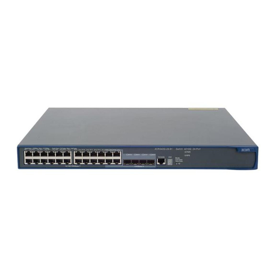
Introduction to Switch 4210G Switch 4210G 24-Port Front Panel Figure 1-1 Front panel of the Switch 4210G 24-Port Ethernet switch (1) 10/100/1000 Base-T auto-sensing Ethernet port (2) 10/100/1000 Base-T auto-sensing Ethernet port status LED (3) 1000Base-X SFP port (4) 1000Base-X SFP port status LED (5) Console port (6) Seven-segment LED (7) Port mode LED (Mode) -
Page 11: Switch 4210G 48-Port
Switch 4210G 48-Port Front Panel Figure 1-3 Front panel of the Switch 4210G 48-Port Ethernet switch (1) 10/100/1000 Base-T auto-sensing Ethernet port (2) 10/100/1000 Base-T auto-sensing Ethernet port status LED (3) Console port (4) Seven-segment LED (5) Port mode LED (Mode) (6) System status LED (PWR) (7) RPS status LED (RPS) (8) Interface module 1 status LED (MOD1) -
Page 12: Switch 4210G Pwr 24-Port
Switch 4210G PWR 24-Port Front Panel Figure 1-5 Front panel of the Switch 4210G PWR 24-Port Ethernet switch (1) 10/100/1000 Base-T auto-sensing Ethernet port (2) 10/100/1000 Base-T auto-sensing Ethernet port status LED (3) 1000 Base-X SFP port (4) 1000Base-X SFP port status LED (5) Console port (6) Seven-segment LED (7) Port mode LED (Mode) -
Page 13: Switch 4210G Pwr 48-Port
Switch 4210G PWR 48-Port Front Panel Figure 1-7 Front panel of the Switch 4210G PWR 48-Port Ethernet switch (1) 10/100/1000 Base-T auto-sensing Ethernet port (2) 10/100/1000 Base-T auto-sensing Ethernet port status LED (3) Console port (4) Seven-segment LED (5) Port mode LED (Mode) (6) System status LED (PWR) (7) RPS status LED (RPS) (8) Interface module 1 status LED (MOD1) -
Page 14: Switch 4210G Nt 24-Port
Switch 4210G NT 24-Port Front Panel Figure 1-9 Front panel of the Switch 4210G NT 24-Port Ethernet switch (1) 10/100/1000 Base-T auto-sensing Ethernet port (2) 10/100/1000 Base-T auto-sensing Ethernet port status LED (3) 1000 Base-X SFP port (4) 1000Base-X SFP port status LED (5) Console port (6) Seven-segment LED (7) Port mode LED (Mode) -
Page 15: Switch 4210G Nt 48-Port
Switch 4210G NT 48-Port Front Panel Figure 1-11 Front panel of the Switch 4210G NT 48-Port Ethernet switch (1) 10/100/1000 Base-T auto-sensing Ethernet port (2) 10/100/1000 Base-T auto-sensing Ethernet port status LED (3) Console port (4) Seven-segment LED (5) Port mode LED (Mode) (6) System status LED (PWR) (7) RPS status LED (RPS) (8) Port status LED mode switching button... -
Page 16: 10/100/1000Base-T Ethernet Port
All SFP transceivers are hot swappable and optional. Therefore, networking is more flexible. You are recommended to use SFP transceivers of 3Com on the Switch 4210G. The types of SFP transceivers may update with time. For information about transceivers, contact... -
Page 17: Combo Port
The SFP port and its corresponding 10/100/1000Base-T autosensing Ethernet port cannot be used together at the same time. For details, refer to the Ethernet Port Configuration part in the Access Volume of the 3Com Switch 4210G Family Configuration Guide. LEDs... -
Page 18: System Status Led
System Status LED The system status LED helps you determine the working status of the switch. Refer to Table 1-6 for the details. Table 1-6 System status LED description Status Description Steady green The switch is started normally. Flashing green (1 Hz) The system is performing power-on self test (POST). -
Page 19: Seven-Segment Led
Table 1-9 Port mode LED description Status Description Steady green Indicates port rate. Flashing green (1 Hz) (supported by Mode Indicates port PoE power supply. PoE switches only) Steady yellow Indicates port duplex mode. Seven-Segment LED The seven-segment LED and the system status LED together indicate the operating status of the device. -
Page 20: 10/100/1000Base-T Auto-Sensing Ethernet Port Status Led
Status Description System status Seven-segment LED LED (PWR) The member ID of the current switch in the IRF system. The LED displays the specific numbers. Switch 4210G NT 24-port and Switch 4210G NT 48-port do not support IRF. The seven-segment LED, the system status LED, and the port mode LED on the Switch 4210G PWR 24-port or Switch 4210G PWR 48-port that supports PoE can display the PoE power consumption percentage of the switch. -
Page 21: 1000Base-X Sfp Port Status Led
Status Description Port mode Ethernet port status Steady green PoE power supply is normal. Power consumption of the device connected to the port Flashing exceeds the upper limit of the power supply consumption of Flashing green (1 Hz) green (1 the port, or the available power of the switch is not enough Hz) (PoE for power supply of the port. -
Page 22: Interface Module Status Led
Interface Module Status LED Table 1-14 Interface module status LED description Mark Status Description Green The interface module is in the slot and operates normally. MOD1 The inserted interface module type is incorrect or the interface Flashing yellow module fails. MOD2 No interface module is installed. -
Page 23: Dual-Port 10 Ge Xfp Interface Module
A short-haul dual-port 10 GE CX4 interface module provides two 10 Gbps electrical ports and supports CX4 electrical and protocol standards. Only 3Com’s CX4 power cables can be used for connecting the CX4 ports. A CX4 cable is hot swappable and its maximum transmission distance is 3 m (9.84 ft.), which is suitable for short-distance connections only. -
Page 24: One-Port 10 Ge Xfp Interface Module
You are recommended to use XFP transceivers of 3Com on the Switch 4210G. The types of XFP transceivers may vary over time. Consult 3Com marketing personnel or technical support personnel to obtain the latest information about XFP transceivers. -
Page 25: Dual-Port 10 Ge Sfp+ Interface Module
insert an XFP transceiver into the port to connect it to another XFP port through an optical fiber. You can select the XFP transceivers list in Table 1-17 as required. Dual-Port 10 GE SFP+ Interface Module Figure 1-20 Dual-port 10 GE SFP+ interface module Figure 1-21 Front panel of dual-port 10 GE SFP+ interface module A dual-port 10 GE SFP+ interface module provides two 10 Gbps SFP+ ports. -
Page 26: Description Of Leds Of Interface Modules
You are recommended to use SFP+ transceivers and SFP+ cables of H3C on the switch 4210G. The types of SFP+ transceivers and SFP+ cables may update with time. For information about transceivers, contact 3Com technical support or marketing staff. Description of LEDs of Interface Modules There is a LED for each port on the interface module panel. -
Page 27: Preparing For Installation
Safety Precautions Before you install or remove any components from the Switch or carry out any maintenance procedures, you must read the 3Com Switch Family Safety and Regulatory Information document enclosed with your switch. To avoid damage to human body and devices, please read the following safety recommendations carefully before installing the Switch 4210G. -
Page 28: Temperature/Humidity
Temperature/Humidity You must maintain a proper temperature and humidity in the equipment room. Long-term high humidity may lead to bad insulation, electricity leakage, mechanical property changes, and metal corrosion. However, if the relative humidity is two low, captive screws may become loose as the result of contraction of insulation washers and static electricity may be produced in a dry environment to jeopardize the circuits on the device. -
Page 29: Laser Safety
Keep the device far from radio transmitting stations, radar stations, and high-frequency devices. Use electromagnetic shielding when necessary, for example, use shielded interface cables. Route interface cables only indoors to prevent signal ports from getting damaged by overvoltage or overcurrent caused by lightning strikes. Laser Safety The Switch 4210G are Class 1 laser devices. -
Page 30: Installing The Switch
When you ask your sales agent to maintain the switch, you must ensure that the dismantlement-preventive seal on a mounting screw of the 3Com switch chassis is intact. If you want to open the chassis, you should contact the agent for permission. Otherwise, you will bear any consequence resulted from your actions without permission. -
Page 31: Installing The Switch Into A 19-Inch Rack Using Mounting Brackets
The Switch 4210G (excluding Switch 4210G NT 24-Port and Switch 4210G NT 48-Port) support IRF. For details about implementation of the IRF system and installation procedures, refer to Installation Flow for an IRF. Installing the Switch into a 19-Inch Rack Using Mounting Brackets The installation methods of a switch depend on the depth and width of the switch. -
Page 32: Use Front Mounting Brackets To Install A Switch
Figure 3-3 Appearance of a rear mounting bracket (1) Screw hole used to fix the mounting bracket to the cabinet (Use one M6 screw) For the selection of front and rear mounting brackets, see Table 3-2. Table 3-2 Selection of mounting bracket for Switch 4210G Configuration Configuration Physical dimensions... -
Page 33: Use Front Mounting Brackets And A Tray To Install A Switch
Figure 3-4 Fix front mounting brackets (1) (1) Front panel of the switch Step4 Place the switch horizontally in a proper position, and fix the other end of mounting brackets to the front brackets with screws and captive nuts, as shown in Figure 3-5. -
Page 34: Use Front And Rear Mounting Brackets To Install A Switch
Step5 Place the switch on the tray horizontally, slide the tray into the cabinet, and fix the other end of mounting brackets to the front brackets with crews and captive nuts, as shown in Figure 3-5. Use Front and Rear Mounting Brackets to Install a Switch Only the Switch 4210G PWR 24-Port and Switch 4210G PWR 48-Port support installation using front mounting brackets together with rear mounting brackets. - Page 35 Figure 3-7 Fix rear mounting brackets (1) Rear square-holed post (2) Rear mounting bracket Step6 Hold the bottom of the switch with one hand and the front part of the switch with the other hand, and push the switch into the cabinet gently, as shown in Figure 3-8.
- Page 36 Figure 3-9 Effect diagram of front and rear mounting bracket installation (1) (1) Rear panel (2) Rear square-holed post (3) Load-bearing screw (4) Rear mounting bracket Step7 Fix the other end of the front mounting brackets to the front brackets with screws and captive nuts and ensure that front and rear mounting brackets have fixed the switch in the cabinet securely, as shown in Figure 3-10.
-
Page 37: Mounting The Switch On A Workbench
Figure 3-10 Effect diagram of front and rear mounting bracket installation (2) (1) Load-bearing screw (2) Rear mounting bracket (3) Front panel (4) Screw used to fix front mounting brackets to front brackets (5) Front mounting bracket (6) Front square-holed post Mounting the Switch on a Workbench In many cases, standard 19-inch racks are not available. -
Page 38: Connecting The Grounding Cable
Connecting the Grounding Cable Correctly connecting the chassis grounding cable is crucial to the lightning protection and electromagnetic susceptibility (EMS) of a switch. The power and grounding terminals in this section are for illustration only. The power input end of the switch is connected with a noise filter, whose central ground is directly connected to the chassis, forming the so-called chassis ground (commonly known as PGND). -
Page 39: Where A Grounding Conductor Can Be Buried
Step1 Cut the PGND cable to a proper length according to the distance between the switch and the grounding strip. Step2 Peel 5 mm (0.20 in.) of insulation sheath using a wire stripper, and then insert the naked metal part through the black insulation covering into the end of the OT terminal. -
Page 40: In Other Installation Sites
Figure 3-13 Ground the switch by burying the grounding conductor into the earth (1) Grounding screw (2) PGND cable (3) Earth (4) Joint (5) Grounding conductor (6) Switch rear panel In Other Installation Sites For an AC-powered switch, if neither of the above-mentioned two conditions is available, ground the switch through the PE wire of the AC power supply. -
Page 41: Connecting The Power Cords
Connecting the Power Cords Make sure that the ground wire has been properly connected before powering on the switch. Table 3-3 Power cord connection methods of the Switch 4210G Power supply Switch module Connection method mode Switch 4210G 24-Port AC power supply Connecting the AC Power Cord Switch 4210G 48-Port Connect RPS power cords of the Switch 4210G... -
Page 42: Connecting The Rps Power Cord
Figure 3-16 Connect an AC power cord to a horizontal AC power socket (2) Figure 3-17 Connect an AC power cord to a vertical AC power socket (1) Figure 3-18 Connect an AC power cord to a vertical AC power socket (2) Connecting the RPS Power Cord Connect RPS power cords of the Switch 4210G (excluding Switch 4210G PWR 24-Port and Switch 4210G PWR 48-Port) - Page 43 Figure 3-19 Connect an RPS power cord (1) Step3 Keep the upside of the +12 VDC RPS plug on top and plug it in the RPS DC receptacle (see callout 1 in Figure 3-20). (If you plug it with the upside down, the insertion is not smooth because of the specific structure design of the RPS DC receptacle and the RPS plug.) Step4 Use a flat-blade screwdriver to fix the two screws on the RPS plug clockwise to secure the plug to the RPS DC receptacle (see callout 2 in...
-
Page 44: Installing An Interface Module
Figure 3-21 Connect an RPS power cord to the Switch 4210G PWR 24-Port and Switch 4210G PWR 48-Port Step4 Connect the other end of the RPS DC power cord to the external RPS power supply system. Step5 Check whether the RPS LED on the front panel of the switch is ON. If the LED is ON, it shows the power cord is properly connected. -
Page 45: Removing An Interface Module
Figure 3-23 Install an interface module (2) Keep the removed filler panel properly for future use. When tightening the fastening screws at both sides of the optional module with a screwdriver or an electric screwdriver, make sure that the torque is not bigger than 0.4 N-m. Removing an Interface Module Step1 Wear an ESD-preventive wrist strap, ensure a good skin contact and make sure that the ESD-preventive wrist strap is properly grounded. -
Page 46: Removing Dedicated Cx4/Sfp+ Cable
The installation and removal of dedicated CX4 cables and SFP+ cables are similar. This section describes the installation and removal of the dedicated CX4 cable for illustration. Make sure that you have installed a CX4/SFP+ interface module before installing CX4/SFP+ cables. Step1 Put on an ESD-preventive wrist strap and verify the ESD-preventive wrist strap properly grounded. -
Page 47: Installation Flow For An Irf
Installation Flow for an IRF Figure 3-24 Installation flow for an IRF Table 3-4 Description of the installation flow for an IRF of switches Task Remarks Take the following into consideration: Number of IRF members and the bandwidth Draw a plan for Interface modules and cables an IRF with Physical connection mode( daisy chain connection or ring connection) -
Page 48: Drawing A Plan For An Irf With Switches
Module. modules Configure For details about the IRF function, see IRF Configuration in the System software for the Volume of the 3Com Switch 4210G Family Configuration Guide. IRF members Power off the — switches Use cables to connect 10 G ports of the interface modules:... - Page 49 Configure the physical connection mode IRF supports two physical connection modes: daisy chain connection and ring connection. A ring connection is more reliable than a daisy chain connection. The failure of one link in a ring connection does not affect the function and performance of the IRF, whereas the failure of one link in a daisy chain connection causes the split of the IRF.
- Page 50 When 2-port interface modules are used to constitute an IRF of switches and the ports are not assigned to any aggregation group, ports of the interface module in slot 1 (MOD 1) can be connected to ports of MOD 1 or MOD 2. However, the left port can be connected to only the right port of another interface module, that is, two ports at the same side cannot be connected, as shown Figure 3-27.
-
Page 51: Verifying The Installation
Figure 3-29 Cable connections for an IRF with 1-port interface modules Verifying the Installation Check whether the selected power is the same as the power label on the switch; Check whether the ground wire is connected; Check whether the power cords are connected correctly; Check whether all the interface cables are routed indoors. -
Page 52: Starting And Configuring The Switch
Starting and Configuring the Switch Setting up the Configuration Environment Set up the configuration environment as follows: Connect a terminal (a PC in this example) to the console port on the switch with a console cable. Figure 4-1 Network diagram for configuration environment setup Connecting the Console Cable Console Cable A console cable is an 8-core shielded cable. -
Page 53: Connection Procedure
RJ-45 Signal Direction DB-9 ← → → → → Connection Procedure When you want to use the terminal to configure the switch, follow these steps to connect a terminal device to the switch using the console cable: Step1 Plug the DB-9 female connector of the console cable to the serial port of the console terminal or PC. Step2 Connect the RJ-45 connector of the console cable to the console port of the switch. - Page 54 Data bits: 8 Parity: None Stop bits: 1 Flow control: None Emulation: VT100 The specific procedure is as follows: Step1 Select Start > Programs > Accessories > Communications > HyperTerminal to enter the HyperTerminal window. The Connection Description dialog box appears, as shown below. Figure 4-3 Connection description of the HyperTerminal Step2 Type the name of the new connection in the Name text box and click OK.
- Page 55 Step3 Click OK after selecting a serial port. The following dialog box appears. Set Bits per second to 19200, Data bits to 8, Parity to None, Stop bits to 1, and Flow control to None. Figure 4-5 Set the serial port parameters Step4 Click OK after setting the serial port parameters and the system enters the HyperTerminal window shown below.
-
Page 56: Booting The Switch
All the Switch 4210G have the same Boot ROM display style. This document uses the Boot ROM display of Switch 4210G 24-Port as an example: Starting..************************************************************************* Switch 4210G 24-Port BOOTROM, Version 510 ************************************************************************* Copyright (c) 2004-2009 3Com Corporation and its licensors. - Page 57 Creation date : May 18 2009, 17:01:57 CPU Clock Speed : 264MHz BUS Clock Speed : 33MHz Memory Size : 128MB Mac Address : 001cc5bc3111 Press Ctrl-B to enter Boot Menu... 1 The last line asks whether you want to enter the Boot Menu. The system waits one second for your response.
-
Page 58: Changing The Startup Mode
Item Description 4. Delete file from flash Delete files from the flash memory 5. Modify bootrom password Modify the Boot ROM password 6. Enter bootrom upgrade menu Enter the Boot ROM update menu Skip the current configuration file (this configuration is 7. - Page 59 Enter 0. The system reboots in normal mode and displays the following information: Starting..************************************************************************* Switch 4210G 24-Port BOOTROM, Version 510 ************************************************************************* Copyright (c) 2004-2009 3Com Corporation and its licensors. Creation date : May 18 2009, 17:01:57 CPU Clock Speed : 264MHz...
- Page 60 BUS Clock Speed : 33MHz Memory Size : 128MB Mac Address : 001cc5bc3111 Press Ctrl-B to enter Boot Menu... 0 In normal startup mode, the waiting time here is five seconds. If you press Ctrl + B within five seconds, the Boot Menu is displayed.
- Page 61 You can configure the switch now. The Switch 4210G provide abundant command views. For detailed descriptions about the configuration commands and CLI, refer to 3Com Switch 4210G Family Configuration Guide, 3Com Switch 4210G Family Command Reference Guide. 4-10...
-
Page 62: Boot Rom And Host Software Loading
Before loading the software, make sure that your terminal is correctly connected to the switch to insure successful software loading. Boot Menu Starting..************************************************************************* Switch 4210G 24-Port BOOTROM, Version 510 ************************************************************************* Copyright (c) 2004-2009 3Com Corporation and its licensors. Creation date : May 18 2009, 17:01:57... - Page 63 CPU Clock Speed : 264MHz BUS Clock Speed : 33MHz Memory Size : 128MB Mac Address : 001cc5bc3111 Press Ctrl-B to enter Boot Menu... 1 Press Ctrl + B. The system displays: Password : To enter the Boot Menu, you must press Ctrl + B within one second after the information “Press Ctrl-B to enter Boot Menu...”...
-
Page 64: Loading Software Using Xmodem Through Console Port
The loading process of the Boot ROM software is the same as that of the host software, except that during the Boot ROM loading process, you must enter the different digit after entering the Boot Menu and the system gives somewhat different prompts. The following text mainly describes the Boot ROM loading process. - Page 65 Task Remarks Restart the switch to make the updated Boot Required ROM file effective Enter the Boot ROM update menu on the switch Enter the Boot ROM menu, and then enter 6 after the system displays “Enter your choice(0-9):” to enter the Boot ROM update menu.
- Page 66 Change the rate of the serial port on the terminal To ensure communication between the terminal and the switch, the baud rate of the serial port on the terminal should be consistent with that of the console port on the switch. Step1 Select Call >...
- Page 67 Figure 5-3 Modify the baud rate Step3 Select Call > Call to reestablish the connection. Figure 5-4 Reestablish the connection The new settings can take effect only after you reestablish the connection. Download the Boot ROM file Step1 Press Enter in the HyperTerminal window to start downloading the program. The system displays the following information: CCCCCCCCCCCCCCCCCC Press Ctrl + X to quit downloading files;...
- Page 68 Step2 Select Transfer > Send File in the HyperTerminal’s window. Click Browse in the pop-up dialog box (as shown in Figure 5-5) to select the application file to be downloaded (for example, bootrom.btm), and select Xmodem from the Protocol drop-down list. Figure 5-5 Send file dialog box Step3 Click Send.
-
Page 69: Loading Software Using Tftp Through Ethernet Port
Restore the download rate to the default Set the baud rate to 19200 bps (refer to Change the rate of the serial port on the terminal on page detailed operation). Restart the switch to make the updated Boot ROM file effective Press Enter in the HyperTerminal window to return to the Boot ROM update menu. - Page 70 Figure 5-7 Load Boot ROM software through TFTP/FTP You can use one PC as both configuration device and TFTP server. The TFTP/FTP server program is not provided with the Switch 4210G. Make sure that it is available by yourself. Step2 Run TFTP Server on the server connected with the switch’s Ethernet port, and specify the path of the application file to be downloaded.
-
Page 71: Loading Software Using Ftp Through Ethernet Port
Loading........done Bootrom updating..done! BOOT MENU 1. Download application file to flash 2. Select application file to boot 3. Display all files in flash 4. Delete file from flash 5. Modify bootrom password 6. Enter bootrom upgrade menu 7. Skip current configuration file 8. - Page 72 Step1 Connect an Ethernet port (GigabitEthernet 1/0/25, for example) of the switch to the server (whose IP address is available) that provides the file (usually the .bin file or the .btm file) to be downloaded, and connect the console port of the switch to a PC, as shown in Figure 5-7.
-
Page 73: Loading Software Through Cli
BOOT MENU 1. Download application file to flash 2. Select application file to boot 3. Display all files in flash 4. Delete file from flash 5. Modify bootrom password 6. Enter bootrom upgrade menu 7. Skip current configuration file 8. Set bootrom password recovery 9. -
Page 74: Loading Software Using Tftp
<Sysname> ftp 202.10.10.53 Trying ... Press CTRL+K to abort Connected. 220 WFTPD 2.0 service (by Texas Imperial Software) ready for new user User(none):4210G 331 Give me your password, please Password: 230 Logged in successfully [ftp] get 4210G.bin [ftp] get 4210G.btm [ftp] bye Step2 Update the Boot ROM program on the switch. -
Page 75: Maintenance And Troubleshooting
Maintenance and Troubleshooting Software Loading Failure If software loading fails, the system keeps running in original version. In this case, check if the physical ports are properly connected. If the ports are not properly connected, reconnect them correctly and restart the loading procedure. If the ports are properly connected, check the loading procedure information displayed on the HyperTerminal for input errors. -
Page 76: Power Supply Failure
Power Supply Failure The Switch 4210G use fixed power modules. Each of the Switch 4210G has three input modes, namely, AC input, RPS input and both. You can check whether the power system of the switch fails by viewing the system status LED (PWR) and RPS status LED (RPS) on the front panel of the switch. -
Page 77: Fan Failure
Check whether the AC power cord is well connected to the switch, whether the AC receptacle on the switch and the AC power socket are faulty. Check whether the AC external power supply system is normal. Check whether the switch is well connected to the external RPS power supply. Check whether the external RPS power supply works normally. - Page 78 The Switch 4210G switches use fixed fans. If a fixed fan failure occurs, you cannot solve the problem by yourself. Please contact your sales agent or service engineer. To ensure the normal operation of the switch, you need to contact the local sales agent or service engineer as soon as possible when a fixed fan failure occurs.
Need help?
Do you have a question about the 4210G Series and is the answer not in the manual?
Questions and answers