
Related Manuals for RKI Instruments SD-1GH


Summary of Contents for RKI Instruments SD-1GH
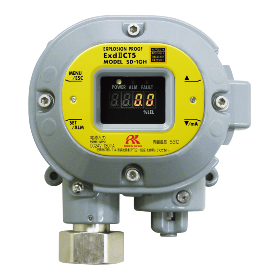
- Page 1 Smart Transmitter/Gas Detector Head SD-1GH Operating Manual Part Number: 71-0531 Revision: P2 Released: 10/28/20...
- Page 2 Operating Precautions This instrument is a gas detector that detects combustible gases in the air and triggers a gas alarm. The gas detector is a safety unit, not an analyzer or densitometer which performs quantitative/qualitative analysis/measurement for gases. Please fully understand the following points before using it, so that it can be used properly. This detector may be interfered by gases and vapors other than the gas to be detected.
-
Page 3: Table Of Contents
10-4. TIIS Outline Drawing ....................55 10-5. Full Scale, Alarm Points, Increments ............... 55 10-6. Detection Principle ....................56 11 Calibration Parts List ......................57 12 Replacement Parts List ....................... 58 13 Definition of Terms ....................... 59 SD-1GH - 3 -... -
Page 4: Outline Of The Product
Outline of the Product 1-1. Preface Thank you for choosing the SD-1GH. Please check that the model number of the product you purchased is included in this manual’s specifications. This manual explains how to use the detector. It contains information required for using the detector properly. -
Page 5: Confirming Standards And Explosion-Proof Specification
Please refer to the Declaration of Conformity at the end of this manual if you have CE marking type. You can confirm detector specification on the name plate as follows. Ex marking TIIS certificate CE marking ATEX/IECEx, CE marking type name plate TIIS type name plate SD-1GH - 5 -... -
Page 6: Important Notices On Safety
Check the atmosphere for freshness before performing a zero adjustment. If gases exist in the atmosphere, the adjustment cannot be performed properly. Response to gas alarm A gas alarm condition indicates that there are extreme dangers. Take proper actions based on your judgment. SD-1GH - 6 -... -
Page 7: Precautions
Perform regular maintenance. Since this is a safety unit, regular maintenance must be performed to ensure safety. Continuing to use the detector without performing maintenance will deteriorate the sensitivity of the sensor, thus resulting in inaccurate gas detection. SD-1GH - 7 -... -
Page 8: Safety Information
2-4. Safety Information Necessary information for explosion proof construction of Model SD-1GH. The Model SD-1GH is a fixed-mount, continuous-monitoring detector head and provides a 4-20mA signal proportional to the target gas reading for use by a gas monitoring controller, recording device, or programmable controller. - Page 9 Contact output (contact capacity): AC250V 0.5A (load resistance) DC30V 0.5A (load resistance) Applicable Standard JNIOSH-TR-NO. 43(2008) Installation Installation Diagram Hazardous Location Nonhazardous Location ← → (Zone 1) Indicator Gas Detector(SD-1GH) + + - - CVVS Cable Signal Signal SD-1GH - 9 -...
-
Page 10: Product Components
Product Components 3-1. Main Unit and Standard Accessories <ATEX/IECEx Specification> <TIIS Specification> <Standard Accessories> • Operating manual • Dedicated handling lever (used for the wiring) • Dedicated control key SD-1GH - 10 -... -
Page 11: Parts Description
Turns yellow when a detector abnormality is detected. Concentration value display Displays the gas concentration. CAUTION Use the supplied dedicated control key to operate the detector. If anything else is used, key operations cannot be accepted properly. SD-1GH - 11 -... -
Page 12: Electric Diagram
(four-digit) (CPU) Gas alarm contact (ALARM) Magnetic operation part Contact activation (MENU/ESC) (▲) (▼) (SET) • De-energized (De-energized in a normal environment) • ON-ALARM (Closed contact during alarm) Sensor Transmitter • 4 – 20 mA transmission SD-1GH - 12 -... -
Page 13: How To Use
Condensation may form inside the detector or the detector cannot adjust to sudden changes in the temperature. Keep the detector (and its cables) away from noise sources. When selecting installation points, avoid a place where high-frequency/high-voltage devices exist. SD-1GH - 13 -... -
Page 14: Precautions For System Designing
UPS outside the blackout restart the detector.) detector. Example of actions Do not use it with a power supply that Others has a large power load or Use a line filter to avoid the noise high-frequency noise. source. SD-1GH - 14 -... - Page 15 • It may be recommended that the surge absorbing part be attached to the contact for certain load conditions. It must be attached to an appropriate position by checking how the load is activated. SD-1GH - 15 -...
-
Page 16: How To Install
Do not install the detector in a place where maintenance involves dangers, for example, near a high-voltage cable. SD-1GH - 16 -... -
Page 17: Wiring
From Φ9.6 to less than Φ10.5 Φ11 Φ12 Φ10.8 From Φ10.5 to less than Φ11.5 Φ12 Φ12 Φ11.8 From Φ11.5 to less than Φ12.5 Φ13 Φ14 Φ12.8 From Φ12.5 to less than Φ13.0 Φ13.5 Φ14 Φ13.8 φ23 SD-1GH - 17 -... - Page 18 However, it depends on cables to be used. Connection conditions • Cables: 0.25 - 2.5 mm • Bare wire length: 8 - 9 mm • Connecting tool: Dedicated handling lever (accessory) or driver (edge 3.5 x 0.5 mm) SD-1GH - 18 -...
- Page 19 • Bar terminal (ferrule): Model 216 Series (manufactured by WAGO) • Crimping tool: Model VarioCrimp 4 (206-204) (manufactured by WAGO) CAUTION A bar terminal of the specified model must be used. Using other bar terminals invalidates the warranty of the performance. SD-1GH - 19 -...
- Page 20 • Ensure the tightening torque for the cable gland and seal plug to be 40 N·m or larger. • If it is difficult to tighten the cable gland, grease its screw part and then tighten it with the tool. SD-1GH - 20 -...
- Page 21 (round) wiring hole until it reaches the finger to lower the spring. deepest point. 3. Once the lever is released, the wire is secured. 4. Pull the wire gently to make sure it is secure. SD-1GH - 21 -...
- Page 22 <Wiring Diagrams> Connecting to a Controller SD-1GH 1 2 3 4 5 RM-593, etc. +24 V Connecting to a DCS or PLC SD-1GH 1 2 3 4 5 Power supply Relay terminal plate (24 VDC) + - Upper unit (DCS, PLC) -...
-
Page 23: How To Operate
The detector is restarted blinking after recovering from fault. MENU/ESC (long pressing) <<User Mode>> <<Gas Alarm>> <<Fault Status>> <<Maintenance Mode>> WARNING When the detector enters other mode from Detection Mode while an alarm is activated, the alarm is reset. SD-1GH - 23 -... -
Page 24: Starting The Detector
1 - 24 hours 4 hours 1 – 3 days 24 hours 3 – 10 days 2 days 10 – 31 days 7 days 1 - 3 months 14 days 3 months or more 1 month SD-1GH - 24 -... -
Page 25: Modes
2-4.F Sensor Fault Alarm Pattern Setting 2-4.H LOAD Voltage Adjustment Display various electrical settings. Display This is not typically used by the user. Switch to Factory Not used. Mode Switch to User Returns to the user mode. Mode SD-1GH - 25 -... -
Page 26: User Mode
Zero Adjustment => P27 1-1. Zero Adjustment Perform the zero adjustment. Setting Display => P28 1-2. Various Setting Display Show various setting values. 1-3. Mode Switching. => P34 Switch to Maintenance Mode. To 1-0 SD-1GH - 26 -... - Page 27 FAIL and automatically returns to 1-1. Return to 1-1. NOTE • If the zero calibration fails, the detector returns to 1-1 after FAIL is displayed. In this case, the zero adjustment has not been completed. SD-1GH - 27 -...
-
Page 28: Turning Off The Detector
Decide whether the power can be turned off by checking the operation of the devices connected to the external output or external contact output terminal of the detector. • If the alarm contact is energized (option), it is activated when the detector is turned "OFF". SD-1GH - 28 -... -
Page 29: Operations And Functions
The contact activation automatically resets when the gas concentration drops below the alarm setpoint value. Alarm setpoint Time Alarm lamp (ALM) Alarm contact (terminal plate 4, 5) Alarm delay time (2 seconds) SD-1GH - 29 -... -
Page 30: Fault Alarm Activation
HOLD setting: The previous value retained 4 - 20 mA setting: 4 - 20 mA (concentration output) Alarm Test Output ON setting: 4 - 20 mA (concentration output) Output OFF setting: 4 mA Fault Alarm 0.5 mA (Fixed) SD-1GH - 30 -... - Page 31 In particular, when the detector is started or the specification is changed, be careful about 4-20 mA output setting. Understand how the detector functions, and take actions, if necessary, so that the signal receiver side can prepare to avoid false alarms. SD-1GH - 31 -...
-
Page 32: Suppression Function
• In Maintenance Mode, this function is disabled and the fluctuation around zero is displayed. CAUTION A reading above zero is suppressed with the 10% FS suppression. A reading that is 10% FS or more below zero is displayed as "-0.0". The detector needs a zero adjustment and span adjustment. SD-1GH - 32 -... -
Page 33: Maintenance
Check that the concentration Display Check display value is zero. If the reading is not zero, perform a zero adjustment and span adjustment. Span Perform a span adjustment using − − Adjustment calibration gas. SD-1GH - 33 -... -
Page 34: Maintenance Mode
2-4.F Sensor Fault Alarm Pattern Setting 2-4.H LOAD Voltage Adjustment Display various electrical settings. Display This is not typically used by the user. Switch to Factory Not used. Mode Switch to User Mode Returns to User Mode. SD-1GH - 34 -... - Page 35 Initialize the zero/span adjustment after the sensor is replaced. Environmental 2-4. Environmental Setting Setting Set various operations and => P42 functions. 2-4.0 and 2-4.3 to 2-4.H are factory-set. They are not typically used by the user. SD-1GH - 35 -...
- Page 36 This is not used by the user. 2-6. Enter Factory Mode. This is not used by the user. rET. is displayed. 2-7. Press the SET key Return to User Mode. again to return to User Mode. To 2-0. Test Mode SD-1GH - 36 -...
- Page 37 Test Mode, it automatically returns to Detection Mode in ten hours.) • In Alarm Test Mode, the gas concentration equal to the reading is output depending on the Maintenance Mode setting. Take actions, if necessary, so that the signal receiver side can prepare for false alarms. SD-1GH - 37 -...
- Page 38 To 2-0.0 WARNING Because the contact and gas concentration output can be activated by a gas test, depending on the Maintenance Mode setting, be careful when performing this test. SD-1GH - 38 -...
- Page 39 To 2-0.1 WARNING Because the contact and gas concentration output can be activated by an alarm test, depending on the Maintenance Mode setting, be careful when performing this test. SD-1GH - 39 -...
- Page 40 FAULT) and to display a gas concentration of 8.8.8.8. Return to OFF and press the SET key to cancel the test. (Pressing the MENU/ESC key also cancels the test and returns the unit to the original state.) SD-1GH - 40 -...
- Page 41 When abnormalities are found in the memory, F-RA is displayed for a RAM fault, and F-RO is displayed for a ROM fault. If there is a fault in the RAM and the ROM, F-RA and F-RO alternate. SD-1GH - 41 -...
- Page 42 Alarm Setpoint Setting Select the number by pressing the ▲ or ▼ key, and then press the SET key to confirm the value. (Press the Return to 2-4.2. MENU/ESC key to go back to the original state.) SD-1GH - 42 -...
-
Page 43: Performing A Calibration
Detection Mode While in Detection Mode, press and hold the MENU/ESC key for three seconds. User Mode 1-0. ROM/SUM displays. Scroll to the 1-3 Mode Switching item. SD-1GH - 43 -... - Page 44 * If the zero adjustment fails, it automatically returns to 2-1 after FAIL is displayed. Return to 2-1. NOTE • If the zero calibration fails, the detector returns to 2-1 after FAIL. In this case, the zero adjustment has not been completed. SD-1GH - 44 -...
- Page 45 If the span adjustment cannot be performed even when there is no mistake or after recalibration, the gas sensor life might have expired. Replace the sensor as described on page 46. SD-1GH - 45 -...
-
Page 46: Parts Replacement
7-4. Parts Replacement <Sensor Replacement> 1. Turn off power to the SD-1GH. 2. Use a 6 mm hexagonal screwdriver (Allen wrench) to unscrew the sensor guard. 3. Unplug the old sensor. 4. Line up the pins on the new sensor with the sockets in the sensor slot. The longest sensor pin faces to the front of the unit. - Page 47 100 ppm Isobutane: 75 ppm C5H10O2 (Propyl acetate) 1000 ppm IPA: 1000 ppm C6H6 (Benzene) 100 ppm Isobutane: 250 ppm 500 ppm Isobutane: 1600 ppm C6H14 (Hexane) 500 ppm Hexane: 500 ppm 3000 ppm Hexane: 3000 ppm SD-1GH - 47 -...
- Page 48 3. Install the new O-ring in the groove. Make sure it sits flat. 4. Close the j-box lid and tighten the screws to a torque of 215.6 ± 24.5 N cm (22.0 ± 2.50 kgf cm). SD-1GH - 48 -...
-
Page 49: Storage, Relocation, And Disposal
For information on wiring, see 4-5. Wiring on page 17. The unpowered time must be minimized when the detector is relocated. CAUTION • When using a relocated or stopped/stored detector again, perform a gas calibration. 8-3. Disposal When disposing of the detector, treat it as industrial waste in accordance with the local regulations. SD-1GH - 49 -... -
Page 50: Troubleshooting
Faults of the sensor Replace the sensor. The rated voltage is not Check the power supply and supply the supplied to the detector. rated voltage. System abnormalities Abnormalities in the detector’s ROM, RAM, or Please contact RKI. EEPROM SD-1GH - 50 -... - Page 51 Deteriorated sensor Slow response Replace the sensor. sensitivity Improper calibration Use the proper calibration gas. gas concentration Span adjustment impossible Deteriorated sensor Replace the sensor. sensitivity SD-1GH - 51 -...
-
Page 52: Product Specifications
Product Specifications 10-1. ATEX/IECEx Specifications Model SD-1GH Detection principle Semiconductor Gas to be detected Combustible/toxic gas Concentration display Seven-segment LED (four-digit) Detection range See page 55 Display resolution See page 55 Detection method Diffusion type Alarm setpoint See page 55... -
Page 53: Atex/Iecex Outline Drawing
10-2. ATEX/IECEx Outline Drawing SD-1GH - 53 -... -
Page 54: Tiis Specifications
10-3. TIIS Specifications Model SD-1GH Detection principle Semiconductor Gas to be detected Combustible/toxic gas Concentration display Seven-segment LED (four-digit) Detection range See page 55 Display resolution See page 55 Detection method Diffusion type Alarm setpoint See page 55 Power display... -
Page 55: Tiis Outline Drawing
5 ppm CH4 (Methane) 2000 ppm 500 ppm 10 ppm EO (Ethylene oxide) 1000 ppm 200 ppm 5 ppm MEK (Methyl ethyl ketone) 500 ppm 200 ppm 5 ppm R404a 2000 ppm 500 ppm 10 ppm SD-1GH - 55 -... -
Page 56: Detection Principle
10-6. Detection Principle Metal dioxide can measure a gas concentration based on changes in the electric conductivity of semiconductor caused by gas adsorbed on its surface. RL: Load resistance, Vo: Output voltage VH: Heater voltage, Vs: Sensor voltage SD-1GH - 56 -... -
Page 57: Calibration Parts List
IPA (isopropyl alcohol): 1000 ppm in air, 103 liter calibration cylinder 81-0035RK-03 IPA (isopropyl alcohol): 2000 ppm (10% LEL) in air, 17 liter calibration cylinder 81-0014RK Zero air, 34 liter steel calibration cylinder 81-0076RK-01 Zero air, 103 liter calibration cylinder 81-0076RK-03 SD-1GH - 57 -... -
Page 58: Replacement Parts List
CH4 (Methane), 0 – 2000 ppm replacement sensor SG-8511 EO (Ethylene oxide), 0 – 1000 ppm replacement sensor SG-8563 MEK (Methyl ethyl ketone), 0 – 500 ppm replacement sensor SG-8521 R404a, 0 – 2000 ppm replacement sensor SG-8521 SD-1GH - 58 -... -
Page 59: Definition Of Terms
A function which temporarily suspends alarm activation to prevent a false Alarm delay time alarm caused by noise. The gas detection function is temporarily suspended during maintenance, etc. INHIBIT This is also called "point skip", which has the same function. SD-1GH - 59 -... - Page 60 SD-1GH - 60 -...
Need help?
Do you have a question about the SD-1GH and is the answer not in the manual?
Questions and answers