
Related Manuals for RKI Instruments Eagle Series


Summary of Contents for RKI Instruments Eagle Series
- Page 1 Instruction Manual Eagle Series Portable Multi-Gas Detector Part Number: 71-0028RK Revision: S Released: 4/13/22 1.800.561.8187 information@itm.com www. .com...
- Page 2 WARNING Read and understand this instruction manual before operating instrument. Improper use of the gas monitor could result in bodily harm or death. Periodic calibration and maintenance of the gas monitor is essential for proper operation and correct readings. Please calibrate and maintain this instrument regularly! Frequency of calibration depends upon the type of use you have and the sensor types.
- Page 3 RKI to be free from defects in materials and workmanship for a period of one year from date of shipment from RKI Instruments, Inc. Any parts found defective within that period will be repaired or replaced, at our option, free of charge. This warranty does not apply to items that are subject to deterioration or consumption in normal service, and which must be cleaned, repaired, or replaced routinely.
-
Page 4: Table Of Contents
Table of Contents Introduction ........... . . 8 Overview. - Page 5 Setup Mode........... . . 25 Tips for Using Setup Mode.
- Page 6 Appendix D: Carbon Dioxide Sensors ......57 Specifications ............57 Description .
- Page 7 Appendix J: Eagle Transformer Gas Tester Model TRB ....74 Description ............74 Operation .
-
Page 8: Introduction
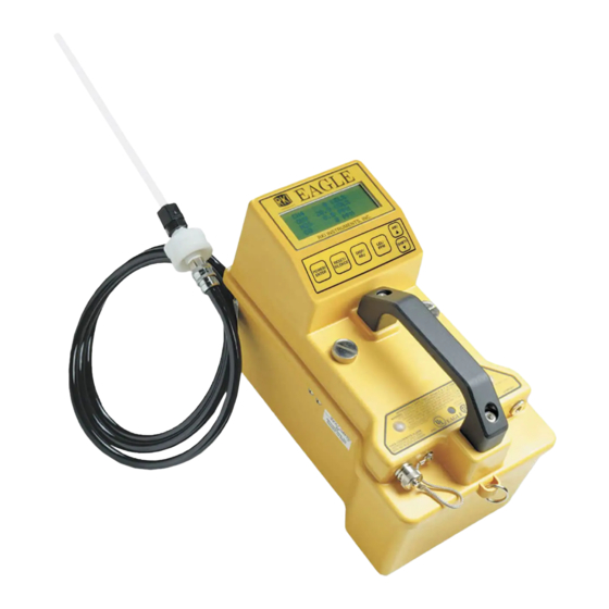
Introduction Overview The RKI Eagle is the most advanced portable gas detection system available. The Eagle is built for rugged reliability and ease of use and includes the latest innovations in gas detection technology: • Simultaneous detection of one to six gases. Standard target gases include combustible gas (% LEL and ppm), oxygen deficiency, carbon monoxide, and hydrogen sulfide. -
Page 9: Specifications
Specifications Table 1 lists physical and environmental specifications for the Eagle. Table 2 lists specifications for the Eagle’s standard sensors. Table 1: Eagle Specifications • Combustible gas Target Gases • Oxygen (O • Carbon monoxide (CO) • Hydrogen sulfide (H Case High-impact polycarbonate-polyester blend CSA/NTRL and UL classified intrinsically safe... - Page 10 Table 2: Standard Sensor Specifications Combustible Combustible Hydrogen Carbon Oxygen Sulfide Monoxide Gas (%LEL Gas (PPM Range 0 to 100% LEL Depends on 0 to 40% O 0 to 100 ppm 0 to 500 ppm target gas Alarm 1 10% LEL 5000 ppm 19.5% O 10.0 ppm...
-
Page 11: Description
Description Case The Eagle has a plastic case with a full-sized handle. The high-visibility case is shielded to reduce radio frequency and electromagnetic interference (RFI/EMI). The system is light-weight and balanced, which makes the Eagle easy to carry and use for extended periods. -
Page 12: Alarm Lights
Alarm Lights Two ultra-bright, red, light-emitting diodes (LEDs) provide visual indications for gas alarms and instrument malfunctions. They are mounted on the top rear of the case for greatest visibility. Battery Charger Connector The battery charger connector is at the top right rear of the case. The external battery charger connects to this connector to recharge nickel-cadmium (Ni-Cd) batteries. -
Page 13: Sensors
The standard probe includes a replaceable particle filter and hydrophobic filter disk that prevent particulates and water from entering the Eagle’s flow system. See “Replacing the Probe’s Particle Filter and Hydrophobic Filter Disk” on page 43 for instructions to replace the particle filter and hydrophobic filter disk. Sample Hose Standard Probe... -
Page 14: Circuit Boards
Oxygen Sensor The oxygen (O ) sensor is mounted face down in the sensor block to allow the sample flow to diffuse into the sensor. A multi-pin plug connects the O sensor to the CN2 socket on the analog PCB. The O sensor is an electrochemical cell, which reacts to the oxygen in the atmosphere and produces a voltage proportional to the oxygen concentration. -
Page 15: Operation
Operation The Eagle has four operating modes: normal operating mode, display mode, setup mode, and calibration mode. This section describes the Eagle in normal operating mode. It includes procedures to start up the Eagle, set various detection options for the combustible gas channel, and shut down the Eagle. NOTE: The screens illustrated in this section are intended as examples only. -
Page 16: Normal Operation
5. The Eagle does a self-diagnosis and alerts you if a malfunction occurs. E L F D I A N D S T O G O S T A N D > < O < > < > < > 6. -
Page 17: Monitoring Combustible Gas In The Ppm Range
Monitoring Combustible Gas in the PPM Range 1. Start the Eagle in the LEL range as described in “Starting Up the Eagle” on page 15. 2. Allow the combustibles sensor to stabilize (3 to 5 minutes). 3. Press the LEL/PPM button to switch the units from %LEL to ppm. 4. -
Page 18: Setting User Access
Table 4: Full Response Mode Conversion Factors (Methane Calibration) Target Gas LEL Factor PPM Factor Target Gas LEL Factor PPM Factor Ethyl Acrylate 2.45 0.69 Propane 1.50 0.63 Hexane 2.44 0.54 Styrene 2.94 0.53 Hydrogen 1.16 0.93 Toluene 2.16 0.48 Vinyl Acetate 1.48 0.77... -
Page 19: Alarms
Alarms Alarm Indications This section describes the Eagle’s audible and visual alarm indications for gas, over range, low flow, low battery, and sensor failure alarms. This section also describes how to reset gas alarms. The default alarm settings are listed in Table 2 on page 10. The alarm settings are user-adjustable as described in “Updating the Alarm Point Settings”... - Page 20 STEL Alarm (Toxics Only) If a toxic gas channel’s average gas reading for the past 15 minutes exceeds the STEL alarm setting: 2 0 . 9 S T E • STEL displays in the alarm field for that channel. • The channel’s display line flashes. •...
- Page 21 Low Flow Alarm If the Eagle’s sample system becomes restricted or blocked (for example plugged probe, fouled filter, pinched tubing): A I L L O W L O W L E V • The message FAIL LOW FLOW LEVEL replaces the normal screen. •...
-
Page 22: Resetting Gas Alarms
• The buzzer sounds a steady tone. • The alarms lights flash. If the sensor failed during start-up, the Eagle continues to normal operation and xxxxx replaces the failed sensor’s gas reading. If the sensor fails during normal operation and you want to continue monitoring for the remaining target gases, turn the Eagle off and on again. -
Page 23: Display Mode
Display Mode In display mode, you can: • set user and station IDs • view peak readings • view elapsed operating time • view TWA and STEL readings (toxic gases only) • view battery voltage Entering Display Mode Press the DISP/ADJ button to enter Display Mode. To scroll from one screen to the next press the DISP/ADJ button. -
Page 24: Peak Screen
Peak Screen The Peak screen displays the highest (lowest for O ) concentrations detected since the Eagle was turned on. Peak readings are stored in the Eagle’s memory until a higher level is detected, you reset them, or the Eagle is turned off. To reset the peak readings while using the Eagle, press and hold the RESET/SILENCE button while in the Peak screen until you hear a beep, then release it. -
Page 25: Setup Mode
Setup Mode In setup mode, you can: • update the battery type setting • update channel settings • update the combustible gas channel’s units of measure • update the alarm point settings • update the Eagle’s serial number • turn the lunch break function on or off •... -
Page 26: Updating The Battery Type Setting
Updating the Battery Type Setting This setting allows you to select between alkaline and Ni-Cd batteries. This setting helps the Eagle give low battery warning and low battery alarm indications at the appropriate times. This setting has no effect on battery charging. 1. - Page 27 NOTE: Select the HEX or *** setting for Methane Elimination (see “Appendix B: Methane Elimination” on page 49 for more information). 5. Press the POWER/ENTER button to save the new target gas label. 6. A screen displays that shows the fullscale PPM setting, which corresponds to 100% LEL, and the increments for the selected target gas label.
- Page 28 The maximum fullscale setting for the combustible gas channel is 50,000 ppm; the minimum setting is 1000 ppm. The default setting is 50,000 ppm. 2. Press the AIR/ and SHIFT/ buttons to display the desired fullscale setting (see Table 5), then press the POWER/ENTER button to save the setting. The cursor flashes.
- Page 29 Updating Oxygen Channel Settings This section describes how to update the target gas label, fullscale setting, and display increment setting for the oxygen channel. Updating the Target Gas Label 1. From the main menu, select the GAS COMBINATIONS menu option. >...
- Page 30 3. To exit the Gas Combinations menu, press the SHIFT/ button until the cursor is next to ESCAPE. 4. Press the POWER/ENTER button. The message SAVING DATA displays, then the main menu displays. Updating Toxic Channel Settings This section describes how to update the target gas label, set a custom gas label, and update the fullscale and display increment settings for a toxic gas channel.
-
Page 31: Updating The Combustible Gas Channel's Units Of Measure
Updating the Fullscale Setting 1. Press the SHIFT/ button to move the cursor to the second line, then press the POWER/ENTER button. The fullscale setting flashes. The maximum fullscale setting for a toxic gas channel is 1000 PPM; the minimum setting is 1.00 PPM. -
Page 32: Updating The Alarm Point Settings
Updating the Alarm Point Settings Each of the Eagle’s gas detection channels includes low and high gas alarms. The combustible gas channel also includes low and high alarms for PPM readings; the toxic gas channels also include STEL and TWA alarms. This screen allows you to update one or more alarm points. -
Page 33: Updating The Lunch Break Setting
1. From the main menu, select the SERIAL NO. menu option. 2. Press the AIR/ and SHIFT/ buttons to display the desired character, then press the POWER/ENTER button to save the character. The next character flashes. 3. Repeat step 2 to enter the remaining characters. The main menu displays after you enter the last character. -
Page 34: Updating The Alarm Silence Setting
Updating the Alarm Silence Setting NOTE: This feature works only when Alarm Latching is turned on. ON: Press the RESET/SILENCE button to silence the buzzer during an alarm. The LEDs continue to flash, and the display continues to show the level of alarm. When the gas concentration falls below the low alarm level, press the RESET/SILENCE button to turn off the LEDs and remove the ALM1 message. -
Page 35: Updating The Back Light Setting
1. From the main menu, select the AUTO CALIBRATION menu option. (To display the combustible gas channel in PPM, press the LEL/PPM button.) 2. Press and hold the SHIFT/ button, then press the DISP/ADJ button. The Auto Calibration screen for the combustible gas channel displays. B R A T I O N <... -
Page 36: Updating The Zero Follow Settings
1. From the main menu, select the AUTO FRESH AIR ADJ. menu option. 2. Press the AIR/ or SHIFT/ button to display the desired setting. 3. Press the POWER/ENTER button to enter the setting and return to the main menu. Updating the Zero Follow Settings The Zero Follow setting is not intended for customer setup. -
Page 37: Returning To Default Settings
Returning to Default Settings Each of the parameters in Setup mode has a default setting. The Eagle includes three different options for returning default settings: reset all default settings, reset the default alarm point settings only, and reset the default oxygen zero setting only. CAUTION: If you reset all default settings, any changes made in setup mode or normal operation, including calibration settings, will be lost. -
Page 38: Calibration
• An oxygen-free source, such as 100% nitrogen or CO in a nitrogen balance • A demand-flow regulator to provide adequate sample gas flow WARNING: RKI Instruments, Inc. recommends that you dedicate a regulator for use with chlorine (Cl ) gas and that you do not use that dedicated... -
Page 39: Calibrating The Eagle
Calibrating the Eagle NOTE: The following screens illustrate a four-gas Eagle with the data logging option and are intended as examples only. Your Eagle may display slightly different screens. > B R A T I O N C A L I B R A T I O N D A T N O R M The Eagle’s Calibration menu includes two methods of calibration: Auto Calibration... - Page 40 4. Use the AIR/ (increase) and SHIFT/ (decrease) buttons to set the correct combustible gas value. 5. Press the POWER/ENTER button to save the new setting. The Auto Calibration screen for the next channel displays. 6. Repeat steps 4 and 5 to set the correct values for the remaining channels and return to the Calibration Values screen.
- Page 41 2. Press the POWER/ENTER button to display the Single Calibration menu. > 3. Use the AIR/ or SHIFT/ button to place the cursor next to the channel to calibrate (in this example the combustible gas channel). 4. Press the POWER/ENTER button. The Single Calibration screen displays for the channel you selected.
-
Page 42: Maintenance
Maintenance Displaying the Battery Voltage Check the battery voltage periodically. Replace or recharge the batteries before the voltage drops to 4.5 V. WARNING: Take the Eagle to a non-hazardous location before replacing or recharging the batteries. To display the battery voltage: 1. -
Page 43: Replacing The Probe's Particle Filter And Hydrophobic Filter Disk
Replacing the Probe’s Particle Filter and Hydrophobic Filter Disk Inspect the probe’s internal components if you notice that the Eagle’s pump sounds bogged down or if an unexplained low flow alarm occurs. Replace the particle filter if it appears to be dirty. Replace the hydrophobic filter disk if it appears dirty or saturated with liquid. -
Page 44: Replacing Sensors
NOTE: If you have an Eagle that requires a super toxic probe, do not install the particle filter. 7. Place the new filter disk flat on top of the particle filter. Make sure it is centered over the particle filter (if installed). 8. - Page 45 5. Remove the two screws in the oval keeper plate, and remove the sensor from the sensor block. 6. Unplug the cable socket from the top of the sensor. Retain the oval keeper plate for use with the replacement sensor. 7.
- Page 46 3. Locate the toxic gas sensor you intend to replace. With the batteries closest to you, the sensor for Channel 3 is at the top right corner of the sensor block, and the sensor for Channel 4 is at the bottom right corner of the sensor block. Note the color of the leads extending from the sensor you intend to replace.
-
Page 47: Appendix A: Parts List
Appendix A: Parts List Table 6 lists part numbers for the Eagle’s replacement parts and accessories. Table 6: Parts List Part Number Description 07-7008RK O-ring for top case thumbscrews 07-7210RK O-ring for inlet fitting half of probe 07-7304RK O-ring for tube half of probe 13-0100RK Shoulder strap 13-1080RK... - Page 48 Table 6: Parts List (cont.) Part Number Description 65-0601RK Sensor, oxygen 65-2005RK Sensor, carbon monoxide 65-2035RK Sensor, hydrogen sulfide 71-0028RK Eagle Instruction Manual 80-0131RK-10 Probe, 10-inch hydrophobic (standard probe) 80-0132RK-10 Probe, 10-inch hydrophobic, super toxic (for Br , ClO , HBr, or HCL) 80-05XXRK Sample hose.
-
Page 49: Appendix B: Methane Elimination
Appendix B: Methane Elimination For applications where methane is an interfering gas, you can set the Eagle to eliminate most response to methane. The methane elimination switch is a standard feature on the circuit board inside the top of the Eagle’s case. An external switch is available as an option. -
Page 50: Monitoring Combustible Gases Other Than Hexane
Monitoring Combustible Gases Other Than Hexane Use Table 7 to determine the concentration of combustible gases other than hexane. This table is based on the Eagle being in methane elimination mode (methane elimination switch set to HEX ON) and calibrated to hexane. Multiply the display reading by the factor in the appropriate column. -
Page 51: Appendix C: Non-Standard Toxic Gas Sensors
Appendix C: Non-Standard Toxic Gas Sensors Appendix C describes the Eagle’s non-standard, electrochemical toxic gas sensors (sensors other than CO or H S). This appendix also describes calibrating and replacing non-standard toxic gas sensors. Specifications Table 8 lists specifications for the non-standard toxic gas sensors. The alarm settings are user-adjustable (see “Updating the Alarm Point Settings”... -
Page 52: Hose And Probe
Table 8: Non-Standard Toxic Gas Sensors Specifications STEL Target Gas Range Alarm 1 Alarm 2 Alarm Alarm Ozone** 0 to 1.00 ppm 0.10 ppm 0.30 ppm 0.08 ppm 0.10 ppm Phosphine 0 to 1.00 ppm 0.10 ppm 0.30 ppm 0.30 ppm 1.00 ppm Silane 0 to 15.0 ppm... -
Page 53: Calibrating Non-Standard Toxic Gas Sensors
POWER/ENTER button. 3. Screw the regulator to the appropriate calibration cylinder. WARNING: RKI Instruments, Inc. recommends that you dedicate a regulator for use with chlorine (Cl ) gas and that you do not use that dedicated regulator for any other gases, particularly hydrogen sulfide (H 4. -
Page 54: Replacing Non-Standard Toxic Gas Sensors
• The toxic gas reading cannot be set to zero by the Demand Zero command or zero potentiometer. NOTE: RKI Instruments, Inc. recommends that you return the Eagle for replacement of the non-standard toxic gas sensor. The following procedure is provided to allow you to replace the sensor if necessary. -
Page 55: Parts List
the case and lay it aside. 3. In the front half of the bottom case, locate the sensor you want to replace. The sensor with wires connected to EC3 on the analog PCB displays its reading on the third line of the screen. The sensor connected to EC4 on the analog PCB displays its reading on the fourth line of the screen. - Page 56 Table 9: Parts List: Non-Standard Toxic Gas Sensors Part Number Description 81-1054RK Regulator, demand-flow type, for all gases 81-0154RK-H2S is not appropriate for in 58- and 103-liter calibration cylinders (cylinders with internal threads) 81-1054RK-H2S Regulator, demand-flow type, for CO, CO S, N , NO, NO , PH...
-
Page 57: Appendix D: Carbon Dioxide Sensors
Appendix D: Carbon Dioxide Sensors Appendix D describes the Eagle’s infrared carbon dioxide (CO ) sensors. It also describes calibrating and replacing CO sensors. Specifications Table 10 lists specifications for the carbon dioxide sensors. The alarm settings are user-adjustable (see “Updating the Alarm Point Settings” on page 32). Table 10: Carbon Dioxide Sensor Specifications Range Alarm 1... -
Page 58: Normal Operation Of Carbon Dioxide Sensors
CAUTION: Do not connect the probe to the scrubber during normal operation or when setting the span reading during calibration. Normal Operation of Carbon Dioxide Sensors Carbon dioxide is a background gas in fresh air. Table 11 indicates typical fresh air readings for each of the Eagle’s carbon dioxide sensors. -
Page 59: Calibrating Carbon Dioxide Sensors
Calibrating Carbon Dioxide Sensors Recommended calibration frequency for carbon dioxide sensors is once every 3 months. Enter Calibration mode and calibrate carbon dioxide sensors as described in the Calibration section of this manual. Use the Auto Calibration method if a calibration cylinder is available that includes all target gases for your Eagle. -
Page 60: Replacing Carbon Dioxide Sensors
OPERATION menu option, then press the POWER/ENTER button to return to the normal screen. Replacing Carbon Dioxide Sensors Return the Eagle to RKI Instruments, Inc. for replacement of the carbon dioxide sensor when: • The carbon dioxide channel cannot be calibrated correctly. -
Page 61: Parts List
Parts List Table 12 lists part numbers for replacement parts and accessories of the Eagle’s carbon dioxide sensors. Table 12: Parts List: Carbon Dioxide Sensors Part Number Description 33-6010RK-01 Scrubber, carbon dioxide 81-0070RK-03 Calibration cylinder, 103-liter (2000 ppm CO 81-0071RK-03 Calibration cylinder, 103-liter (5000 ppm CO 81-0072RK-03 Calibration cylinder, 103-liter (2.5% CO... -
Page 62: Appendix E: Infrared Methane Sensors
Appendix E: Infrared Methane Sensors This appendix describes the Eagle’s infrared methane sensors. This appendix also describes calibrating and replacing the infrared methane sensors. Target Gases The infrared methane sensors are setup for and factory-calibrated to methane. The infrared methane sensor also responds to the following combustible gases: ethane, hexane, IPA, isobutane, MEK, propane, toluene. -
Page 63: Calibrating Infrared Methane Sensors
Table 14: Sensor Configuration for Infrared Methane Sensors (0 to 100% Volume) Channel Sensor Analog PCB Socket Infrared methane (0 to 100% Vol. CH Oxygen Toxic gas or infrared carbon dioxide EC1, EC2, or EC3 Calibrating Infrared Methane Sensors Recommended calibration frequency for the infrared methane sensor is once every 3 months. -
Page 64: Replacing Infrared Methane Sensors
Replacing Infrared Methane Sensors Return the Eagle to RKI Instruments, Inc. for replacement of the infrared methane sensor when: • The infrared methane channel cannot be calibrated correctly. • The infrared methane reading cannot be set to zero by the Demand Zero command. -
Page 65: Appendix F: Infrared Hc Sensor
Appendix F: Infrared Hydrocarbon Sensor This appendix describes the Eagle’s infrared hydrocarbon (HC) sensor. This appendix also describes calibrating and replacing the infrared HC sensor. Target Gases The infrared HC sensor is a general hydrocarbon sensor and is factory-calibrated to isobutane. -
Page 66: Calibrating The Infrared Hc Sensor
5. 6. Continue with the normal calibration procedure. Replacing the Infrared HC Sensor Return the Eagle to RKI Instruments, Inc. for replacement of the infrared HC sensor when: • The infrared HC channel cannot be calibrated correctly. -
Page 67: Parts List
Parts List Table 18 lists part numbers for replacement parts and accessories of the Eagle’s infrared HC sensor. Table 18: Parts List: Infrared HC Sensors Part Number Description 06-1248RK-03 Tubing, 3/16” x 5/16”, polyurethane, 3 foot length, for calibration kit 81-0018RK Calibration cylinder, 50% LEL isobutane in air, 17 liter steel 81-0018RK-01... -
Page 68: Appendix G: Eagle Tank Tester Model
Appendix G: Eagle Tank Tester Model The Eagle Tank Tester model is intended for checking tanks or vessels that may contain residual hydrocarbon vapors or water or may have been purged of oxygen. You can also use this model as a standard Eagle gas monitor by connecting the standard hose and probe and updating the oxygen alarms to the default settings. -
Page 69: Alarms
Alarms The Eagle Tank Tester model has two alarms for oxygen. They are factory-set at 5.0% by volume (increasing) and 19.5% by volume (decreasing). The increasing alarm is used to monitor a purged vessel to alert you to a rising oxygen condition. -
Page 70: Appendix H: Five-Gas And Six-Gas Models
Appendix H: Five-Gas and Six-Gas Models Overview The standard Eagle gas monitor includes one to four channels and displays gas readings for all channels simultaneously. Some Eagle models include five or six channels; however, the Eagle is only capable of displaying gas readings for four of the channels at any one time. -
Page 71: Alarms
Alarms If the Eagle recognizes an alarm condition for a non-displayed channel, the cursor flashes and the standard audible and visual alarms initiate. • If the alarm occurs for a channel before the top displayed channel, the cursor in the first line flashes. Press the AIR/ button to display the channel in alarm. -
Page 72: Appendix I: Eagle Transformer Gas Tester
Appendix I: Eagle Transformer Gas Tester Model This Eagle Transformer Gas Tester Model is specially set up for electrical transformer gas testing. Large electrical transformers are filled with oil which surrounds the transformer coils, and they have an inert gas head space above the oil. When a transformer begins to fail, electrical arcing between the conductors of the coils can cause flammable gases to form in the head space. -
Page 73: Alarms
Alarms All the gas alarms on the Transformer Gas Tester are set to OFF. Part List Table 20: Parts List: Eagle Tank Tester Model Part Number Description 80-0405RK Dilution fitting (1:1) 81-1126RK Sample bag, 9” x 12”, tedlar Eagle Instruction Manual Appendix I: Eagle Transformer Gas Tester Model •... -
Page 74: Appendix J: Eagle Transformer Gas Tester Model Trb
Appendix J: Eagle Transformer Gas Tester Model TRB The TRB Eagle is specially set up for electrical transformer gas testing. Large electrical transformers are filled with oil which surrounds the transformer coils and they have an inert gas head space above the oil. When a transformer begins to fail, electrical arcing between the coil conductors can cause flammable gases to form in the head space. -
Page 75: Parts List
Calibration Because of the internal construction of the TRB Eagle, it is not necessary to use a gas bag to calibrate the unit. A demand flow regulator may be used to calibrate it. Follow the instructions in “Calibration” on page 38 to calibrate the unit. Alarms All of the gas alarms on the TRB Eagle are set to OFF.
Need help?
Do you have a question about the Eagle Series and is the answer not in the manual?
Questions and answers