Table of Contents
Advertisement
RIKEN
PORTABLE COMBINATION GAS DETECTOR
MODEL RX−516
RX−517
Precaution in operation
・After reading this manual well, start to operate this instrument.
・Keep this manual where to carry out easily
・When take out this manual by use of construction work, be sure to put it
where it was.
・Do not use this instrument for no other than given purpose.
・When operate this instrument without using this manual or repair it by use of
no other parts than the genuine one, the safety and quality of products could
not be guaranteed. When any accident should take place by those irregular
method, we cannot assume the responsibility for it.
All manuals and user guides at all-guides.com
OPERATION MANUAL
MARINE USE
2-7-6 Azusawa Itabashi-ku Tokyo, 174-8744 Japan
Phone :
Tokyo
(03) 3966-1113
Telex
: 272 2638 RKNFNE
Fax
: (03) 3558 9110 GⅢ
E-Mail : intodept@rikenkeiki.co.jp
PT0E‑0730
Advertisement
Table of Contents

Related Manuals for RKI Instruments RIKEN RX-516


Summary of Contents for RKI Instruments RIKEN RX-516
- Page 1 PT0E‑0730 All manuals and user guides at all-guides.com RIKEN PORTABLE COMBINATION GAS DETECTOR MODEL RX−516 RX−517 OPERATION MANUAL MARINE USE Precaution in operation ...
- Page 2 PT0E‑0730 All manuals and user guides at all-guides.com In the beginning It is of our great pleasure to purchase Riken portable combination gas detector model RX-516/RX-517 this time. This instrument is an explosion-proof type portable gas detector which is designed to measure the presence of the following gas at crude oil tankers shown below.
-
Page 3: Table Of Contents
PT0E‑0730 All manuals and user guides at all-guides.com C O N T E N T S 1.Caution in operation ・・・・・・・・・・・・・・・・・・・・・・・・・・・・・ 3 2.Name of each part・・・・・・・・・・・・・・・・・・・・・・・・・・・・・・・ 4 3.Operation・・・・・・・・・・・・・・・・・・・・・・・・・・・・・・・・・・・ 8 3−1.Check item before operation・・・・・・・・・・・・・・・・・・・・・ 8 3−2.Preparation・・・・・・・・・・・・・・・・・・・・・・・・・・・・・・ 8 3−3.Start‑up and end‑up・・・・・・・・・・・・・・・・・・・・・・・・・・ 9 3−4.Flow monitor check・・・・・・・・・・・・・・・・・・・・・・・・・・ 10 3−5.Zero point adjustment・・・・・・・・・・・・・・・・・・・・・・・・ 10 3−6.Operational procedure・・・・・・・・・・・・・・・・・・・・・・・・ 12 3−7.Peak value mode・・・・・・・・・・・・・・・・・・・・・・・・・・・・ 13 3−8.Power pump ON/OFF・・・・・・・・・・・・・・・・・・・・・・・・・・・ 13 3−9.Operation finished・・・・・・・・・・・・・・・・・・・・・・・・・・ 14 3−10. Practical application・・・・・・・・・・・・・・・・・・・・・・・・ 15 4.Alarm・・・・・・・・・・・・・・・・・・・・・・・・・・・・・・・・・・・・ 16 4−1.Alarm display・・・・・・・・・・・・・・・・・・・・・・・・・・・・・ 16 4−2.Alarm buzzer & lamp・・・・・・・・・・・・・・・・・・・・・・・・・ 16 4−3.Trouble display・・・・・・・・・・・・・・・・・・・・・・・・・・・・ 17 5. E ach function・・・・・・・・・・・・・・・・・・・・・・・・・・・・・・・・・ 19 5−1.Operation mode control・・・・・・・・・・・・・・・・・・・・・・・・ 19 ... -
Page 4: 1.Caution In Operation
PT0E‑0730 All manuals and user guides at all-guides.com 1.Caution in operation To maintain the function for safety, follow the following instruction. Warning ・Do not modify nor change the circuit and structure etc. When modify or change, it could not maintain the function. ・This is explosion‑proof product. Battery has to be replaced in non‑hazardous zone. The battery replacement in hazardous zone shall be out of the scope for explosion‑proof product. ・This is explosion proof. Be sure to operate with carrying case on. ・Do not measure in the environment of oxidant gas presence. When measure, it may shorten the sensor life. ... -
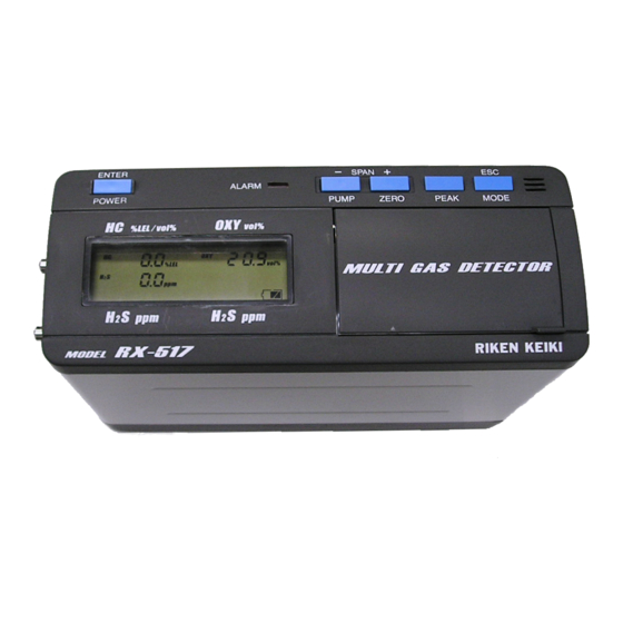
Page 5: 2.Name Of Each Part
PT0E‑0730 All manuals and user guides at all-guides.com 2 Name of each part . ⑥ ③ ④ ⑤ ② ① GAS OUT H2S Low・HC・O2 GAS IN ⑦ ⑧ GAS OUT H2S high ①POWER/ENTER SW This is used for power ON/OFF and entering the figure. ②PUMP/− SW This is used when make the pump ON/OFF and deverse the figure. ③ZERO/+SW This is used when make zero adjustment and increase the figure. ④PEAK SW This is used when to let the peak displayed. ... - Page 6 PT0E‑0730 All manuals and user guides at all-guides.com 《Display of RX‑516/517》 Hydro carbon 「 HC」 Oxygen「OXY」 RX‑517 RX‑516/RX‑517 Hydrogen sulfide(High) 「H2S」 Hydrogen sulfide(Low) 「H2S」 *Caution ・For HC, when it goes over 100%LEL, it shall be changed to vol% automatically. 《RX‑517 case》 ・ H2S can be changed over by H2S gas range mode cock. (H2S High ⇔ H2S Low) ...
- Page 7 PT0E‑0730 All manuals and user guides at all-guides.com 【Standard accessories】 ①Carrying case with shoulder strap ②Filter tube with flow monitor and junction tube ③Gas sampling probe ④Gas sampling hose ...
- Page 8 PT0E‑0730 All manuals and user guides at all-guides.com 【Optional accessories】 ①Gas sampling hose 30m with plummet ②Gas sampling hose 30m with float type sampling head ③Gas sampling bag 1L for LEL and VOL and calibration gas cylinder ...
-
Page 9: 3.Operation
PT0E‑0730 All manuals and user guides at all-guides.com 3.Operation 3−1.Check item before operation RX‑516 or 517 instrument: ・Check that there is no damage for display unit etc. Filter tube with flow monitor: ・Check the dirt of inside cotton filter. When it gets dirt, replace the cotton filter with new one. ・When water drops remain, wipe it out and change it with new one. ・Check that these is no crack or damage. ・Check that these is no loose mount on the nipple. Gas sampling hose: ・Check that there is no crack, creek or twist on the instrument. 3−2.Preparation (1) Dry batteries are put into instrument. (2) Put carrying case on to instrument. (3) Connect the ①instrument(Gas inlet)+②Filter tube with flow monitor+③Sampling hose respectively. ① ③ ② For gas sampling, 3 kinds tip formation are available and change it according to he measuring environment. ... -
Page 10: 3−3.Start-Up And End-Up
PT0E‑0730 All manuals and user guides at all-guides.com 3−3.Start‑up and end‑up When press power switch for 3 sec, the power gets on and this shall start up sequencing the program of the voltage check, filter connection check and sensor connection check respectively. Press power switch for 3 sec. Date/time display PREPARATION Stand‑by PROBE OK? Accessory connection check ・Press ENTER key FILTER OK? (Display word atternately) ENTER key SENSOR CHECK 【Sensor trouble】 【Sensor normal】 FAIL SENSOR SENSOR OK WARM UP 30 Warm up WARM UP 30 STAND BY Operation ready STAND BY Operation mode Press POWER SW for 3 sec Trouble sensor shall show …… . Power off ... -
Page 11: 3−4.Flow Monitor Check
PT0E‑0730 All manuals and user guides at all-guides.com 3−4.Flow monitor check When the power gets ON, the pump shall start operation check that suction works properly by filter tube with flow monitor. Float At normal sucking(Can see float) Not sucking(Can not see float) 3−5.Zero point adjustment Zero point calibration for this instrument shall be done HC, O2(Oxygen), H2S(Hydrogen sulfide). Caution When make zero adjustment, proceed to do it after having fresh air sucked into instrument for over 1 min. When make zero adjustment through the suction of gas present atmosphere, ... - Page 12 PT0E‑0730 All manuals and user guides at all-guides.com <FLOW CHART OF ZERO POINT ADJ> ZERO MODE DISPLAY ZERO key ・Press ZERO key for 3 sec. HOLD KEY ・When press ENTER key, HC, O2, H2S zero adj shall start. ESC key FRESH AIR? Move to zero adj ENTER key for CO2 adj ESC key ADJ ZERO OK ・Calibration 《Zero set OK》 《Zero adj fails》 ZERO SET OK FAIL ZERO Press for 5 sec and move to the display. HC fails All are OK *Note ・To cancel previous operation, press ESC key. But can not cancel after press ENTER key. 《RX‑517 case》 ・For zero adjustment of H2S high, proceed to make zero adjustment by changing to the ...
-
Page 13: 3−6.Operational Procedure
PT0E‑0730 All manuals and user guides at all-guides.com 3−6 .Operational procedure Approach the sampling hose to the sampling site for measurement and leave sampling gas sucked. ・Take care that any twist on the sampling hose can not be made. ・Stop sampling hose at the point of measurement. ・From the hose length consider the delay time and read out the reading after the reading gets stable. Danger ・Oxygen depletion air etc may be exhausted from gas outlet. Do not breathe in there absolutely. ・High density gas over (LEL) may be exhausted. Do not approach fire there absolutely. Warning ・In the place where environment temp is remarkably changed, there may be the case that ... -
Page 14: 3−7.Peak Value Mode
PT0E‑0730 All manuals and user guides at all-guides.com 3−7.Peak SW value mode When press PEAK SW during operation, the peak valve from power on to the current point (HC, H2S = MAX, O2=MIN) shall be shown. 【RX‑516/517】 Peak mode Operation mode PEAK SW P E A K H2S change over 【RX‑517】 H2S high display Peak display PEAK key P E A K *Note 《RX‑517 case》 ・In the H2S high display, the peak value of H2S is displayed. ・When changed from peak display, it changes to the operation display. When hold and press ESC key for 3 sec during the peak value display, the peak value shall be cleared. Operation mode Peak mode ESC SW P E A K *注記 《RX‑517 case》 ... -
Page 15: 3−9.Operation Finished
PT0E‑0730 All manuals and user guides at all-guides.com Operation mode ・Press pump key for 3 sec. PUMP key HOLD KEY ・Pump work will be off. PUMP OFF PUMP key ・Press pump key for 3 sec. HOLD KEY PUMP ON ・Pump work will be on. Hold and press for 5 sec and back to the operation display. 3−9.Operation finished (1)Treatment after operation Wind up sampling hose so treat it can not be twisted and bent. Supply fresh air in the condition of sampling hose connected and make air‑cleaning until the reading gets to zero nearly. When use the floating gas sampling head or 30m sampling hose (30m: optical acc.), be sure to make air‑cleaning for 5 minutes before use. (2)Power OFF When hold and press power SW for about 5 sec, the buzzer sounds 8 times and the power will be off. Caution ... -
Page 16: 3−10. Practical Application
PT0E‑0730 All manuals and user guides at all-guides.com 3−10.Practical application (1) Tank inside of crude oil tanker By use of sampling hose with plummet, it is available to monitor the gas density in the tank. 《Sample in crude oil tanker》 COMBINATION GAS COMBINATION GAS DETECTOR DETECTOR AIR VENT HEAD AIR VENT HEAD SAMPRING SAMPRING PIPE PIPE GAS SAMPRING PIPE GAS SAMPRING PIPE ... -
Page 17: 4.Alarm
PT0E‑0730 All manuals and user guides at all-guides.com 《Interference measures in inert gas》 In the component of inert gas, a lot of interference gas may be present. When it should be present so much to affect the measurement, it shall be required to mount the interference removal filter. 4.Alarm 4−1.Alarm display ①At 1 alarm, the figure will blink and Warring will blink. ②At 2 alarm, the figure will blink and Alarm will blink. ③At over alarm, the figure will blink and Over will blink. 《1 alarm》 Alarm≧1 alarm set(HC、H S) Alarm≦1 alarm set(O ) W A R N I N G 【WARNING display, Intermittent LED, Blink】 《2 alarm》 Alarm≧2 alarm set ... -
Page 18: 4−3.Trouble Display
PT0E‑0730 All manuals and user guides at all-guides.com 4−3.Trouble display (1)Low flow alarm ・When low flow trouble triggers, LOW FLOW is displayed and pump stops working. ・Buzzer sounds continuously. ・After checking the cause, reset low flow alarm by ESC key. The pump will re‑start and return to the operation display. Pump ON Pump OFF LOW FLOW ESC key Caution When low float trouble took place, be sure to check the cause to make low flow. Especially when suck water, it will be the cause for trouble. After checking the condition of probe filter tube, re‑start the pump by ESC key. (When press ESC and re‑start in the water remaining condition, there will be the case of water intrusion into instrument. For low flow trouble, it shall be cautioned that no error display will be the setting mode. ... - Page 19 PT0E‑0730 All manuals and user guides at all-guides.com (3)System trouble alarm ・When the program is troubled, SYSTEM FAIL will be shown. ・Buzzer will sound continuously. ・After SYSTEM FAIL is shown, it does not accept other than Power off . SYSTEM FAIL S A V E Power off available only by power SW (4)Sensor trouble alarm ・When sensor is troubled, FAIL SENSOR is displayed and the measuring gas for the troubled will be shown. (Sensor for trouble detected at start‑up time shall be shown.) ・Buzzer will sound continuously. ・After showing FAIL SENSOR , it does not accept other than Power off . F A I L S E N S O R POWER off available only by power SW ...
-
Page 20: 5.Each Function
PT0E‑0730 All manuals and user guides at all-guides.com 5.Each function 5−1.Operation mode control Operation mode ・Press MODE key for 3 sec. MODE key HOLD KEY Displayed in the following order ① 1 alarm ①1 alarm display ② 2 alarm MODE key ③ Data display ④ Data logger remaining W A R N I N G − PEAK key + ・ 『+』or『−』 key: When press it, To alarm setting − ... -
Page 21: 5−1−1.Alarm Setting
PT0E‑0730 All manuals and user guides at all-guides.com 5−1−1.Alarm setting alarm display ・Input the password【3002】. ・When press『+』or『−』, the number will be changed. W A R N I N G ・Fix the number by ENTER key and move to next digit. PEAK key ・After fixing the last digit, move to alarm setting (When make the password error, it will show ERROR . Press ESC key.) ・First, 1 alarm point shall be shown on the M ‐ P A S S W O R D display. ・Change 『+』or『−』key and confirm it by ENTER key pressing ENTER key. ・When press ESC key, the setting shall be void and first alarm point shall be shown. ・Then 2 alarm point of CH4 shall be shown on ESC key W A R N I N G the display. ENTER key ・When change by『+』or『−』key, confirm it by ENTER key. ・When press the setting by ESC key, go back to ... -
Page 22: 5−1−2.Date/Time Setting
PT0E‑0730 All manuals and user guides at all-guides.com 5 −1−2.Date/time setting Date/time display D A T E / T I M E ・First, set the year. PEAK key ・The set number shall blink. ・The change of number is set by 『+』 or『−』key. ・ Press ENTER key and the number is D A T E / T I M E ESC key entered. ・When press ESC key, the set work stops in the way and go back to the date ENTER key /time display. Year Month Set each in this Day turn. Hour Minute ・ After finish the minute, press ENTER key. ... -
Page 23: 5−3.Data Logger
PT0E‑0730 All manuals and user guides at all-guides.com 5−3.Data logger Data logger function has following 5 kinds. (1)Interval trend The change of measuring gas shall be recorded until the power on into off. Recording time can 100 times data. When it is over 100 times, the old data shall be deleted and record the new data by up‑dating. ※But when exceed the max recording time within 100 times, the old data shall be deleted. The max record time for interval time shall be as follows. Interval time 10 sec 30 sec 1 min 3 min 5 min 10 min Max record time 10 H 30 H 60 H 180 H 300 H 600 H ※Standard interval time shall be 30 sec. The interval time can be adjusted by Data Management Program (Option) . (2)Alarm trend This record the alarm trigger and the change of measuring valve for 30 minutes (Total: 1 hour) to fro and back of alarm triggering point. ... -
Page 24: 6.Maintenance Check
PT0E‑0730 All manuals and user guides at all-guides.com 6.Maintenance check For this correct operation, follow to the following procedure. As this is safety instrument. Be sure to make the regular maintenance. If any trouble should take place, contact RIKEN KEIKI or nearest agent. 6−1.Battery replacement Warning ・ For battery replacement, make it non‑hazardous area by all means after turning off the power. ・ Be sure to change the battery with the genuine ones. When replace the batteries, replace all four pcs with new ones. ① Check that the power if off. But when the power is on, make off the power first by use of POWER/ENTER key. Battery cover ... -
Page 25: 6−2.Gas Calibration (Span Adjustment)
PT0E‑0730 All manuals and user guides at all-guides.com 6−2.Gas calibration (Span adjustment) ・ Hold and pressing ZERO and PUMP key similtaneously in the operation mode. ZERO key ・ First, CH4 display shall be shown. ・ When press EMTER key, HC gas PUMP key calibration shall start. HOLD KEY ・ When press 『+』key, it shall change to gas calibration of 「OXY」→「H2S」. ESC key ・ When pressing ESC key, it shall return to + SPAN GAS HC Operation display . ・ This shall display gas name, gas density and unit. ENTER key ... - Page 26 PT0E‑0730 All manuals and user guides at all-guides.com Danger ・Compressed cylinder gas is used for gas calibration and take care at handling. ・At calibration by combustible gas, do not approach it to the fire. ・Exhaust the remaining gas in the sampling gas appropriately. Caution Before gas calibration, be sure to make zero adjustment. 《Handling of sampling bag and canned gas》 ① Sample the cal gas into sampling bag from canned gas. Canned gas Sampling bag ② Sampling bag with cal gas in shall be used by putting to gas in side at gas calibration. Danger Do not make gas calibration by use of lighter gas. By the ingredient in the lighter ...
- Page 27 PT0E‑0730 All manuals and user guides at all-guides.com 《Cal gas make‑up by H2S gas checker CK‑82》 ① Take out 1 pce. ampoule from accessory ampoule pack. ② Check that the rubber caps are fixed in the cover of container. ③ Open the cover of container and deflate the air by squeezing the pressure adj bag. ④ Put up the ampoule crusher know and put the ampoule into ampoule crusher inside of the cover shown below. When the ampoule is put in reversely, the ampoule may be crushed. Ampoule crusher knob Crush the ampoule by pressing the ampoule crusher knob Ampoule ⑤ After the ampoule is put in, close the cover. ⑥ Check that the rubber caps are put on the top cover. ⑦ After checking that the cover is closed, put in the ampoule crusher knob and crush the inside ampoule. ⑧ ...
-
Page 28: 6−3.Filter Replacement
PT0E‑0730 All manuals and user guides at all-guides.com 6−3.Filter replacement For filter (cotton) inside of filter with flow monitor, check it before use and when it gets dirty, replace it. (1)Turn the knurling part in depth for filter tube with flow monitor and open the inside. (2)Remove the cotton of it by tweezers etc. (3)Put the cotton filter uniformly on even base inside of filter tube and return back the filter tube in reverse procedure. Knurling cap Caution ・ Do not put cotton filter too much inside. ・ When suction flow is too much, it will be difficult to monitor accurately. *Note ・The cotton filter replacement should be make once in a month. 6−4.Sensor replacement When the following phenomenon took place, it will be the life end of sensor. (1) It can not calibrate. ... -
Page 29: 6−6.The Replacement Of Parts
PT0E‑0730 All manuals and user guides at all-guides.com 6−6.The replacement of parts The following parts have a life and each, regular replacement shall be recommended. When replace, contact RIKEN KEIKI or nearest agent. 《Recommended consumable parts list for replacement》 No. Name Check Replacement frequency frequency (Year) 1 Sensor pack 6 months 1 2 Internal filter 6 months 1 3 Pump 6 months 1 4 Interference removal filter 12 months 1 5 Hydrophobic filter ... -
Page 30: 6−7.Storage Or Treatment Not To Use For A Long Period
PT0E‑0730 All manuals and user guides at all-guides.com 6−7.Storage or treatment not to use for a long period The instrument shall be kept in the following condition. Temp :10〜30℃ Humidity :30〜80%RH Environment:Place free from gas and solvent vapours. Store the instrument in the box kept in originally. When the storage box was lost, store it in vinyl pack etc. 7.Scrap of products When dispose the waste, follow the regional low etc locally and do it in the same category wite the industrial waste through the appropriate procedure any harmful materials are not used except oxygen sensor and H2S sensor. For O2 sensor and H2S sensor waste, contact RIKEN KEIKI or nearest agent. 29... -
Page 31: 8.Trouble Shooting
PT0E‑0730 All manuals and user guides at all-guides.com 8.Trouble shooting This trouble shooting does not mention all the trouble causes. The following is mentioned briefly by picking up the point to help survey of trouble cause in high frequency. Phenomenon Cause Treatment SYSTEM FAIL ・Excess noise effects etc. ・ Re‑start up and check status. Request to manufacture. FAIL SENSOR ・Sensor trouble ・Check connect status and contact manufacture. ・Did excess shock etc by dropping, ・Check connect status and contact manufacture. crushing. FAIL FLOW ・Water, oil are soaked. ・Check whether any damage, suction marks of water, oil etc shall be found on sampling hose and filter ... -
Page 32: 9.Definition Of Words
PT0E‑0730 All manuals and user guides at all-guides.com 9.Definition of words Vol% Gas density is expressed by the unit of a part. ppm Gas density is expressed by the unit of a part per. 10,000ppm=1vol% %LEL Suppose to put the Lower Explosive Limit as 100 and at that time, combustible gas density is expressed by the unit of a part per hundred. Iso‑butane:100%LEL=1.8vol% N‑hexane :100%LEL=1.2vol% Calibration By use of calibration gas etc, it is to adjust the reading, display value or set value to the true valued. PEAK value MAX or MIN value in a period. ALARM preset value This is an alarm preset point value to give alarm when it comes to this alarm point. Maintenance check This is a work to maintain the required function and condition to perform. ... -
Page 33: 10.Specifications
PT0E‑0730 All manuals and user guides at all-guides.com 10.Specifications Refer to the specifications for separate catalog overleaf. Model RX-516 (HC/O2/H2S 0-100.0ppm) , RX-517 (HC/O2/H2S 0-100.0ppm & 0-1000ppm) Gas detected Iso-butane (HC) Oxygen (O2) Hydrogen sulfide (H2S) Detection NDIR(Non-Dispersive Galvanic cell Electro-chemical cell principle infrared) <LOW> Detection range 0-100%LEL (0.5%LEL) 0-25.0vol% <HIGH> 0-100.0ppm (digit) 2-100vol% (0.5vol%) (0.1vol%) 0-1,000ppm (1ppm) (0.5ppm) Operating Temp. & -10 〜 +50℃, below 90%RH (non-condensing) Humidity ... -
Page 34: 11.Detection Principle
PT0E‑0730 All manuals and user guides at all-guides.com 11.Detection principle NDIR method (Non‑Dispersive Infrared) 11−1 . The model is based on NDIR method (Non‑Dispersive Infrared) and this structure is shown below. The infrared beam emitted from the light source passes through the measuring cell, and optical band pass filter which can pass the absorption wave of measuring gas and attains to the infrared sensor. The amount of infrared attaining to the infrared sensor through the measuring cell and will decrease according to its density. The variable amount of infrared is measured by the infrared sensor and it is displayed as gas concentration. Then, there is no sensitivity against CO etc which have the different absorption wave from the measuring gas. Then there is no sensitivity against N2 and H2 etc which cannot absorb infrared. As compared with the conventional catalytic combustion method, there is no poisoning material to be absorbed and almost no sensitivity drop on this detection principle. Band path Light source Measuring cell Detector filter Out GALVANIC CELL method ... -
Page 35: 11−3.Electro-Chemical Cell Method
PT0E‑0730 All manuals and user guides at all-guides.com 11−3.ELECTRO‑CHEMICAL CELL method This gas detector applies an electrochemical sensor. The sample gas is electrolyzed by the electrolyzed cell added with specific electric potential (bias voltage) and detected from the electrolyzed current generated at that time. The electrochemical sensor is designed to keep the interface between electrode and electrolyte at a constant potential (Bias voltage) and is the method to electrolyze gas directly. Then as the gas has the bias voltage generating its own electrolization (Rrdox reaction) the bias voltage of sensor is determined by the redox potential. 32 ポテンショスタット回路 PS circuit 気体透過膜 GPF R(抵抗) Gas in RE 参照電極 電解液... - Page 36 All manuals and user guides at all-guides.com...
Need help?
Do you have a question about the RIKEN RX-516 and is the answer not in the manual?
Questions and answers
hello i am a deck cadet and i need to learn these equipment. what is the main difference between gx 8000 and rx 516 while we are using at crude oil tankers. when do we have to use rx516 and when do we have to use gx8000. for example if the tank is filled up with ig which equipment do we have to use and why, what is the main difference of working principle of these 2 gas meters.