
Related Manuals for RKI Instruments GasWatch 2


Summary of Contents for RKI Instruments GasWatch 2
- Page 1 GasWatch 2 Operator’s Manual Part Number: 71-0065RK Revision: F Released: 2/2/11 www.rkiinstruments.com...
- Page 2 Typical calibration frequencies for most applications are between 1 and 3 months, but can be required more often or less often based on your usage. GasWatch 2 Operator’s Manual...
- Page 3 Warranty RKI Instruments, Inc. warrants the GasWatch 2 sold by us to be free from defects in materials, workmanship, and performance for a period of two years from the date of shipment from RKI Instruments, Inc. This includes the instrument and the original sensors. Replacement parts are warranted for 1 year from the date of their shipment from RKI Instruments, Inc.
-
Page 4: Table Of Contents
Turning Off the GasWatch 2 ........ - Page 5 WARNING: Understand manual before operating. Substitution of components may impair intrinsic safety. To prevent ignition of a hazardous atmosphere, batteries must only be changed in an area known to be nonhazardous. Not tested in oxygen enriched atmospheres (above 21%). GasWatch 2 Operator’s Manual Table of Contents...
-
Page 6: Introduction
The GasWatch 2 is even small enough to be worn comfortably on the wrist like a watch. The GasWatch 2 offers a full range of features, including: •... -
Page 7: Specifications
Specifications Table 1: GasWatch 2 Specifications GW-2C GW-2H GW-2X Target Gas Carbon Monoxide Hydrogen Sulfide Oxygen (CO) Detection Range 0 to 500 ppm 0 to 100.0 ppm 0 to 40.0% vol. Display Increment 1 ppm 0.5 ppm 0.1% vol. Detection... - Page 8 Table 1: GasWatch 2 Specifications GW-2C GW-2H GW-2X Optional • Belt Clip Accessories • Hard Hat Clip • Lapel Clip Dimensions and Dimensions: 2.5 (H), 1.7 (W), 0.9 (D) inches Weight Weight: 2 oz. Operating Temp. & -10°C - 40°C, below 85% RH (non condensing) Humidity 3 •...
-
Page 9: Description
Description This section describes the components of the GasWatch 2. These components include the GasWatch 2’s case, wristband, sensor cap and sensor cover, charcoal filter disk (in the GW-2C), sensor, LCD, control buttons, printed circuit boards, alarm lights, buzzer, vibrator, and lithium battery. -
Page 10: Case
The wristband attaches to the bottom case. Wristband The GasWatch 2 comes with a wristband as a standard accessory so the unit may be worn as a watch and allow hands-free gas monitoring. The wristband is held in place with the same type of spring bars that are used in a watch. -
Page 11: Sensor
Control Buttons Below the LCD are the two control buttons. They are POWER/MODE and AIR. They turn on the power to the GasWatch 2 and turn it off. They control what is displayed on the LCD, including time, gas concentrations, peak, TWA, and STEL readings, as well as other messages. -
Page 12: Printed Circuit Boards
Calibration Mode. Printed Circuit Boards The primary function of the GasWatch 2’s two printed circuit boards are to amplify the current or voltage signal sent to them from the gas sensor, convert the signal to a meaningful measurement of gas concentration, display the gas concentration on the LCD, store peak, STEL, and TWA readings, and activate the alarm circuit if an alarm point has been reached. -
Page 13: Alarm Lights
Lithium Battery A 3.0 volt coin type lithium battery powers the GasWatch 2. The battery will run the unit for approximately 3,000 hours when no alarms have been activated during that time period. The battery icon on the LCD shows the charge remaining in the battery. -
Page 14: Start Up
Start Up This section explains how to start up the GasWatch 2 and to get it ready for operation. Start-up Procedure 1. Press and hold the POWER/MODE button for one second to turn on the GasWatch 2. The the buzzer sounds briefly, the vibrator vibrates briefly, all elements of display are activated, and the alarm lights and LCD backlight turn on for a few seconds. -
Page 15: Turning Off The Gaswatch 2
4. The unit then returns to normal operation and the display indicates the current gas concentration. Turning Off the GasWatch 2 1. Press and hold the POWER/MODE button for about five seconds to turn off the unit. The buzzer will pulse while the POWER/MODE button is being pressed before the unit turns off. -
Page 16: Operation
GW-2C and GW-2C, and minimum and maximum readings for the GW-2X. It also covers alarm indications. Measuring Mode After you have powered up the GasWatch 2 and performed a fresh air adjustment following the instructions of the previous section, “Start Up”, the GasWatch 2 is in Measuring Mode. -
Page 17: Displaying Min And Max (Gw-2X)
1. Make sure the GasWatch 2 is in Measuring Mode. The current gas concentration should be displayed on the LCD. 2. Press and release the POWER/MODE button to enter Peak Display Mode. This will activate the LCD backlight and display the Peak reading. -
Page 18: Alarms
Alarms This section covers alarm indications. It also tells you how to reset the GasWatch 2 after an alarm has occurred and how to respond to an alarm condition. Alarm Indications, GW-2C & GW-2H The GW-2C and the GW-2H will sound an alarm and the unit will vibrate... - Page 19 Tone (two pulses in quick succession) once a second. System Failure • Gas reading • Double Pulsing replaced by FAIL. Tone (two pulses in quick succession) • Time replaced by once a second. SYS below FAIL. GasWatch 2 Operator’s Manual Operation • 14...
- Page 20 2. Reset the alarm using the MODE/POWER button once the alarm condition has cleared. 3. Calibrate the GasWatch 2 as described in the calibration section of this manual. 4. If the over range condition continues, you may need to replace the sensor.
- Page 21 Responding to a System Failure Alarm 1. If a system failure occurs, try turning off the unit and turning it on again. 2. If the unit is still in system failure, contact RKI Instruments, Inc. for further instructions. GasWatch 2 Operator’s Manual...
-
Page 22: Displaying And Setting The Alarm Points
Displaying and Setting the Alarm Points The GasWatch 2 allows you to display and set the alarm points. There is a Low Alarm point and a High alarm point on all three models. The GW-2C and GW-2H also have STEL and TWA alarm points. The alarm points and... - Page 23 Figure 4: LCD in Alarm Adjustment Mode, GW-2X NOTE: If the LCD should show “CAL” in the lower left corner, the GasWatch 2 is in Calibration Mode. You will need to press and hold the POWER/MODE button to turn off the unit. Begin again with step 2 above.
- Page 24 POWER button repeatedly until the ROM number for your unit appears on the LCD. The ROM is the component that contains the software that runs the GasWatch 2. The GasWatch 2 will then go into its startup sequence followed by Measuring Mode.
-
Page 25: Setting The Time
Setting the Time The GasWatch 2 allows you to set the time. 1. Make sure the GasWatch 2 is on and in Measuring Mode. 2. Press and hold the Air button, then press and hold the POWER/MODE button to put the GasWatch 2 into Time Adjustment Mode. Release the buttons when the word “SEt”... -
Page 26: Calibration
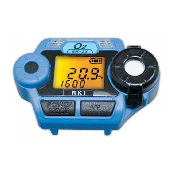
3. Press and hold the AIR button for about three seconds to allow the GasWatch 2 to set the fresh air reading. It will set the reading on the GW-2C and GW-2H to 0 ppm and on the GW-2X it will set the reading to 20.9% oxygen. - Page 27 GasWatch 2’s sensor. Assembling the Calibration Kit WARNING: Calibrate the GasWatch 2 in a non-hazardous environment. 1. Attach the calibration adapter to the unit. It opens up like a clothes pin and fits over the sensor area and retains itself over the sensor.
- Page 28 NOTE: If the gas reading is high enough (low enough for the GW-2X) when the unit enters Measuring Mode, an alarm condition will occur. Reset the alarm using the POWER/MODE button when the gas reading falls below (rises above for the GW-2X) the alarm point. 23 • Calibration GasWatch 2 Operator’s Manual...
-
Page 29: Maintenance
Maintenance This section describes troubleshooting procedures for the GasWatch 2. It also describes how to change the GasWatch 2’s battery as well as how to replace the sensor cover and gas sensor. WARNING: RKI Instruments, Inc. recommends that service, calibration, and repair of RKI instruments be performed by personnel properly trained for this work. -
Page 30: Replacing The Lithium Battery
Table 5: Troubleshooting the GasWatch 2 Probable Symptoms Recommended Action Causes • “FAIL” displays • The calibration 1. Check all calibration tubing during span or value may not for leaks or for any bad zero adjustment. match the connections. cylinder gas 2. - Page 31 1. Verify that the GasWatch 2 is off. 2. On the back of the unit, unscrew the two screws that retain the battery cover far enough so you can pull the cover away from the bottom case. The screws are held captive in the battery cover if you do not unscrew them too far.
-
Page 32: Replacing The Sensor
Replacing the Sensor WARNING: Replace the sensor in a non-hazardous environment. 1. Verify that the GasWatch 2 is off. 2. With a flat blade screw driver, gently pry off the sensor cap. It snaps onto the top case with two tabs. -
Page 33: Replacing The Sensor Cover
Replacing the Sensor Cover WARNING: Replace the sensor cover in a non-hazardous environment. 1. Verify that the GasWatch 2 is off. 2. With a flat blade screw driver, gently pry off the sensor cap. It snaps onto the top case with two tabs. -
Page 34: Replacing The Charcoal Filter Disk
Use a spring bar tool to remove the spring bars from the unit. A spring bar tool may be purchased from a jewelry supply shop or may be purchased from RKI Instruments, Inc. (see Parts List at the end of this manual). - Page 35 Be sure to remove the outer sleeve from the wrist band. 3. Insert the hollow sleeves and spring bars into the new wristband. 4. Install the new wristband onto the unit with a spring bar tool. GasWatch 2 Operator’s Manual Maintenance • 30...
-
Page 36: Parts List
Parts List Table 6 lists replacement parts and accessories for the GasWatch 2. Table 6: Parts List Part Number Description 06-1248RK Calibration kit tubing (specify length in feet) 07-0029RK Sensor gasket 07-6007RK O-ring for battery cover 10-1097RK Screw, for battery cover... -
Page 37: Appendix A: Mri Applications
Oxygen sensor Appendix A: MRI Applications When the GasWatch 2 is used in MRI applications or applications where a strong magnetic field is present on a regular basis, the magnetic field will cause damage to the instruments’s buzzer over time. This damage may eventually render the buzzer inoperable.
Need help?
Do you have a question about the GasWatch 2 and is the answer not in the manual?
Questions and answers