RKI Instruments GX-2009 Operator's Manual
Portable gas monitor
Hide thumbs
Also See for GX-2009:
- Operator's manual (74 pages) ,
- Quick reference manual (29 pages) ,
- User manual (2 pages)

Related Manuals for RKI Instruments GX-2009


Summary of Contents for RKI Instruments GX-2009
- Page 1 GX-2009 Portable Gas Monitor Operator’s Manual Part Number: 71-0158RK Revision: Q Released: 6/5/20 1.800.544.2843 www.calcert.com sales@calcert.com...
- Page 2 Typical calibration frequencies for most applications are between 1 and 3 months, but can be required more often or less often based on your usage. GX-2009 Operator’s Manual 1.800.544.2843 www.calcert.com sales@calcert.com...
- Page 3 Warranty RKI Instruments, Inc. warrants the GX-2009 sold by us to be free from defects in materials, workmanship, and performance for a period of two years from the date of shipment from RKI Instruments, Inc. This includes the instrument and the original sensors.
-
Page 4: Table Of Contents
Turning Off the GX-2009 ........ - Page 5 Recharging the GX-2009’s NiMH Batteries........57...
-
Page 6: Introduction
The GX-2009 offers a full range of features, including: •... -
Page 7: Specifications
AC or DC Charging Station, AC Charging Station Available For From 1 to 5 Instruments Accessories Other Accessories • IrDA/USB cable for downloading data to computer • Product CD, includes GX-2009 Data Logger Management Program and GX-2009 Setup Program • SDM-2009 Automatic Calibration Station • Hand Aspirated Sample Draw Adapter with Hose and Probe •... - Page 8 Approx. 70 H, 75 W, 25 D mm Weight: 4.6 oz. *The GX-2009 is also available set up for general hydrocarbons and calibrated to a combustible gas other than methane, such as isobutane. Consult RKI Instruments, Inc. for further information.
-
Page 9: Description
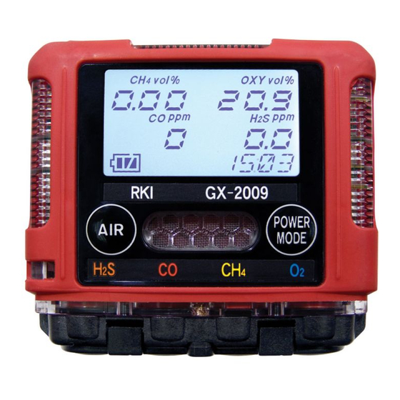
Description This section describes the GX-2009’s components and the charging station. These components include the GX-2009’s case, alligator and belt clips, sensor retainer, sensor retainer gasket, sensor cover retainer, scrubber filters, sensor cover, sensors, LCD, control buttons, printed circuit boards, alarm LED arrays, buzzer, vibrator, batteries, and charging station. -
Page 10: Case
A clear plastic window through which the LCD can be viewed is located on the front of the case. Three brass charging contacts that are used when the GX-2009 is placed in the charging station are on the back of the case. Four sensor diffusion ports are located on the bottom of the case. -
Page 11: Alligator & Belt Clips
Figure 3: Alligator and Belt Clips The alligator clip can be used to attach the GX-2009 to clothing or a belt. Teeth in the alligator clip’s jaws prevent the unit from slipping off. The alligator clip can be rotated to change how the instrument is oriented when worn. -
Page 12: Sensors
If the sensor cover becomes dirty, the response time and accuracy of the GX-2009 will be affected. Replace the sensor cover if it appears dirty. Sensors... -
Page 13: Lcd
The gas reacts in the sensor and produces a current proportional to the concentration of the target gas. The current is amplified by the GX-2009’s circuitry, converted to a measurement of gas concentration, and displayed on the LCD. -
Page 14: Printed Circuit Boards
Two NiMH (nickel metal hydride) batteries, each with an integral holder, supply 2.4 volts to power the GX-2009. The batteries will run the unit for up to 20 hours when no alarms have been activated during that time period. The batteries are designed to be charged while in the GX-2009 with the GX-2009 Charging Station. -
Page 15: Charging Station
Charging Station The GX-2009’s NiMH batteries are charged with the GX-2009 Charging Station. There are two types of charging stations available, the standard AC powered charging station and the optional vehicle plug DC powered charging station. AC Powered Charging Station The standard AC powered charging station is available in configurations that charge from one to five instruments at a time. - Page 16 Figure 5, and the five instrument station is shown in Figure 6. AC Adapter Adapter Jack Figure 5: GX-2009 Charging Station, Two Instrument Station AC Adapter Adapter Jack Figure 6: GX-2009 Charging Station, Five Instrument Station 16 •...
- Page 17 It uses the same charging base as the AC powered charging station. Vehicle Plug DC Adapter Adapter Jack Charging Base Instrument Adapter Jack Retaining Tabs Charging Contacts Charge LED Rear View Top View Figure 7: GX-2009 DC Powered Charging Station GX-2009 Operator’s Manual Description • 17 1.800.544.2843 www.calcert.com sales@calcert.com...
-
Page 18: Start Up
The alarm LED’s and buzzer will pulse several times. This screen will then remain on the display until the unit is turned off. The GX-2009 cannot be used until a complete calibration has been performed either by selecting AUTO CAL or ONE CAL in the Calibration Mode menu. - Page 19 The alarm LED’s and buzzer will pulse several times. This screen will then remain on the display until the unit is turned off. The GX-2009 cannot be used until a bump test has been performed. See “Performing a Bump Test in BUMP” on page 44 for bump test procedures.
- Page 20 TWA alarm setpoint for the CO and H S channels 8. If the GX-2009 experiences a sensor failure during start up, a screen indicating which sensor failed displays. In the example below, the CO sensor has failed. F A IL...
-
Page 21: Performing A Fresh Air Adjustment
The gas reading for the failed sensor will be replaced by “- - -”. Replace the failed sensor as soon as possible. 9. If Auto Zero Adjustment is set to On, then the GX-2009 will perform an automatic fresh air adjustment. -
Page 22: Turning Off The Gx-2009
4. The unit will take a few seconds to adjust the fresh air readings, then return to the Normal Operation Screen. Turning Off the GX-2009 1. Press and hold the POWER MODE button for about three seconds to turn off the unit. The buzzer will sound and the LCD back light will turn on. -
Page 23: Operation
Normal Operation When the GX-2009 comes out of its startup sequence, see “Start Up” on page 18, it enters Measuring Mode and is in normal operation if no alarm indications are taking place. It is advisable to perform a fresh air adjustment when the GX-2009 comes out of its startup sequence as described in “Start Up”. - Page 24 7. Press and release the POWER MODE button again to return to Measuring Mode. NOTE: If you do not press a button for 20 seconds while in Display Mode, the GX-2009 will return to Measuring Mode automatically and the backlight will turn off 30 seconds since the last button was pressed.
-
Page 25: Combustible Gas Detection
HC by using the GX-2009 Setup Program. See the GX-2009 Setup Program Operator’s Manual for information on how to set the combustible gas name. -
Page 26: Alarms
Alarm Indications The GX-2009 will sound an alarm, the LEDs will flash, and the unit will vibrate when one of the target gas concentrations rises above the Warning (low alarm) setpoint, or in the case of oxygen falls below the Warning setpoint, for that gas. - Page 27 Alarm Logic/Resetting Alarms The gas alarm logic can be set to either latching or self resetting with the GX-2009 Setup Program by setting the Alarm Pattern parameter. See the GX-2009 Setup Program Operator’s Manual for information on how to set the alarm logic. If Alarm Pattern is set to Latch, the gas alarms are latching.
- Page 28 3. Reset the alarm using the POWER MODE button once the alarm condition has cleared. 4. Calibrate the GX-2009 as described in “Performing a Span Adjustment in AUTO CAL” on page 35 or “Performing a Span Adjustment in ONE CAL” on page 40.
- Page 29 The GX-2009 is fully functional during a low battery warning. However, depending upon conditions, the GX-2009 has only two or three hours of operating time left after the low battery warning has been triggered. Recharge the battery pack as soon as possible as described in “Recharging the GX-2009’s NiMH Batteries”...
-
Page 30: Aspirator Adapter
Probe Figure 8: GX-2009 Aspirator Adapter 1. Turn on the GX-2009 as directed in “Start Up” on page 18. 2. Attach the sample adapter plate to the sensor side of the instrument. 3. Screw the probe onto the threaded end of the 10 ft. hose. -
Page 31: Data Logging
Peak Reading Screen. Data Logging The GX-2009 features the ability to log data to its internal memory and download it to a computer via the infrared communications port on the top left side. It logs gas readings during normal operation, alarm data, calibration data, and bump test data. -
Page 32: Calibration Mode
The optimum frequency of calibration depends heavily on how the GX-2009 is used. For example, instruments used daily may need to be calibrated weekly or monthly, while instruments that are used only a few times a year may need to be calibrated before each use. -
Page 33: Using Calibration Mode
BUMP TEST, there are no gas alarm indications. 1. Take the GX-2009 to a non-hazardous area and turn it off if it is on. 2. Press and hold the AIR button, then press and hold the POWER MODE button. When you hear a beep release the buttons. -
Page 34: Setting The Date & Time
Normal Mode. The AIR CAL menu item is available in Calibration Mode for convenience when performing a complete calibration. WARNING: Calibrate the GX-2009 in a non-hazardous environment. 1. Find a fresh air environment, an environment of normal oxygen content (20.9%) that is free of toxic and combustible gasses. -
Page 35: Performing A Span Adjustment In Auto Cal
S, 50 ppm CO, and a balance of nitrogen. If the H S channel on your GX-2009 is active, then use a 4-gas cylinder. If the H S channel on your GX-2009 is not active, you may use a 3-gas cylinder to adjust the span. The standard 3-gas cylinder consists of 50% LEL methane, 12% oxygen, 50 ppm CO, and a balance of nitrogen. - Page 36 “Performing a Fresh Air Adjustment” on page 34. 2. At the AUTO CAL screen, press and release the POWER MODE button. A screen appears that displays the calibration gas concentrations that the GX-2009 expects you to use. %LEL OXY vol% 12.0...
- Page 37 • Press and release the POWER MODE button to return to the screen that displays the calibration gas values. %LEL OXY vol% 12.0 CO ppm H2S ppm 25.0 AUTO CAL GX-2009 Operator’s Manual Calibration Mode • 37 1.800.544.2843 www.calcert.com sales@calcert.com...
- Page 38 Flow Figure 9: Calibration Kit Assembly 4. Push the adapter plate onto the GX-2009’s sensor face. Make sure the adapter plate is oriented as shown in Figure 10 below with the sensor names on the adapter plate matching up with the sensor names on the instrument.
- Page 39 7. Allow the gas to flow for two minutes. 8. Press and release the POWER button. 9. The GX-2009 will attempt to make a span adjustment on all channels. 10. If the span adjustment is successful, the LCD will show the following screen before returning to the AUTO CAL screen.
-
Page 40: Performing A Span Adjustment In One Cal
S, 50 ppm CO, and a balance of nitrogen. If the H S channel on your GX-2009 is active, then use a 4-gas cylinder so that you can calibrate all channels when necessary. If the H S channel on your GX-2009 is not active, you may use a 3-gas cylinder. - Page 41 Figure 11. To Fixed Flow Regulator Calibration Tubing T u b i n g Adapter Plate Flow Figure 11: Calibration Kit Assembly GX-2009 Operator’s Manual Calibration Mode • 41 1.800.544.2843 www.calcert.com sales@calcert.com...
- Page 42 5. Push the adapter plate onto the GX-2009’s sensor face. Make sure the adapter plate is oriented as shown in Figure 12 below with the sensor names on the adapter plate matching up with the sensor names on the instrument.
- Page 43 11. The GX-2009 will make the span adjustment and will return to the channel selection screen. %LEL - - - ONE CAL The channel that was just span adjusted will be displayed. 12. If you want to span adjust additional channels, repeat Step 3 through Step 11 for each channel while gas is still flowing.
-
Page 44: Performing A Bump Test In Bump
Performing a Bump Test in BUMP NOTE: Bump Test Function must be set to On using the GX-2009 User Setup Program in order for BUMP to appear in Calibration Mode. If Bump Test Function is set to Off, BUMP will not appear. See the GX-2009 User Setup Program Operator’s Manual for instructions. - Page 45 Flow Figure 13: Calibration Kit Assembly 4. Push the adapter plate onto the GX-2009’s sensor face. Make sure the adapter plate is oriented as shown in Figure 14 below with the sensor names on the adapter plate matching up with the sensor names on the instrument.
- Page 46 See “Troubleshooting” on page 56 to investigate the cause of the failure and replace the failed sensor or sensors if necessary. • Turn the regulator on/off knob clockwise to close it. 46 • Calibration Mode GX-2009 Operator’s Manual 1.800.544.2843 www.calcert.com sales@calcert.com...
- Page 47 %LEL OXY vol% CO ppm H2S ppm BUMP/CAL • To view the bump test gas readings, press the AIR button. %LEL OXY vol% 20.9 CO ppm H2S ppm BUMP/ GX-2009 Operator’s Manual Calibration Mode • 47 1.800.544.2843 www.calcert.com sales@calcert.com...
-
Page 48: Discharging The Batteries With The Refresh Function
The NiMH batteries used in the GX-2009 are resistant to this effect, but if you notice that the runtime is decreasing, run the REFRESH function two or three times and see if the runtime recovers. - Page 49 TURN OFF 5. Press and hold the POWER MODE button until the unit turns off, then release it. Recharge the GX-2009’s batteries. See “Recharging the GX-2009’s NiMH Batteries” on page 57. GX-2009 Operator’s Manual Calibration Mode • 49 1.800.544.2843...
-
Page 50: User Setup Mode
User Setup Mode This section describes the GX-2009 in User Setup Mode. User setup mode has the same menu items as Calibration Mode with the addition of the ALARM--P menu item which allows you to set the alarm points and the PASSWORD menu item which allows you to turn the password feature on or off and set the password. - Page 51 AIR button • immediately press the POWER MODE button and then release both buttons • the direction of adjustment when you press the AIR button is now reversed GX-2009 Operator’s Manual User Setup Mode • 51 1.800.544.2843 www.calcert.com sales@calcert.com...
-
Page 52: Setting The Date & Time
START item. START 10. At the START screen, press and release the POWER MODE button. The GX-2009 will begin its start-up sequence. The User Setup Mode menu items are described below in the order in which they appear while moving through User Setup Mode. -
Page 53: Setting The Alarm Points
In the example below, the combustible channel has been selected and the Warning alarm point is displayed flashing. %LEL WARNING 4. Use the AIR button to adjust the Warning setpoint to the desired value. GX-2009 Operator’s Manual User Setup Mode • 53 1.800.544.2843 www.calcert.com sales@calcert.com... -
Page 54: Setting The Password
PASSWORD menu item allows you to turn this feature on or off and enter a password if you turn it on. PASSWORD The factory setting for the password feature is oFF. 54 • User Setup Mode GX-2009 Operator’s Manual 1.800.544.2843 www.calcert.com sales@calcert.com... - Page 55 8. Repeat Step 5 through Step 7 until you have set all four of the digits. 9. When you save the last digit, the unit will return to the PASSWORD screen. PASSWORD GX-2009 Operator’s Manual User Setup Mode • 55 1.800.544.2843 www.calcert.com...
-
Page 56: Maintenance
Maintenance This section describes troubleshooting procedures for the GX-2009. It also describes how to recharge the GX-2009’s batteries, check the combustible sensor’s condition, replace the unit’s filters, sensor cover, and gas sensors. WARNING: RKI Instruments, Inc. recommends that service, calibration, and repair of RKI equipment be performed by personnel properly trained for this work. -
Page 57: Recharging The Gx-2009'S Nimh Batteries
49-2170RK-0X (where X = 1, 2, 3, 4, or 5) or RKI DC charger 49-2171RK. Use of other rechargeable batteries or chargers or charging of other rechargeable batteries in the GX-2009 will void the warranty. 1. Verify that the GX-2009 is off. - Page 58 If using a DC powered charging station, plug the 12 VDC vehicle plug adapter into a vehicle’s 12 VDC power socket. Power Supply Jack DC Adapter To Vehicle 12 VDC Charge LED Power Socket DC Powered Charging Station Figure 16: Connecting the Charging Station’s DC Adapter 58 • Maintenance GX-2009 Operator’s Manual 1.800.544.2843 www.calcert.com sales@calcert.com...
- Page 59 4. Put the GX-2009 in the charging base. Tabs at the top and bottom of the charging base retain the instrument. Retaining Tabs GX-2009 POWER MODE %LEL Figure 17: Putting the GX-2009 in the Charging Base 5. While the unit is being charged, the red charging LED on the top face of the charger is on.
-
Page 60: Replacing The Gx-2009'S Nimh Batteries
WARNING: Replace the batteries in a non-hazardous environment. Replace the battery set when it no longer holds a charge. 1. Verify that the GX-2009 is off. 2. Use a small phillips head screwdriver to remove the four screws that hold the two halves of the case together. - Page 61 Main Circuit Board Figure 21: NiMH Batteries 7. Remove each battery by gently pulling it away from the circuit board. Each battery has an integral holder that provides electrical connection to the circuit board. GX-2009 Operator’s Manual Maintenance • 61 1.800.544.2843 www.calcert.com...
-
Page 62: Checking The Combustible Gas Sensor's Condition
If you are not able to adjust the combustible gas reading to be at least 10% higher than the calibration gas concentration, then the sensor should be replaced as soon as possible. 62 • Maintenance GX-2009 Operator’s Manual 1.800.544.2843 www.calcert.com... -
Page 63: Replacing The Scrubber Filters
Filter Disk Figure 23: Removing the Sensor Retainer and Replacing the Scrubber Filters 1. Verify that the GX-2009 is off. 2. Unscrew the two screws that secure the sensor retainer and sensor cover retainer to the GX-2009 and remove them. -
Page 64: Replacing The Sensor Cover
Replacing the Sensor Cover WARNING: Replace the sensor cover in a non-hazardous environment. 1. Verify that the GX-2009 is off. 2. Unscrew the two screws that secure the sensor retainer and sensor cover retainer to the GX-2009 and remove them. - Page 65 5. Carefully insert the replacement sensor in the socket. Line up slots in H2S and CO sensors with tabs in case. Figure 25: Replacing the Sensors and Their Locations in the GX-2009 GX-2009 Operator’s Manual Maintenance • 65 1.800.544.2843 www.calcert.com...
- Page 66 6. Snap the sensor retainer back onto the case, then secure it to the GX-2009 with the two screws. The sensor retainer’s tabs that snap onto the case are keyed so you can only snap it to the case one way.
-
Page 67: Parts List
Parts List Table 7 lists replacement parts and accessories for the GX-2009. Table 7: Parts List Part Number Description 06-1248RK-03 Calibration kit tubing, 3 foot length 07-6021RK Sensor retainer gasket 10-1098RK Screw with washers, for alligator or belt clip installation... - Page 68 GX-2009 Portable Gas Monitor Operator’s Manual 71-0162RK GX-2009 User Setup Program Operator’s Manual 71-8002RK GX-2009 Product CD, includes Data Management Program, User Setup Program, and all operator’s manuals 81-GX01HSCO 58 liter four-gas cylinder, regulator, calibration plate, case & tubing 81-GX01HSCO- 34 liter aluminum four-gas cylinder, regulator, calibration plate, case &...
Need help?
Do you have a question about the GX-2009 and is the answer not in the manual?
Questions and answers