
Related Manuals for RKI Instruments VOC Pro


Summary of Contents for RKI Instruments VOC Pro
- Page 1 VOC Pro Operator’s Manual Part Number: 71-0530 Revision: P4 Released: 12/10/20 RKI Instruments, Inc. www.rkiinstruments.com...
- Page 2 Typical calibration frequen- cies for most applications are between 1 and 3 months, but can be required more often or less often based on your usage. 2 • VOC Pro Transmitter...
- Page 3 Product Warranty RKI Instruments, Inc. warrants gas alarm equipment sold by us to be free from defects in materials, workmanship, and performance for a period of one year from date of shipment from RKI Instruments, Inc. Any parts found defective within that period will be repaired or replaced, at our option, free of charge.
- Page 4 Danger Statements DANGER: The RKI Instruments Inc. VOC Pro is an ambient air Hazardous gas sensor assembly and only monitors in the immediate vicinity of the sensor housing. A site survey is required in order to determine the best placement and quantity of sensor assemblies. Improper installation can lead to an undetectable gas leak which could result in personal injury or loss of life.
-
Page 5: Table Of Contents
Mounting the VOC Pro ........ - Page 6 Appendix C: Modbus Register Map ..........70 6 • VOC Pro Transmitter...
-
Page 7: Overview
When the magnetic switch is toggled, an on-screen indicator will appear on the display screen, signifying that a connection was made. The VOC Pro display screen will always show the present concentration of gas being detected by the sensor assembly. -
Page 8: Specifications
Specifications Table 1 lists specifications for the VOC Pro. Table 1: Specifications Target Gas Volatile organic compounds (VOCs) • isobutylene calibration standard for 10.6 and 11.7 eV sensors • benzene calibration standard for 10.0 eV sensor Sampling Method Diffusion Detection Range and... - Page 9 Weight 6 lbs. WARNING: When using the VOC Pro, you must follow the instructions and warnings in this manual to assure proper and safe operation of the VOC Pro and to minimize the risk of personal injury. Be sure to maintain and periodically calibrate the VOC Pro as described in this manual.
-
Page 10: External Description
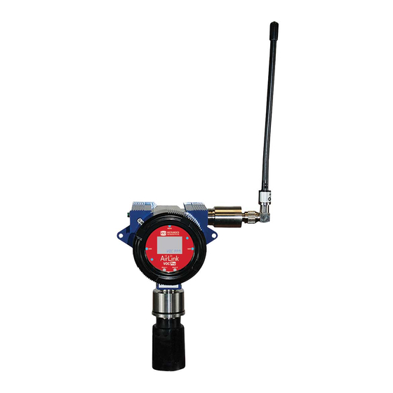
External Description Figure 1: VOC Pro External Component Location MENU button Sensor housing assembly Front panel thumbscrew Rain guard Enclosure Magnetic tool Explosion proof plug Alarm 1 LED SUB button ADD button Mounting hole Enclosure lid locking screw Alarm 2 LED... -
Page 11: Internal Description
Internal Description Figure 2: Internal Component Location RS-485 Modbus terminal block Sensor housing socket Fault terminal block Not installed in VOC Pro Power input/4-20 mA output Relay 1 terminal block (if relays installed) terminal block Not installed in VOC Pro Relay 2 terminal block (if relays installed) VOC Pro Transmitter •... -
Page 12: Exploded Drawing
Exploded Drawing Figure 3: Exploded Diagram Enclosure lid Sensor housing base Internal system Sensor element Not installed in VOC Pro Rain guard Enclosure body Sensor housing cap with flame arrestor Not installed in VOC Pro Analog sensor board Not installed in VOC Pro... -
Page 13: Installation
Select a site that is representative of the monitoring environment and where the target gas is likely to accumulate or where it is most likely to leak. The VOC Pro should not be installed near an entrance, air intake, or exhaust point. - Page 14 Figure 4: Mounting the VOC Pro 14 • VOC Pro Transmitter...
-
Page 15: Wiring Power And 4-20 Ma Output
The VOC Pro has several basic wiring configurations, dependent upon the desired usage and functionality intended by the end-user. All VOC Pro units require +12 to +35 Volts of wired DC power to operate. Data communication from the device, through either the 4-20 output or the RS-485 Modbus connection, to an external location are optional. - Page 16 VOC Pro. You will connect the opposite end of the cable’s drain wire to the controller’s chassis (earth) ground. 5. Route the cable or wires leading from the VOC Pro through one of the conduit hubs at the controller housing.
-
Page 17: Connecting Rs-485 Modbus
1. If necessary, unscrew the enclosure lid and pull the internal system out by the thumbscrews. CAUTION: Be sure power to the VOC Pro is off before pulling out the internal system. 2. Feed the RS-485 cable through the power hub and into the enclosure. - Page 18 Figure 6: Modbus Wiring NOTE: If an RKI controller is not used, the VOC Pro can be connected to a Programmable Logic Controller (PLC) for RS-485 Modbus data communications. For integration and setup, refer to the Modbus Register Map found in Appendix C of this manual.
-
Page 19: Connecting Relays/Alarms
1. If necessary, unscrew the enclosure lid and pull the internal system out by the thumbscrews. CAUTION: Be sure power to the VOC Pro is off before pulling out the internal system. 2. Locate the relay terminal blocks on the radio/relay board. - Page 20 5. Connect the external power source’s “+” terminal (GRAY) to the COM terminal on the relay terminal block. Figure 7: Relay Wiring 20 • VOC Pro Transmitter...
-
Page 21: Connecting The Fault Terminal
1. If necessary, unscrew the enclosure lid and pull the internal system out by the thumbscrews. CAUTION: Be sure power to the VOC Pro is off before pulling out the internal system. 2. Locate the power (RED) and ground (BLACK) wires on the alarming device. -
Page 22: Closing The Enclosure
2. Using the thumbscrews, gently push to seat the internal system into the mounting posts. NOTE: The thumbscrews on the VOC Pro function ONLY as thumb-holds for ease in removal of the internal system from the base of the enclosure. Do NOT attempt to loosen or tighten the thumbscrews when opening or closing the enclosure. -
Page 23: Start Up
Start Up This section describes procedures to start up the VOC Pro and place the VOC Pro into normal operation. 1. Complete the installation procedures described earlier in this manual. 2. Verify that the power wiring is correct and secure. -
Page 24: Operation
Normal Operating Mode While in normal operating mode, the VOC Pro continuously samples the air and updates the measured concentration of the target gas on the display screen. The display, when in normal operation, appears as shown below. -
Page 25: Magnetic Buttons
SUB button Powering the Device When power is first applied to the VOC Pro, the unit automatically powers on and begins the startup sequence. The directions below describe how to power off and power on the VOC Pro once power has been applied. -
Page 26: Manual Reset For Activated Latching Alarms
The unit continuously registers that the system is in fault. When the fault is corrected, the unit will return to normal operating mode. For a list of the fault codes and warning symbols of the VOC Pro, and their associated meaning, see page 44. -
Page 27: Accessing Menus
Settings menu from the normal operating screen, press and release the MENU button once and the menu will open and show on the display. NOTE: After 5 minutes of no interaction with the device, the unit will automatically return to normal operating mode. VOC Pro Transmitter • 27... -
Page 28: Product Settings And Configuration
The Product Settings and Configuration menu allows the end-user to tailor the device settings to meet their required specifications and/or site conditions. The VOC Pro continues monitoring for gas while in the Product Settings and Configuration menu. The Product Settings and Configuration menu consist of the following screens: •... -
Page 29: System Information
NOTE: Triggering VOC Pro relays will also simulate Alarm 1 and Alarm 2 relays at the controller. Controllers cannot distinguish between real and simulated data received. When the controller relays are triggered, alarm devices will perform as intended, initiating emergency procedures as if a harmful or toxic gas was actually present. To prevent this from occurring, set the controller to calibration mode before performing the alarm test. -
Page 30: Zero/Calibration Timer Information
• The serial number of the sensor assembly. This screen is for informational purposes only. 1. If necessary, enter the Product Settings and Configuration menu by pressing and holding the MENU button for 6 seconds. 30 • VOC Pro Transmitter... -
Page 31: Latching And Auto Resetting Relay Settings
MUST be below the alarm set-point before the alarm can be deactivated. The alarms will NOT activate, even in the presence of gas, until you have exited the menu mode for approximately 1 minute. VOC Pro Transmitter • 31... -
Page 32: Relay Fail-Safe Setting
The fail-safe setting should ONLY be enabled to provide enhanced safety protection when the fault terminal CANNOT be used. The factory default settings on the VOC Pro for Relay 1 and Relay 2 fail-safe are No (Off). 32 • VOC Pro Transmitter... - Page 33 If the fault terminal cannot be used, RKI Instruments recommends one of the following configurations: Recommended Configurations for Relay Fail-Safe Setting Power Source Relay Wiring Fail-Safe Outcome VOC Pro Normally-Closed (NC) No (Off) Normal Operation: Closed Alarm Activation: Open VOC Pro...
-
Page 34: Fault Terminal Fail-Safe Setting
3. Use the ADD button to select manual calibration and the SUB button to select auto calibration. 4. Press and release the MENU button to move through the Product Settings and Configuration menu or to exit to the normal operating mode screen. 34 • VOC Pro Transmitter... -
Page 35: Modbus Address Setting
Modbus address field. The VOC Pro uses the original Modbus RTU over the RS-485 link. RS-485 Modbus has 255 addresses, ranging from 1 to 255. Eight of the addresses are used for internal system settings, leaving addresses 1 to 247 available for your device. -
Page 36: Modbus Baud Setting
The VOC Pro’s default Modbus baud setting is 9600 bps. The RS-485 Modbus communication parameters used in the VOC Pro are 8 data bits, no parity bit, and 1 stop bit (8-N-1) these parameters are fixed and cannot be changed. Some devices come with different Modbus baud rates. - Page 37 The factory default settings on the VOC Pro for the 4-20 mA offset are 4.00 mA for the zero offset and 20.00 mA for the full-scale offset. 1. If necessary, enter the Product Settings and Configuration menu by pressing and holding the MENU button for 6 seconds.
-
Page 38: Display Screen Contrast Setting
The factory default setting on the VOC Pro for the display screen contrast is 29, approximately 45% of the contrast scale. The contrast setting ranges from 1 to 64. -
Page 39: Return To Factory Default Settings
Return to Factory Default Settings Returning the VOC Pro to its factory default settings will reset all customization of the device, including the zero and calibration settings of the sensor element. A factory default does not change the gas type. -
Page 40: Reset Zero & Calibration Values
Configuration menu or to exit to the normal operating mode screen. NOTE: If the VOC Pro is reset to the factory default settings, ALL configuration steps MUST be repeated and the device MUST then be zeroed and calibrated for proper operation of the device. -
Page 41: Operation Settings
All alarm set-points are field adjustable up to 60% of the full scale gas concentration. The factory default setting on the VOC Pro for Alarm 1 is 10% of full scale and 15% of full scale for Alarm 2. The Alarm 1 set-point should NEVER be programed to a higher setting than the Alarm 2 set-point. - Page 42 Sensor Alarm 2 Setting 1. From normal operating mode, press and release MENU until the Alarm 2 setting screen appears. 2. Use the ADD and SUB buttons to increase and decrease the Alarm 2 set-point, respectively. 42 • VOC Pro Transmitter...
-
Page 43: Maintenance
The VOC Pro may be adversely affected by the exposure to certain airborne substances. Loss of sensitivity or corrosion may be gradual, if such materials are present in sufficient concentrations. -
Page 44: Troubleshooting
Use of the VOC Pro in these environments may require more frequently scheduled maintenance to ensure safe and reliable system performance. -
Page 45: Desiccant Replacement
Each VOC Pro comes with a desiccant bag installed in the junction box. The contents are blue when it is dry. As the desiccant absorbs moisture, it turns amber. Periodically check the desiccant and replace it if it has turned amber. - Page 46 5. Do not touch the lamp window with your fingers as this may contaminate the window with finger oil. At this point it is recommended that the finger cots be used on the fingers handling the lamp. Finger cots are included with the lamp cleaning kit. 46 • VOC Pro Transmitter...
- Page 47 10. Hold the lamp in one hand being careful not to touch the lamp window with your fingers. 11. With the other hand collect a small amount of powder (aluminum oxide for 10.0 eV and 10.6 eV sensors; anhydrous methanol for 11.7 eV sensors) on a cotton swab. VOC Pro Transmitter • 47...
- Page 48 19. Press in the electrode stack firmly to ensure that the stack wing clips are engaged and the faces of the stack and sensor body are flush. 48 • VOC Pro Transmitter...
-
Page 49: Replacing The Pid Lamp
Ordering the Correct Replacement Lamp It’s important to order the correct replacement lamp for your PID sensor. 1. Look at the part number label on the side of your PID sensor. VOC Pro Transmitter • 49... - Page 50 2. Unscrew and remove the sensor housing cap from the sensor housing base. Set aside. 3. Gently unplug the sensor element from the sensor housing board. 4. Place the PID sensor face down on a flat clean working surface. 50 • VOC Pro Transmitter...
- Page 51 The lamp should be supported by the O-ring. 12. Continuing to hold the electrode stack between your forefinger and thumb, carefully insert the lamp into the lamp cavity in the sensor ensuring that the lamp remains in position. VOC Pro Transmitter • 51...
-
Page 52: Replacing The Pid Electrode Stack
DO NOT use any metal objects or tools to remove the sensor. The electrode stack can last for the life of the PID sensor if the VOC Pro is used in a very clean, controlled environment. When used in a heavily contaminated or dirty environment, the electrode stack may only last a month. - Page 53 4. Place the PID sensor face down on a flat clean working surface. NOTE: At this point it is recommended that the finger cots be used on the fingers handling the lamp. Finger cots are included with the lamp cleaning kit. VOC Pro Transmitter • 53...
- Page 54 13. Press in the electrode stack firmly to ensure that the stack wing clips are engaged and the faces of the stack and sensor body are flush. 54 • VOC Pro Transmitter...
-
Page 55: Sensor Replacement
DO NOT use any metal objects or tools to remove the sensor. 1. Press and hold the SUB button for approximately 6 seconds, until “OFF” shows on the display screen. 2. Unscrew the rain guard. VOC Pro Transmitter • 55... - Page 56 4. Gently unplug the sensor element from the sensor housing board. 5. Plug the new sensor element into the sensor housing board. Ensure that the pins on the sensing element align with the sockets on the sensor housing board. 56 • VOC Pro Transmitter...
-
Page 57: Fuse Replacement
DO NOT use any metal objects or tools to remove the fuses. 1. Disconnect or turn off power to the VOC Pro. 2. Unscrew the enclosure lid and set it aside. 3. Grab the thumbscrews and gently lift the internal system out of the enclosure. It can rest on the edge of the enclosure. - Page 58 9. Using the thumbscrews, gently push to seat the internal system into the mounting posts. NOTE: The thumbscrews on the VOC Pro function ONLY as thumb-holds for ease in removal of the internal system from the base of the enclosure. Do NOT attempt to loosen or tighten the thumbscrews when opening or closing the enclosure.
-
Page 59: Calibration Frequency
If air quality cannot be guaranteed, a cylinder of zero air will be required to properly zero the sensor. 1. While the product is in normal operating mode, press the MENU button to activate the Operation Settings menu. VOC Pro Transmitter • 59... - Page 60 4. If the sensor is not in clear air: a. Unscrew and remove the rain guard from the assembly. b. Install the calibration cup to the VOC Pro’s sensor housing. c. Screw the regulator into the zero air calibration cylinder.
-
Page 61: Calibrating The Sensor (Manual Cal)
Configuration menu, see page 62. 1. Unscrew and remove the sensor housing cap from the assembly. 2. Install the calibration cup to the VOC Pro’s sensor housing. 3. Screw the regulator into the calibration cylinder. 4. Use the sample tubing to connect the regulator to the calibration cup. -
Page 62: Calibrating The Sensor (Auto Cal)
5. Unscrew and remove the rain guard from the assembly. 6. Install the calibration cup to the VOC Pro’s sensor housing. 7. Screw the regulator into the calibration cylinder. 8. Use the sample tubing to connect the regulator to the calibration cup. - Page 63 The sensor element will need to be replaced before completing the zero and calibration process. 12. Turn the regulator knob clockwise to close the regulator. 13. Press the MENU button until the normal operating screen appears. VOC Pro Transmitter • 63...
-
Page 64: Parts List
Parts List Table 7 lists replacement parts and accessories for the VOC Pro. Table 7: Parts List Part Number Description 33-0560RK PID sensor electrode stack, low range 10.6 eV sensor, 2 stacks 33-0560-01 PID sensor electrode stack, low range 10.6 eV sensor, 1 stack 33-0562 PID sensor electrode stack, high range 10.6 eV sensor... - Page 65 Table 7: Parts List Part Number Description 82-0301 Anhydrous methanol PID lamp cleaning kit, with electrode stack removal tool, for 11.7 eV sensor’s lamp ONLY VOC Pro Transmitter • 65...
-
Page 66: Appendix A: Introduction To 4-20 Ma Current Loop Signals
4 mA representing the lowest end of the range and 20 mA the highest. The relationship between the current loop and the gas value is linear. In addition, the VOC Pro uses values below 4 mA to indicate special status conditions, as shown below: 4-20 mA Ranges... - Page 67 (DMM), or current meter, may be used in conjunction with the controller and/or to test the 4-20 mA current loop signal. To measure the current, place the meter probes in line with the current loop. VOC Pro Transmitter • 67...
-
Page 68: Appendix B: Modbus Communications
Daisy chains may be used for power, analog signals, digital data, or a combination thereof. For the purposes of the VOC Pro, the term daisy chain refers to multiple devices connected in a series to form a single long line of devices, connected via the wiring patterns embedded within each device. - Page 69 Shielded, in areas of 1,000 Feet Gauge high noise Long* 1,000 Feet to 18 to 20 Shielded, in areas of 4,000 Feet Gauge high noise (*) Terminating resistor may be required for the last device in the daisy-chain. VOC Pro Transmitter • 69...
-
Page 70: Appendix C: Modbus Register Map
Register Address 1: Hexadecimal numbers Register Address 2: Decimal numbers R/W: Read/Write capable data R: Read-only data FLOAT: Floating point number ENUM: Enumeration UINT: Unsigned integer INT: Integer BFLD: Bit Field (*): Limited by precision 70 • VOC Pro Transmitter... - Page 71 VOC Pro Modbus Register MAP Enumeration Keys Register Address 4: Gas Type Response Gas Type H2S – Hydrogen Sulfide SO2 – Sulfur Dioxide O2 – Oxygen CO – Carbon Monoxide CL2 – Chlorine CO2 – Carbon Dioxide LEL – Combustible Gas VOC –...
- Page 72 1 – Yes (On) Relay 2: Latch/Auto 0 – Auto Reset Reset 1 - Latch Relay 1: Latch/Auto 0 – Auto Reset Reset 1 – Latch Register Address 19/25: Calibration Type Response Calibration Type Manual Calibration Auto Calibration 72 • VOC Pro Transmitter...
Need help?
Do you have a question about the VOC Pro and is the answer not in the manual?
Questions and answers