RKI Instruments GD-70D Series Operating Manual
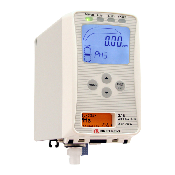
Gas detector head
Hide thumbs
Also See for GD-70D Series:
- Quick reference manual (8 pages) ,
- Operating manual (142 pages) ,
- Operating manual (142 pages)
Table of Contents
Advertisement
Quick Links
Gas Detector Head
Part Number: 71-0446
Revision: P1
Released: 7/11/19
Request for the Customers
•
Read and understand this operating manual before using the detector.
•
You must operate the detector in accordance with the operating manual.
•
Regardless of warranty period, we shall not make any compensation for accidents and damage
caused by using this product.
The compensation shall be made only under the warranty policy of products or parts
replacement.
•
Because this is a safety device, daily and biannual maintenance must be performed.
•
If you find abnormalities in the detector, please contact our local representative immediately.
GD-70D Series
Operating Manual
Advertisement
Table of Contents

Subscribe to Our Youtube Channel
Related Manuals for RKI Instruments GD-70D Series


Summary of Contents for RKI Instruments GD-70D Series
-
Page 1: Request For The Customers
Gas Detector Head GD-70D Series Operating Manual Part Number: 71-0446 Revision: P1 Released: 7/11/19 Request for the Customers • Read and understand this operating manual before using the detector. • You must operate the detector in accordance with the operating manual. -
Page 2: Table Of Contents
<Contents> Request for the Customers ..................1 Outline of the Product ....................4 1-1 Preface ......................4 1-2 Product Purpose ....................4 1-3 Definition of DANGER, WARNING, CAUTION and NOTE ......5 1-4 Method of confirmation for CE marking type ............ 5 Important Notices on Safety .................. - Page 3 10-10 Storing the GD-70D ................115 Troubleshooting ......................116 Product Specifications ....................119 12-1 Common Specifications ............... 119 12-2 Specifications for Each Model ............. 119 12-3 Specifications for Each Sensor Type ........... 120 12-4 Full Scale and Alarm Points ..............123 Calibration Parts List......................
-
Page 4: Outline Of The Product
Outline of the Product Preface Thank you for choosing our GD-70D Series gas detector head. Please verify that the model number of the product you purchased is included in the specifications on this manual. This manual explains how to use the detector and its specifications. It contains information required for using the detector properly. -
Page 5: Definition Of Danger, Warning, Caution And Note
Definition of DANGER, WARNING, CAUTION and NOTE This message indicates that improper handling may cause serious damage DANGER on life, health or assets. This message indicates that improper handling may cause serious damage WARNING on health or assets. This message indicates that improper handling may cause minor damage on CAUTION health or assets. -
Page 6: Important Notices On Safety
Important Notices on Safety Danger Statements DANGER This is not an explosion-proof device. You must not use it to detect gases exceeding the lower limit of explosion. Warning Statements WARNING Power Supply Before turning on the detector, always check whether the voltage is properly applied. Do not use an unstable power supply because it may cause malfunctions. -
Page 7: Caution Statements
Definition of Terms Caution Statements CAUTION Do not use a transceiver (walkie-talkie) near the detector. Radio waves from a transceiver near the detector or its cables may disrupt detector operation. When using a transceiver, it must be used in a place where it disturbs nothing. Do not turn the detector on less than 5 seconds after it was turned off. -
Page 8: Product Components
Product Components Main Unit and Standard Accessories <Main Unit> <Standard Accessories> • Operating manual • Protective rubber cap (to be removed when using the detector) • Dedicated handling lever (for wiring) • Dust filter • Interference gas removal filter (to be supplied with sensor units for certain gases) GD-70D - 8 -... -
Page 9: Outline Drawing
<Pyrolyzer Unit (PLU-70)(Option)> Pyrolyzer Unit * This is needed in “pyrolyzer + electrochemical type (ESU)” and “pyrolyzer + pyrolysis-particle type (SSU)”. For more information on the pyrolyzer unit (PLU-70), see the separate operating manual. Outline Drawing M5 mounting hole Display Operating switch Sensor unit display GAS OUT... -
Page 10: Names And Functions For Each Part
Names and Functions for Each Part The detector consists of the following units. Pump unit Wall-mounted unit Main unit Sensor unit CAUTION Each unit consists of precision parts. When a unit is detached, be careful not to drop it. Dropping the unit compromises its original performance or causes malfunctions. - Page 11 ① MODE key Used to enter User and Maintenance Mode. It is also used to cancel or skip in a specific mode. ② TEST/SET key Used to enter the test mode. It is used for confirmation in a specific mode. ▲...
- Page 12 <Mounting Plate> The mounting plate gets installed to the installation site. The main unit connects to the mounting plate using the 10-point terminal plate. Mounting hole 10-point terminal plate: Connections for power supply, signal cables and other external wires. Locking lever: Locks the main unit to the mounting plate. <Sensor Unit>...
- Page 13 • Electrochemical Do not disassemble the sensor unit because it contains electrolyte. If contact type (ESU) occurs, rinse the area immediately with a large quantity of water. • The sensor unit identifies the storage direction. Put the sensor unit in the dedicated case while handling it.
-
Page 14: Operation Diagrams
• Galvanic cell type Do not disassemble the sensor unit because it contains electrolyte. If contact (OSU) occurs, rinse the area immediately with a large quantity of water. • The sensor unit must be stored under normal temperature/humidity in a clean place away from direct sunlight. - Page 15 <Tubing Diagram> GD-70D - 15 -...
-
Page 16: Installation
Installation Requirements All users must follow the operating precautions. Ignoring the precautions may damage the detector, resulting in inaccurate gas detection. CAUTION • After you receive the detector, start using the detector within the specified operation start limit of the sensor unit. - Page 17 Do not install the detector in a place exposed to direct sunlight or sudden changes in the temperature. Avoid installation locations where the detector is exposed to direct sunlight or radiant heat (infrared rays emitted from a high- temperature object), and where the temperature changes suddenly.
-
Page 18: Precautions For System Designing
Precautions for System Designing CAUTION • An unstable power supply and noise may cause malfunctions or false alarms. Using a stable power supply The external output and alarm contact of the detector may be activated when the power is turned on, when momentary blackout occurs, or when the system is being stabilized. -
Page 19: Proper Use Of Alarm Contact
Proper use of alarm contact The alarm contact of the detector is used to transmit signals to activate an external buzzer, alarm lamp or rotating lamp. Do not use the detector for controlling purpose (e.g., controlling the shutdown valve). CAUTION •... -
Page 20: Installing The Detector
Installing the Detector NOTE To use the pyrolyzer unit (PLU-70), also refer to the individual operating manual. CAUTION • Before installing the detector, remove the protective rubber caps from the GAS IN and GAS OUT fittings. If the detector is turned on while the rubber caps are still in place, the pump and sensor may be damaged. - Page 21 CAUTION • The detector must be installed in the correct orientation to ensure its performance. Install the detector as shown on the following example. (* The detector must also remain in this orientation during transportation.) <Correct Installation Orientation> Wall Ceiling Wall Floor <Installing the Mounting Plate>...
-
Page 22: Wiring The Detector
5. Attach the mounting plate to the installation surface using two or three M5 screws. Recommended mounting screw (M5) Length of 8 mm or more Flat washer of φ10 mm or less (small round) 6. Leave the main unit detached from the mounting plate and continue to the wiring section. Wiring the Detector NOTE To use the pyrolyzer unit (PLU-70), also refer to the separate operating manual. - Page 23 <Terminal Plate Specifications> Top handling slot Conductive part Specifications of terminal plate • Rated voltage: 250 VDC • Rated current: 16 A Cage clamp/spring Wiring hole Driver slot Connection conditions • Cable: 0.08 - 2.5mm • Bare wire length: 8 - 9 mm •...
- Page 24 <Wiring to the Terminal Plate> ● 4 - 20 mA/NT/EA Specification - - 24 VDC 4 - 20 mA ALM1 ALM2 FAULT contact contact contact ●LN Specification - - 24 VDC LONWORKS ALM1 ALM2 FAULT output contact contact contact NOTE For a 3-wire type 4 - 20 mA, terminal 2 is used as common for the power supply and the 4-20 mA output.
- Page 25 Push the dedicated 4. Use the handling lever included with the GD-70D or a handling lever to flathead screwdriver to make wiring connections. open the terminals. 5. Route the wires through the wiring opening in the bottom of Insert 1 wire per the mounting plate.
- Page 26 Generic Controller Wiring GD-70D Terminal Plate DC24V ALM1 ALM2 FAULT 4-20mA 9 10 Device Power Controller or Recording Fault Alarm Device Device Device - (DCGround) Power + 24 VDC Alarm 2 4 - 20 mA In (FB) Device Device Power Cable Shield Alarm 1 Device...
- Page 27 PLC or DCS Wiring GD-70D Terminal Plate DC24V ALM1 ALM2 FAULT 4-20mA 9 10 Power Supply Device + 24 VDC Power - 24 VDC Fault Alarm Device Cable Shield Device PLC or DCS Power Alarm 2 Device Device Power Cable Shield Alarm 1 Device GD-70D...
- Page 28 RM-5003 Wiring GD-70D Terminal Plate 4-20mA ALM1 ALM2 FAULT DC24V Device Power Fault Alarm RM-5003 Device Device Power Alarm 2 Device Device Cable Shield Power Alarm 1 Device GD-70D - 28 -...
- Page 29 Ethernet Wiring GD-70D Terminal Plate DC24V 4-20mA ALM1 ALM2 FAULT RJ45 Connector Power Supply Device + 24 VDC Power - 24 VDC Fault Alarm Device Cable Shield Device Power Alarm 2 Device PC or Switching Device Power Alarm 1 Device GD-70D - 29 -...
- Page 30 PoE Wiring GD-70D Terminal Plate DC24V 4-20mA ALM1 ALM2 FAULT 9 10 RJ45 Connector Device Power Fault Alarm Device Device Power Alarm 2 Switching Hub Device PC or (with PoE Functionality) Device Power Alarm 1 Device GD-70D - 30 -...
- Page 31 LON Wiring GD-70D Terminal Plate DC24V ALM1 ALM2 FAULT WORKS Power Supply Device + 24 VDC Power - 24 VDC Fault Alarm Device Cable Shield Device Power Alarm 2 Device Device Power Cable Shield Alarm 1 Device GD-70D - 31 -...
- Page 32 RM-70NT Wiring (for GD-70D-NT) GD-70D-NT Terminal Plate ALM2 FAULT DC24V 4-20mA ALM1 9 10 Power Supply (24 VDC) Blocking Filter (B/F) Device Power Fault Alarm Device Upper Unit (RM-70NT) Device DC 24V (+) Power DC 24V (-) Alarm 2 Device Device Cable Shield Power...
- Page 33 <Grounding> Use the grounding terminal to connect the detector to your grounding circuit. WARNING • Before turning on the detector, do not forget to connect it to a grounding circuit. • For stable operation of the detector and safety, it must be connected to a grounding circuit.
-
Page 34: Making Tubing Connections
Making Tubing Connections NOTE To use the pyrolyzer unit (PLU-70), also refer to the individual operating manual. 1. The tube nut, ferrule, and tubing insert are shipped uninstalled and the open GAS IN and GAS OUT fittings are plugged with protective rubber caps. Remove the rubber caps from the GAS IN and GAS OUT fittings. -
Page 35: Disposal
WARNING • The detector is designed to draw gas under normal atmospheric pressure. If excessive pressure is applied to the GAS IN or GAS OUT fitting, detected gases may be leaked from its inside, thus leading to dangers. Be sure that excessive pressure is not applied to the detector during use. CAUTION •... -
Page 36: Operation
Operation Preparation for Start-up Before connecting a power supply, read and understand the following precautions. Ignoring these precautions may cause an electric shock or damage the detector. • Connect the detector to a grounding circuit. • Ensure the wiring is correctly connected to the external circuit. •... - Page 37 <Warm-up Sequence> The warm-up taking approximately 25 seconds to complete. Power On ● ↓ PW:POWER :Lamp on ○ A1:ALM1 :Lamp off A2:ALM2 F:FAULT ────── ● ○ ○ ○ Initial Clear WARM UP ↓ ↓ ● ○ ○ ○ 15.0ppm Specifications SIH4 Display ↓...
-
Page 38: Turning Off The Detector
Turning Off the Detector To turn off the detector, open the switch cover on the bottom of the main unit, and turn "OFF" the power switch. Then, turn off the power supply (24 VDC) to the detector. WARNING • When the detector is turned off, an alarm may be activated on the upper (central) system. Before turning off the detector, the inhibit (point skip) on the upper (central) system must be activated. -
Page 39: Modes
WARNING • When the detector enters each mode from Detection Mode while an alarm is activated, the alarm contact is released. <Detection Mode> Flow Rate Indicator Because the suction flow rate of the detector is automatically adjusted by the flow rate control function, the flow rate, in principal, does not need to be controlled. - Page 40 Mode Item LCD Display Details Maintenance Gas Introduction Display 2-0 GAS TEST Perform the gas introduction test. Mode (see pg. Zero Adjustment 2-1 ZERO Perform the zero adjustment. Span Adjustment 2-2 SPAN Perform the span adjustment. Last Calibrated Date 2-3 LAST CAL Show the last calibrated date.
-
Page 41: Detection Mode
Detection Mode Gas Alarm Activation A gas alarm is activated when the concentration of detected gas reaches or exceeds the alarm setpoint. This section describes alarms assuming an auto-reset operation. NOTE The alarm setpoint (first alarm and second alarm) is factory set. The alarm delay time (standard: 2 seconds) is enabled in the detector to prevent a false activation. - Page 42 <Contact Activation> The contact is activated when the gas concentration reaches or exceeds the alarm setpoint. The contact activation is reset automatically when the gas concentration drops below the alarm setpoint. <Contact Activation (Auto-reset)> In case of Auto-reset setting, the contact is activated when the gas concentration reaches or exceeds the alarm setpoint value.
- Page 43 "Alarm Pattern (L-H)" "Alarm Pattern (L-LL)" (* oxygen deficiency alarm) GD-70D - 43 -...
- Page 44 <Contact Activation (Self-latching)> In case of Self-latching setting, the contact is activated when the gas concentration reaches or exceeds the alarm setpoint value. The alarm indication lamp blinks during warning. It changes to a light after reset is performed. It turns off when the gas concentration drops below the alarm set point value. "Alarm Pattern (H-HH)"...
- Page 45 "Alarm Pattern (L-H)" GD-70D - 45 -...
- Page 46 "Alarm Pattern (L-LL)" <Response to Gas Alarm> When a gas alarm is triggered, take actions in accordance with your company’s safety practices for a gas alarm. In general, take the following actions. 1. Check the reading of the detector. NOTE If a gas leak is momentary or if the alarm is triggered by noise, the reading may already have dropped by the time you get to the instrument to check it.
-
Page 47: Fault Alarm Activation
Fault Alarm Activation A fault alarm is triggered when the detector detects abnormalities. After a fault alarm is triggered, the FAULT lamp (yellow) lights up and an error message is displayed on the LCD. Determine the causes and take appropriate actions. After the detector is successfully returned from the fault, it restarts and goes through a normal warmup procedure. - Page 48 ● LN Specification Specifications LONWORKS (LN) Signal transmission LONWORKS method Transmission KPEV-S path Transmission 78kbps rate Transmission Max 2700m distance * When bus topology (Double ended termination ) is used. Connection load ― resistance Example of Gas Concentration and External Output 4 - 20 mA Specification (Maintenance output: 2.5 mA setting) External output...
- Page 49 <Communication Specifications> GD-70D- Power-line The detector is used in a local network formed with a multi-display unit (RM- communication 70NT) as the base unit. For more information, see the operating manual of the system multi-display unit. GD-70D- Ethernet The detector offers functions that work in liaison with external software using a standard network protocol.
-
Page 50: Other Functions
Other Functions <Suppression Function> Some sensors are influenced by environmental changes (temperature, humidity, and other characteristics) or interference gases which may cause the reading to vary in fresh air. The suppression function is used to hide (suppress) the variation of the reading under the set suppression value, so that the display indicates zero (or 20.9% for oxygen) until the reading exceeds the set suppression value. - Page 51 <Zero Follower Function> Zero Follower Off Some sensors (ESU and SSU types) have sensitivity variations after being used for a long Reading period of time. The zero follower function uses program manipulation to correct for sensitivity variations in the zero reading. Zero point Time * The zero drift of the sensor appears as the reading.
- Page 52 <Calibration History/Alarm Trend History/Event History Functions> The detector and the sensor unit have their own history functions. To use these functions, contact RKI. <Sensor Unit Automatic Recognition Function> The detector can automatically recognize when a new sensor has been installed. If a replacement sensor of the same type is installed, the detector will display a “C-01 CHG UNIT”...
-
Page 53: About Lonworks (Ln Specification)
About LONWORKS (LN specification) <Binding method> WARNING • When adjustment is completed, press the MODE key and be sure to return to detection mode. (When left in user mode, it automatically returns to detection mode after 10 hours.) ≪User mode≫ ●... - Page 54 GD-70D-LN LonWorks Diagram Open-lLoop Sensor Functional Block nvoConc SNVT_ppm_f nvoNstate SNVT_state Mandato Implementation Specific nviReset SNVT_lev_disc nvoAlarmS SNVT_switch nvoFaultS SNVT_switch nvoGasName SNVT_str_asc nvoHertBeat SNVT_state nviComand nvoComand SNVT_str_asc SNVT_str_asc Virtual Function Block nciMaxSendTM SNVT_time_sec nciMinSendTM SNVT_time_sec nciMaxSendTl SNVT_time_sec nciMinSendTl SNVT_time_sec nciMaxSendHB SNVT_time_sec GD-70D - 54 -...
- Page 55 NO. Variable name Variable type Contents It is the same as the current density output. nvoConc SNVT_ppm_f Floating point of 16 BIT synchronizes with the display of the detection part. It is the same as the current density output. nvoNstate SNVT_state Status of 16 BIT expresses measurement unit, alarm, breakdown etc.
- Page 56 You can select the transmission status with the setting point of nciMaxSendHBb(12) ・nciMaxSendHB (12) = Asec --> (6) transmit every Asec. ・nciMaxSendHB (12) = 0sec --> (6) don’t transmit every Asec. It outputs to nvoComand (14) for input data of nviComand (13).
-
Page 57: Alarm Test Mode
Alarm Test Mode Alarm Test Mode generates dummy signals that imitate gas concentration signals in order to check the alarm LED activation and the transmission to external circuits. WARNING • Before starting the alarm test (transmission test), prepare for false alarms by disabling alarms or alerting appropriate personnel. - Page 58 Return to Detection Mode Press the TEST key for 3 seconds. GD-70D - 58 -...
-
Page 59: User Mode
User Mode WARNING After the adjustment is completed, do not forget to press the MODE key to return to Detection Mode. User Mode ● ○ ○ ○ Detection Mode 0.0ppm Press the MODE key for three seconds. SIH4 ↓ ↓ User Mode ●... - Page 60 ● ○ ○ ○ → 1-5.70D VER 1- 5 01234 Show the program version of the main unit. 70D VER 56AB MAINTENANCE MAINTENANCE ↓ ↑ ▲ ▼ ● ○ ○ ○ → 1-6.UNIT VER 1- 6 01234 Show the program version of the installed sensor unit.
- Page 61 ○ ○ ○ → See Maintenance 1-9. M MODE 1- 9 Mode on page 65. Switch to the regular maintenance mode. M MODE MAINTENANCE ↓↑ ▲ ▼ To 1-1. ZERO NOTE • Communication output setting 1-8 (COM SET) is displayed only for EA specification. •...
- Page 62 <Zero Adjustment "1-1"> This is used to perform the zero adjustment. Before starting the zero adjustment, let the detector draw fresh air or zero air until the reading is stable. For oxygen units, "1-1" is called the span adjustment instead of the zero adjustment. In this case, fresh air or zero air must be applied to the detector to ensure the reading is 20.9 vol%.
- Page 63 <Setpoint Indicator "1-2"> Use this menu item to check important setpoints. Setpoints cannot be changed in User Mode. Setpoint Display ● ○ ○ ○ From Detection Mode, press the 0.0ppm MODE key for three seconds. SIH4 ↓ ↓ ● ○ ○...
- Page 64 ● ○ ○ ○ Sensitivity Correction ON/OFF (If ESU sensor installed) S ASSIST MAINTENANCE ↓ ↑ ▲ ▼ To First Alarm Setpoint Indicator GD-70D - 64 -...
-
Page 65: Maintenance Mode
Maintenance Mode WARNING After the adjustment is completed, do not forget to press the MODE key to return to Detection Mode. (If the detector remains in Maintenance Mode, it automatically returns to Detection Mode in ten hours.) Maintenance Mode Item LCD Display Details Gas Introduction Display... - Page 66 Maintenance Mode Item LCD Display Details Environmental Setting 2 2-10 SETTING2 Function settings • Address setting (ADDRESS) ⇒ ⇒ • Date/Time setting (DAY TIME) • Zero suppression value setting (SUPPRESS) • Zero suppression type setting (SUP TYPE) • Alarm test mode contact setting (TEST RLY) •...
- Page 67 Maintenance Mode ●: Lamp on PW: POWER ○: Lamp off A1: ALM1 A2: ALM2 ● ○ ○ ○ From Detection Mode, press 0.0ppm F: FAULT and hold the MODE key for three seconds. SIH4 ↓ ↓ ● ○ ○ ○ 1-8.M MODE 1- 8 ▲...
- Page 68 ● ○ ○ ○ → 2-3.LAST CAL 2- 3 12:00 Show the most recent calibration date. LAST CAL 2009.01.01 MAINTENANCE MAINTENANCE ↓ ↑ ▲ ▼ ● ○ ○ ○ → 2-4.BIAS 2- 4 0 mV Show the bias voltage "BIAS" of electrochemical type (ESU) BIAS BIAS...
- Page 69 ● ○ ○ ○ → Environmental 2-10.SETTING2 2-10 Setting 2 ⇒P74 Enter the environmental setting 2 menu. SETTING2 MAINTENANCE ↓ ↑ ▲ ▼ ● ○ ○ ○ → For information on 2-11.PL DATA 2-11 Pyrolyzer Data Show the pyrolyzer data when the pyrolyzer unit (PLU- Display, see "PLU- PL DATA...
-
Page 70: Environmental Setting 1 "2-9
Environmental Setting 1 "2-9" The Environmental Setting 1 menu allows you to view and/or change operation settings. Environmental Setting 1 ● ○ ○ ○ From Detection Mode, press 0.0ppm and hold the MODE key for three seconds. SIH4 ↓ ↓ ●... -
Page 71: Alarm Value Setting "2-9" - "Set 1
● ○ ○ ○ ⇔ Alarm Value Setting SET 1.ALM P SET 1 ⇒P71 Change the alarm setpoints. ALM P MAINTENANCE ↓ ↑ ▲ ▼ ● ○ ○ ○ ⇔ SET 2.ALM DLY SET 2 Set the alarm delay time. Use the ▲... - Page 72 ● ○ ○ ○ Then press and hold the SET key again - - - - for three seconds. M MODE MAINTENANCE ↓ ↓ ● ○ ○ ○ 2-0.GAS TEST 2- 0 The first item in Maintenance Mode will display. GAS TEST MAINTENANCE ↓...
-
Page 73: Fault Alarm Test "2-9" - "Set 4
Fault Alarm Test "2-9" - "SET 4" ● ○ ○ ○ From Detection Mode, press and hold 0.0ppm the MODE key for three seconds. SIH4 ↓ ↓ ● ○ ○ ○ 1-8.M MODE 1- 8 ▲ Press the key until the Maintenance M MODE Mode screen displays. -
Page 74: Environmental Setting 2 "2-10
● ○ ○ ○ Fault Test ON/OFF With ON displayed, press the SET key to activate the fault alarm. F TEST With OFF displayed, press the SET key MAINTENANCE to deactivate the fault alarm. ↓ ↑ (You can also press the MODE key to ▲... - Page 75 ● ○ ○ ○ 2-0.GAS TEST 2- 0 The first item in Maintenance Mode will display. GAS TEST MAINTENANCE ↓ ↓ ● ○ ○ ○ 2-10. SETTING2 2- 10 ▲ Press the key until the SETTING2 screen displays. SETTING2 MAINTENANCE Press the SET key.
- Page 76 ● ○ ○ ○ ⇔ SET 5.TEST4-20 SET 5 Set the external output for an alarm test. TEST4-20 TEST4-20 Select either ON or OFF, and MAINTENANCE MAINTENANCE then press the SET key to ↓↑ ▲ ▼ confirm the selection. When ON is selected, the output follows the reading even during an alarm test.
- Page 77 ● ○ ○ ○ SET 10. FLT PTRN SET 10 This is a setting screen of the fault alarm activation. Do not FLT PTRN change the setting when the MAINTENANCE detector is used in a normal way, because it determines how the detector functions.
- Page 78 ● ○ ○ ○ ⇔ SET 15. MNT OUT SET 15 2.5mA Set the external output for Maintenance Mode. MNT OUT MNT OUT Select either 2.5 mA, 4.0 MAINTENANCE MAINTENANCE mA, HOLD (previous value), ↓↑ or 4 - 20 mA (tracks display ▲...
-
Page 79: Date/Time Setting "2-10" - "Set 1
● ○ ○ ○ ⇔ SET 19.PUMP CK SET 19 Set the pump drive level diagnosis. PUMP CK PUMP CK Select either ON or OFF, and MAINTENANCE MAINTENANCE then press the SET key to ↓↑ ▲ ▼ confirm the selection. When ON is selected, the message "FLOW"... - Page 80 ↓ ↓ ● ○ ○ ○ SET 1.DAY TIME SET 1 Press the SET key. DAY TIME MAINTENANCE ↓ ↓ ● ○ ○ ○ Date/Time Setting Display 12:00 Press the SET key. 2009.01.01 MAINTENANCE ↓ ● ○ ○ ○ Year Setting 12:00 Select the number by pressing the ▲...
-
Page 81: Energized/De-Energized Contact Setting "2-10" - "Set 6
Energized/De-Energized Contact Setting "2-10" - "SET 6" ● ○ ○ ○ From Detection Mode, press 0.0ppm and hold the MODE key for three seconds. SIH4 ↓ ↓ ● ○ ○ ○ 1-8.M MODE 1- 8 ▲ Press the key until the M MODE Maintenance Mode screen displays. - Page 82 ● ○ ○ ○ ⇔ First Alarm Contact ▲/▼ Setting AL1 RLY AL1 RLY Select either nd(De- Energized)/nE(Energized), MAINTENANCE MAINTENANCE and then press the SET key to confirm the selection. (Press the MODE key to skip this menu.) Factory setting is nd. ↓...
-
Page 83: Ethernet Setting "2-10" - "Set 18
ETHERNET Setting "2-10" - "SET 18" <ETHERNET Setting> ● ○ ○ ○ From Detection Mode, press 0.0ppm and hold the MODE key for three seconds. SIH4 ↓ ↓ ● ○ ○ ○ 1-8.M MODE 1- 8 ▲ Press the key until the M MODE Maintenance Mode screen displays. - Page 84 ● ○ ○ ○ MAC Address Check There are MAC addresses from MAC1 MAC 1 to MAC6. Select one MAINTENANCE using ▲ and ▼ keys ↓↑ and display them one by ▲ ▼ one in the same way. * MAC addresses are (MAC2 - fixed values unique to the unit.
- Page 85 ↓↑ ▲ ▼ ● ○ ○ ○ ⇔ DHCP Setting Select either ON/OFF, and then press the SET DHCP DHCP key to confirm the MAINTENANCE MAINTENANCE selection. ▲↓↑▼ |↑ When ON is selected, an IP address is automatically obtained || DHCP from the DHCP server.
-
Page 86: Maintenance
Maintenance This is a critical instrument for incident prevention and safety. To maintain the performance of the detector and improve its reliability, perform regular maintenance. NOTE To use the pyrolyzer unit (PLU-70), also refer to the individual operating manual. 10-1 Maintenance intervals and items •... - Page 87 Detection Gas Range Calibration Instructions Br2 (Bromine) 0 - 1.00 ppm Calibrating with a Surrogate Gas (Sensors with Factors) on page 93 BTBAS (Bis[tertiary-butyl- 0 - 15.0 ppm Calibrating with a Surrogate Gas (Sensors with Factors) on amino]silane) page 93 C2H2 (Acetylene) 0 - 2,000 ppm Calibrating with a Humidifier (MOS Sensors) on page 103...
- Page 88 Detection Gas Range Calibration Instructions COF2 (Cobalt difluorine) 0 - 6.00 ppm Calibrating with a Surrogate Gas (Sensors with Factors) on page 93 DEA (Diethylamine) 0 - 15.0 ppm Calibrating with a Surrogate Gas (Sensors with Factors) on page 93 DMA (Dimethylamine) 0 - 15.0 ppm Calibrating with a Surrogate Gas (Sensors with Factors) on...
- Page 89 Detection Gas Range Calibration Instructions IPA (Isopropyl alcohol) 0 - 2,000 ppm Calibrating with a Humidifier (MOS Sensors) on page 103 0 - 100 %LEL Calibrating with a Surrogate Gas (Sensors with Factors) on page 93 N2O (Nitrous oxide) 0 - 500 ppm Calibrating with a Demand Flow Regulator on page 90 N2H4 (Hydrazine) 0 - 5.00 ppm...
-
Page 90: Calibrating With The Target Gas
Sulphur dioxide (SO2): 5 ppm 3 hours Calibration Equipment • Demand flow regulator (RKI Instruments, Inc. recommends that you dedicate one regulator each for Cl2 and H2S and that you not use that regulator for any other gas) • Calibration tubing •... - Page 91 Accessing Maintenance Mode 0.0ppm From Detection Mode, press and hold the MODE key for three seconds. SIH4 ↓ ↓ 1-8.M MODE 1- 8 Press the ▲ key until the Maintenance Mode screen displays. (For GD- M MODE 70D-EA units, the Maintenance Mode screen is item 1-9.) MAINTENANCE ↓...
- Page 92 Performing a Span Adjustment 2-2. SPAN 2- 2 Press the ▲ key until the SPAN screen SPAN displays. MAINTENANCE Press the SET key. Connect Gas Use the calibration tubing to connect the demand flow regulator to the tubing stub on the GAS IN fitting.
-
Page 93: Calibrating With A Surrogate Gas (Sensors With Factors)
↓ CAUTION Return to 2-2.SPAN Exhaust gas must be collected in the exhaust bag or discharged through the exhaust line. Returning to Detection Mode Store the components of the calibration kit in a safe place. Reconnect the dust filter and inlet line to the GAS IN fitting. Press and hold the MODE key to return to Detection Mode. - Page 94 Calibration Equipment for Gases Needing Dilution • 0.5 LPM fixed flow regulator (RKI Instruments, Inc. recommends that you dedicate one regulator each for Cl2 and that you not use that regulator for any other gas) •...
- Page 95 Phosphine does not come in cylinders of 0.1 ppm concentration so you need to determine how much to dilute the cylinder that you have. For example, a cylinder of 0.5 ppm PH3 diluted 1 part gas to 4 parts 0.5 ������������ ��������3 nitrogen (5 parts total) would give you 0.1 ppm PH3: ×...
- Page 96 15. Clamp down on the hose clamp to prevent the release of gas from the gas bag. 16. Remove the gas bag from the regulator. 17. Unscrew the regulator from the 100% N2 cylinder. 18. Continue to Entering Calibration Mode below. Preparing for Calibration –...
- Page 97 Zero Adjustment Completed 0.0ppm 0.0ppm The instrument will indicate whether the zero adjustment passed (OK) or failed (NG) and ZERO OK ZERO NG will return to 2-1.ZERO automatically. MAINTENANCE MAINTENANCE ↓ ↓ Return to 2-1.ZERO Return to 2-1.ZERO Performing a Span Adjustment 2-2.
- Page 98 Span Adjustment 8.0ppm Using the ▲ or ▼ keys, adjust the reading to match the concentration in the gas bag SPAN VAL multiplied by the conversion factor on the MAINTENANCE sensor OR to the value listed in the table at the beginning of this section.
-
Page 99: Calibrating With A Gas Bag (Calibrating With Hcl)
Calibration Equipment – No Dilution Needed • 6 LPM fixed flow regulator (RKI Instruments, Inc. recommends that you dedicate one regulator for use with HCl and that you not use that regulator for any other gas) •... - Page 100 Preparing for Calibration – 1:1 Dilution Needed Filling the Gas Bag RKI Instruments, Inc. recommends screwing a nitrogen calibration cylinder onto the fixed flow regulator and purging the regulator for 30 seconds before starting the calibration process. 1. If not already installed, install the hose and hose clamp on the gas bag.
- Page 101 2-0.GAS TEST 2- 0 The first item in Maintenance Mode will display. GAS TEST MAINTENANCE Performing a Zero Adjustment 2-1. ZERO 2- 1 Press the ▲ key until the ZERO screen ZERO displays. MAINTENANCE Press the SET key. ↓ Current Concentration Value Display 1.1ppm Press the SET key to perform the zero adjustment.
- Page 102 Disconnect Gas Close the gas bag’s hose clamp and immediately remove the gas bag from the tubing stub on the GD-70D’s GAS IN fitting. Disconnect the calibration tubing from the tubing stub on the GAS IN fitting. ↓ ↓ Span Adjustment 8.0ppm Using the ▲...
-
Page 103: Calibrating With A Humidifier (Mos Sensors)
10-6 Calibrating with a Humidifier (MOS Sensors) The calibration instructions in this section apply ONLY to the sensors listed in the table below. If your sensor is not listed in the table below, you will need to follow the instructions outlined in one of the other calibration sections. - Page 104 1 month or more Calibration Equipment • Demand flow regulator (RKI Instruments, Inc. recommends that you do not use a demand flow regulator that has previously been used for Cl2 or H2S to calibrate a MOS sensor) • 6” humidifier tube •...
- Page 105 ↓ ↓ 2-0.GAS TEST 2- 0 The first item in Maintenance Mode will display. GAS TEST MAINTENANCE Performing a Zero Adjustment 2-1. ZERO 2- 1 Press the ▲ key until the ZERO screen ZERO displays. MAINTENANCE Press the SET key. ↓...
- Page 106 Disconnect Gas Disconnect the humidifier from the tubing stub on the GAS IN fitting. Hold the humidifier assembly by the clear tubes at the ends when installing or removing the humidifier to avoid damaging the humidifier. Do not hold the humidifier tube itself.
-
Page 107: Calibrating A Pyrolyzer Unit
15 ppm 2 hours Calibration Equipment • Demand flow regulator (RKI Instruments, Inc. recommends that you do not use a demand flow regulator that has previously been used for Cl2 or H2S to calibrate a pyrolyzer unit) • Calibration tubing •... - Page 108 Then press and hold the SET key again for three seconds. - - - - M MODE MAINTENANCE ↓ ↓ 2-0.GAS TEST 2- 0 The first item in Maintenance Mode will display. GAS TEST MAINTENANCE Performing a Zero Adjustment 2-1. ZERO 2- 1 Press the ▲...
- Page 109 Accept Reading 2.0ppm Press the SET key when the reading has stabilized. SPAN GAS * The reading must be above 10% of the full MAINTENANCE scale value in order to continue. CAUTION Do not press the SET key before the reading is stabilized. Disconnect Gas Disconnect the calibration tubing from the tubing stub on the pyrolyzer’s GAS IN fitting.
-
Page 110: Flow Rate Adjustments
10-8 Flow Rate Adjustments <Flow Rate Manual Adjustment "2-6"> The 2-6 FLOW menu item allows the user to manually increase or decrease the flow. The flow rate of the detector is normally automatically adjusted to 0.5 L/min. In order to perform a manual adjustment, you must first turn off the auto-adjustment function (found in Maintenance Mode item 2-10 SET-11). - Page 111 <Flow Rate Default Set "2-5"> Regardless of whether the flow rate is manually or automatically set, when the reading on the flow rate indicator is incorrect (due to aging degradation, improper flow rate default set, or other reasons), it must be set to provide the right flow rate.
-
Page 112: Replacing Parts
WARNING After the adjustment is completed, do not forget to press the MODE key to return to Detection Mode. 10-9 Replacing Parts <Replacing the Sensor Unit> 1. Push the two buttons at the top of the main unit down to open the front cover. - Page 113 4. Pry the sensor unit lid off of the sensor unit body. 5. Remove the circuit board. Be very careful not to damage the white connector. 6. Remove the old battery. 7. Install a new battery. 8. Reinstall the circuit board being careful not to damage the white connector. 9.
- Page 114 <Replacing the External Dust Filter> Because the external dust filter may gradually get dirty or clogged over the time, it must be replaced. Check the external dust filter, and then replace it as necessary. Frequency of replacement will depend on the operating conditions. 1.
-
Page 115: Storing The Gd-70D
<Replacing the Flow Sensor> The flow sensor should be replaced every 5 years. The flow sensor is not user-serviceable and must be replaced by RKI. 10-10 Storing the GD-70D The detector must be stored under the following environmental conditions. 1. In a dark place under the normal temperature and humidity away from direct sunlight 2. -
Page 116: Troubleshooting
Troubleshooting This guide discusses frequently-seen malfunctions but does not discuss all malfunctions. If the detector shows a symptom which is not explained in this manual, or if it still has malfunctions even though remedial actions are taken, please contact RKI. NOTE To use the pyrolyzer unit (PLU-70), also refer to the individual operating manual. - Page 117 Symptom/Display FAULT Causes Actions ○ Flow Rate Warning Unstable flow caused by a Replace the pump unit as described on page deteriorated pump. 114. FLOW Unstable flow caused by Replace the dust filter as described on page 114. clogged dust filter. Unstable flow caused by bent Fix the defective parts.
- Page 118 <Reading Abnormalities> Symptoms Causes Actions The reading rises (drops for Drifting sensor. Perform a zero adjustment (AIR adjustment). oxygen) and stays there. Presence of interference gas. Disturbances by interference gases, such as solvents, cannot be eliminated completely. For information on actions, such as installing a removal filter, please contact RKI.
-
Page 119: Product Specifications
Product Specifications 12-1 Common Specifications Display LCD (Digital and Bar Meter Display) 0.5L/min ±10% Flow Rate Displays Gas name display/Flow rate indicator/Mode display/Communication status display/Pyrolyzer connection display Alarm Display First: ALM1 lamp on (Red) Second: ALM2 lamp on (Red) Fault: FAULT lamp on (Yellow), fault code displayed on LCD Alarm Activation Auto-reset or self-latching (fault alarm is auto-reset only) Alarm Contact... -
Page 120: Specifications For Each Sensor Type
GD-70D-EA GD-70D-LN Transmission Digital transmission: Ethernet LONWORKS (LN) System (10BASE-T/100BASE-TX) Analog transmission: 3-wire type analog transmission (Common cable for power and signal <Power, Signal, Common>) or 2-wire type analog transmission Transmission Digital transmission: Ethernet LONWORKS Specification Analog transmission: 4 - 20 mA DC (no- insulation/load resistance under 300 Ω) Recommended Digital transmission: Ethernet cable... - Page 121 OSU *5 Detection New ceramic Semiconductor Galvanic cell type principle Gas to be Combustible gas Combustible gas Oxygen detected Toxic gas Detection range See Full Scale and Alarm See Full Scale and Alarm See Full Scale and Alarm Points on page 123 Points on page 123 Points on page 123 Detection method...
- Page 122 Detection NDIR principle (Non-Dispersive Infrared Hot-wire Semiconductor Absorption) Gas to be detected Detection range See Full Scale and Alarm Points See Full Scale and Alarm on page 123 Points on page 123 Detection method Pump suction type Alarm setpoint See Full Scale and Alarm Points See Full Scale and Alarm value on page 123...
-
Page 123: Full Scale And Alarm Points
12-4 Full Scale and Alarm Points Detection Gas Full Scale Alarm 1 Alarm 2 AsH3 (Arsine) 0 - 0.20 ppm 0.05 ppm 0.10 ppm B2H6 (Diborane) 0 - 0.30 ppm 0.10 ppm 0.20 ppm BCl3 (Boron trichloride) 0 - 15.0 ppm 5.00 ppm 10.0 ppm Br2 (Bromine) - Page 124 Detection Gas Full Scale Alarm 1 Alarm 2 COS (Carbonyl sulfide) 0 - 2,000 ppm 500 ppm 1,000 ppm 0 - 90.0 ppm 30.0 ppm 60.0 ppm COF2 (Cobalt difluorine) 0 - 6.00 ppm 2.00 ppm 4.00 ppm DEA (Diethylamine) 0 - 15.0 ppm 5.0 ppm 10.0 ppm...
- Page 125 Detection Gas Full Scale Alarm 1 Alarm 2 NO (Nitric oxide) 0 - 100 ppm 5 ppm 10 ppm NO2 (Nitrogen dioxide) 0 - 9.00 ppm 3.00 ppm 6.00 ppm 0 - 15.0 ppm 5.0 ppm 10.0 ppm O2 (Oxygen) 0 - 5.00% 4.00% 4.00%...
-
Page 126: Calibration Parts List
Calibration Parts List General Parts Description Part Number Humidifier, 6”, with tubing (for MOS sensor calibration) 33-2001RK-01 Dispensing valve for filling gas bag, for 17 liter and 34 liter steel calibration 81-1001RK cylinders (cylinders with external threads) Regulator with gauge and knob for filling gas bag, 6 LPM, for 34 liter aluminum, 81-1051RK-60 58 liter, and 103 liter calibration cylinders (cylinders with internal threads) Regulator, demand flow type, for 34 liter aluminum, 58 liter, and 103 liter... - Page 127 Cylinder Description Part Number COS (carbonyl sulfide): 40 ppm in air, 58 liter calibration cylinder 81-0188RK-02 H2 (hydrogen): 100 ppm in air, 34 liter steel calibration cylinder 81-0033RK-01 H2 (hydrogen): 100 ppm in air, 103 liter calibration cylinder 81-0033RK-03 H2 (hydrogen): 200 ppm in air, 34 liter steel calibration cylinder 81-0000RK-51 H2 (hydrogen): 250 ppm in air, 34 liter steel calibration cylinder 81-0032RK-01...
- Page 128 Cylinder Description Part Number SO2 (sulfur dioxide): 5 ppm in nitrogen, 34 liter aluminum calibration cylinder 81-0170RK-04 Zero air, 34 liter steel calibration cylinder 81-0076RK-01 Zero air, 103 liter calibration cylinder 81-0076RK-03 GD-70D - 128 -...
-
Page 129: Replacement Parts List
Replacement Parts List General Parts Description Part Number Downloading cable 47-5060RK Dust filter 33-0165RK-01 Flow sensor 31-1011-01 Pump 30-1020RK Tubing nut, ferrule and post, 4 x 6 mm 17-2500RK-01 Tubing nut, ferrule and post, 1/4 x 5/32” 17-2503RK-01 Wiring tool lever 46-5100RK ESU Type Sensor Description Part Number... - Page 130 ESU Type Sensor Description Part Number HBr (Hydrogen bromide) 0 - 6.00 ppm sensor ESU-23E-HBR-06 HBr (Hydrogen bromide) 0 - 9.00 ppm sensor ESU-23E-HBR-09 HCl (Hydrogen chloride) 0 - 6.00 ppm sensor ESU-23E-HCL-06 HCl (Hydrogen chloride) 0 - 15.0 ppm sensor ESU-23E-HCL-15 HCN (Hydrogen cyanide) 0.9 - 15.0 ppm sensor ESU-23DH-HCN...
- Page 131 SGU Type Sensor Description Part Number C2H4 (Ethylene) 0 - 2000 ppm sensor SGU-8521-C2H4-2 C2H5OH (Ethanol) 0 - 2000 ppm sensor SGU-8521-C2H5OH C3H6 (Propylene) 0 - 5000 ppm sensor SGU-8511-C3H6-5 C3H8 (Propane) 0 - 2000 ppm sensor SGU-8511-C3H8-2 C3H8 (Propane) 0 - 5000 ppm sensor SGU-8511-C3H8-5 C4F6 (Hexafluorabutadiene) 0 - 200 ppm sensor SGU-8521-C4F6A...
- Page 132 Definition of Terms External Dust Filter When the detector is used in a dusty environment, it is recommended that a dust filter be installed in the inlet line. vol% Gas concentration indicated in the unit of one-hundredth of the volume. Gas concentration indicated in the unit of one-millionth of the volume.
- Page 133 Detection principle <Electrochemical Type> The electric potential between the working electrode and reference electrode is kept at a certain level by a potentiostat circuit. The gas to be detected is electrolyzed directly at the working electrode. Because the current generated is proportional to the gas concentration, the gas concentration can be determined by measuring the current between the working electrode and the opposite...
- Page 134 <Pyrolysis-Particle Type> When the gas to be detected is heated to several hundred degrees, particulate solid oxides are formed. This is a sensor to detect particles formed in such a way by using the α ray absorbing method. Structure (Pyrolyzer) This unit consists of a pyrolyzer, which heats gas to several Heater Heat insulator...
- Page 135 The detector has the pyrolysis-particle type sensor, which is a radioisotope-equipped device. It is examined in accordance with the regulations on "Article 12 - 3 of Act on Prevention of Radiation Disease Due to Radioisotopes, etc." (Nuclear Safety Technology Center, a certification and registration body), and certified as a specified designing certification device, which is regarded as a device causing little radiation damage.
- Page 136 Safety of the radioisotope 241Am (37 KBq) used in the pyrolysis-particle type sensor The pyrolysis-particle type sensor installed in the gas detector uses the radioisotope 241Am radiation source (18.5 KBq x 2 = 37 KBq). A specified designing certification device must satisfy the specified threshold for "1 cm dose equivalent rate at a point 10 cm away from the surface of the device"...
- Page 137 <New Ceramic Type> When a combustible gas burns on the surface of a highly active new ceramic oxidation catalyst in catalytic combustion, the new ceramic-type sensor measures resultant temperature changes by measuring the resistance changes in the heat-resistant alloy wire coil. The sensor consists of two elements: A detecting element having a heat-resistant alloy wire coil with an ultrafine particle (new ceramic) oxidation catalyst sintered on it together with a carrier and a temperature- compensating element with a mixture of gas-inert alumina and glass sintered on it.
- Page 138 <Semiconductor Type> Metal dioxide can measure gas concentration based on changes in the electric conductivity of semiconductor caused by gas accumulated on its surface. RL: Load resistance Vo: Output voltage VH: Heater voltage Vs: Sensor voltage Special precautions for this principle 1.
- Page 139 <Galvanic Cell Type> By immersing precious metal and lead in electrolyte and connecting them with a lead wire, a battery can be made (galvanic cell). When oxygen passes through the barrier, a deoxidizing reaction occurs at the precious metal electrode while an oxidizing reaction occurs at the lead electrode.
- Page 140 <NDIR (Non-Dispersive Infrared Absorption Type> IR light enters the cell and gas absorbs the beam, so the absorption rate and the gas concentration will correlate. The IR detector detects the IR light and will put it out as gas concentration. The band pass filter only lets specific wavelength that is absorbed by the target gas.
- Page 141 <Hot-Wire Semiconductor Type> The hot-wire semiconductor type sensor detects a change in resistance of the platinum wire coil integrated in a metal oxide semiconductor whose resistance value changes by contact with a gas as gas concentration. This is a highly sensitive gas detection sensor suitable for low concentrations. D: Detecting element C: Compensating element...
-
Page 142: Warranty Policy
This warranty is expressly in lieu of any and all other warranties and representations, expressed or implied, and all other obligations or liabilities on the part of RKI Instruments, Inc. including but not limited to, the warranty of merchantability or fitness for a particular purpose. In no event shall RKI Instruments, Inc. be liable for indirect, incidental, or consequential loss or damage of any kind connected with the use of its products or failure of its products to function or operate properly.
Need help?
Do you have a question about the GD-70D Series and is the answer not in the manual?
Questions and answers