
Related Manuals for Banner DXM700-Bx


Summary of Contents for Banner DXM700-Bx
- Page 1 DXM700-Bx Wireless Controller Instruc- tion Manual Original Instructions p/n: 207894 Rev. M July 26, 2023 © Banner Engineering Corp. All rights reserved.
-
Page 2: Table Of Contents
Contents Contents ..........................2 Chapter 1 DXM700-Bx System Overview DXM Hardware Configuration Overview..............................6 DXM Automation Protocols................................... 8 DXM Modbus Overview....................................8 DXM Modbus Registers ..................................9 DXM Configuration Software ..................................10 Dimensions ........................................ 11 Chapter 2 Quick Start Guide Device Setup ......................................13 Apply Power to the Controller ................................13 Binding and Site Survey (DXM100) .............................. - Page 3 Change the Device Name ................................... 69 Chapter 10 Accessories...................... 71 Chapter 11 Product Support and Maintenance File System and Archive Process ................................73 Update Your DXM Processor Firmware Using the DXM Configuration Software..................74 Clear the Password on DXM700-Bx, DXM1000-Bx, or DXM1200-Bx Models ..................74 DXM700 Documentation ................................... 74 DXM Support Policy ....................................75 Firmware Updates ....................................75 Website Information .................................... 75 Feature Requests ...
- Page 4 FCC and ISED Certification, 900 MHz, 1 Watt Radios ........................79 FCC Notices......................................79 FCC and ISED Approved Antennas..............................79 FCC and ISED Certification, 2.4GHz..............................80 FCC Notices......................................80 FCC and ISED Approved Antennas..............................81 International Certifications for Sure Cross® Radios ........................... 81 Warnings........................................82 Banner Engineering Corp Limited Warranty............................... 19 Document Information ....................................84...
-
Page 5: Chapter 1 Dxm700-Bx System Overview
DXM Configuration Software..................................... 10 Dimensions ........................................11 Chapter 1 DXM700-Bx System Overview Banner's DXM Logic Controller integrates Banner's wireless radio, cellular connectivity, and local I/O to provide a platform for the Industrial Internet of Things (IIoT). DXM700 System Overview Inputs and Outputs... -
Page 6: Dxm Hardware Configuration Overview
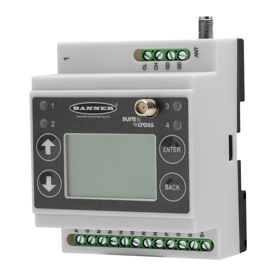
DXM700-Bx Wireless Controller Instruction Manual Cyclical or Change of State write rules to wireless devices or Scheduler local wired Modbus devices with scaling Time/calendar-based events Modbus TCP Client read or write rules for external devices on Holiday skips the network... - Page 7 DXM700-Bx Wireless Controller Instruction Manual DXM Controller base board ISM radio antenna connection Cellular radio antenna connection Housing catch Cellular modem board Processor/base board The DXM Controller base board provides connections for all communications connections, outputs and power/ground. The optional cellular modem is installed in the bottom base board. Attach the antenna cable from the cellular modem to the U.FL connection on the base board.
-
Page 8: Dxm Automation Protocols
Modbus port 502 is used by the DXM for all Modbus TCP/IP client Modbus RTU bus to communicate with locally connect- requests. ed Modbus devices or uses the Banner wireless radio to com- All internal registers are available to the host system concur- municate with remote Modbus devices. -
Page 9: Dxm Modbus Registers
DXM700-Bx Wireless Controller Instruction Manual DXM Controller Modbus overview Processor/Outputs (Base Board) Local Registers ISM Radio (Modbus ID 1) (Modbus ID 199) Local Registers Gateway or MultiHop Ethernet Integer RS-232 User Display (Modbus ID 201) Local Registers Float RS-485 (client) -
Page 10: Dxm Configuration Software
DXM700-Bx Wireless Controller Instruction Manual Modbus Registers for the LCD Board (Modbus ID 201) Modbus Register Color State 1102 : bit 0 LED 1 1103 : bit 0 LED 2 Amber 1104 : bit 0 LED 3 1105: bit 0... -
Page 11: Dimensions
DXM700-Bx Wireless Controller Instruction Manual The wireless network devices are a separate configurable system. Use the DX80 User Configuration Software to configure the internal DX80 wireless Gateway and the attached wireless Nodes. Use the MultiHop Configuration Software if the internal radio is a MultiHop device. - Page 12 Blank page...
-
Page 13: Chapter 2 Quick Start Guide
DXM700-Bx Wireless Controller Instruction Manual Chapter Contents Device Setup ........................................13 Configuration Instructions....................................16 Banner Engineering Corp Limited Warranty..............................19 Chapter 2 Quick Start Guide Device Setup Apply Power to the Controller Follow these instructions to apply 12–30 V DC power to the controller using a wall plug. - Page 14 DXM700-Bx Wireless Controller Instruction Manual Use the arrow keys to select the ISM Radio menu on the LCD and press ENTER. Highlight the Binding menu and press ENTER. Assign the Node address to the Node. ◦ For Nodes without rotary dials: Use the DXM arrow keys to select the Node address to assign to the DX80 Node about to enter binding mode.
-
Page 15: Set A Static Ip Address
DXM700-Bx Wireless Controller Instruction Manual Press BACK on the DXM to exit binding mode for that specific device address. The MultiHop radio's LEDs continue to flash red until the DXM exits binding mode with that MultiHop radio. Label the MultiHop radio with the assigned address number for future reference. -
Page 16: Configuration Instructions
DXM700-Bx Wireless Controller Instruction Manual The changes are saved on the DXM and the new IP address will be used. Use this same procedure to set the subnet mask (SN) and default gateway (GW) to match your network requirements. Your IT department can provide these settings if needed. ... - Page 17 Banner recommends disconnecting the COMM port through the Device menu before turning off power or disconnecting the USB cable. Use Device › Reboot to restart the DXM if needed; the tool automatically disconnects the COMM port, then re- connect it again.
- Page 18 DXM700-Bx Wireless Controller Instruction Manual Modify Multiple Registers screen Enter the Starting register and Ending register. Select the value to change using the drop-down list next to each value. Enter the new value in the field provided. To push register values to the web server, set Cloud Settings to Read.
-
Page 19: Banner Engineering Corp Limited Warranty
Banner Engineering Corp. warrants its products to be free from defects in material and workmanship for one year following the date of shipment. Banner Engineering Corp. will repair or replace, free of charge, any product of its manufacture which, at the time it is returned to the factory, is found to have been defective during the warranty period. - Page 20 DXM700-Bx Wireless Controller Instruction Manual Banner Engineering Corp. reserves the right to change, modify or improve the design of the product without assuming any obligations or liabilities relating to any product previously manufactured by Banner Engineering Corp. Any misuse, abuse, or improper application or installation of this product or use of the product for personal protection applications when the product is identified as not intended for such purposes will void the product warranty.
-
Page 21: Chapter 3 Ism Radio Board (Id 1)
DXM700-Bx Wireless Controller Instruction Manual Chapter Contents MultiHop Radio DIP Switches ................................... 21 Modbus Registers for the MultiHop Radio Board Module ..........................23 DIP Switch Settings for the Performance Gateway Radio Module........................23 Modbus Registers for the Performance Gateway Radio Module ........................24... -
Page 22: Application Mode
DXM700-Bx Wireless Controller Instruction Manual Disabling the serial port disables the ISM radio in the DXM Controller. Selecting Transparent mode causes radio communica- tions to be slower and denies access to device I/O register data. DIP switch settings D1 Switches... -
Page 23: Transmit Power Levels/Frame Size
DXMxxx-xxR3 - DX80 Performance 2.4GHz • DXMxxx-xxR8 - DX80 Performance 900MHz (Australia) IMPORTANT: To adjust the transmit power on the Gateway radio, Banner recommends using the LCD menu (System Conf › ISM Radio › RF CNTRL). July 26, 2023 © Banner Engineering Corp. -
Page 24: Modbus Registers For The Performance Gateway Radio Module
DXM700-Bx Wireless Controller Instruction Manual DIP switch bank 1 and bank 2 Antenna Button Bank 1 Bank 2 DIP switch settings for bank 1 DIP Switch 1 1 Watt (30 dBm, 900 MHz models only) (default configuration) 250 mW (24 dBm, 900 MHz models only), DX80 compatibility mode... -
Page 25: Alternative Modbus Register Organization
DXM700-Bx Wireless Controller Instruction Manual Continued from page 24 I/O Point Gateway Node 1 Node 2 Node 3 Node 4 Node 5 Node 6 Node 7 Access all wireless network registers by reading Modbus ID 1 DX80 Device Modbus ID... - Page 26 DXM700-Bx Wireless Controller Instruction Manual When networks use similar Nodes to gather data using the same I/O registers for each Node, discrete data from multiple Nodes can be bit packed into a single register on the Gateway. The bit-packed data is arranged by I/O point starting at Mod- bus register 6601.
- Page 27 DXM700-Bx Wireless Controller Instruction Manual Software). For example, a least significant bit of one (1) indicates the analog value is above the selected threshold value. A least significant bit of zero (0) indicates the analog value is below the threshold value.
- Page 28 Blank page...
- Page 29 DXM700-Bx Wireless Controller Instruction Manual Chapter Contents DIP Switch Settings for the Base Board ................................30 Ethernet ..........................................30 USB ..........................................30 Internal Local Registers (ID 199) for the DXM700, DXM1000, and DXM1200 ....................31 Applying Power to the DXM Controller ................................34 Connecting the Communication Pins ................................
-
Page 30: Dip Switch Settings For The Base Board
DXM700-Bx Wireless Controller Instruction Manual LED Operation Cellular Modem Connection The PCB LED flashes to indicate the processor board is run- Install the cellular modem onto the board with the cellular ning. modem's U.FL connector on the right. The antenna cable will go between the cellular U.FL connector and the board U.FL... -
Page 31: Internal Local Registers (Id 199) For The Dxm700, Dxm1000, And Dxm1200
DXM700-Bx Wireless Controller Instruction Manual Internal Local Registers (ID 199) for the DXM700, DXM1000, and DXM1200 The main storage elements for the DXM Controller are its local registers, which can store 4-byte values that result from regis- ter mapping, action rules, or ScriptBasic commands. - Page 32 DXM700-Bx Wireless Controller Instruction Manual Modbus registers for virtual registers Registers Definition 10001 GPS latitude direction (N, S, E, W) 10002 GPS latitude GPS Coordinate Data if the DXM is configured to read an external GPS unit. 10003 GPS longitude direction (N, S, E, W)
- Page 33 DXM700-Bx Wireless Controller Instruction Manual Continued from page 32 Registers Definition 10112 Passthrough success streak 10113 Number of 43 buffer successes 10114 Number of 43 buffer timeouts DX80 Gateway automatic messaging buffer statistics 10115 Number of 43 buffer errors 10116...
-
Page 34: Applying Power To The Dxm Controller
DXM700-Bx Wireless Controller Instruction Manual Continued from page 33 Reset Code Definition Unknown General Brownout Watchdog User Software Return from backup mode Applying Power to the DXM Controller Apply power to the DXM Controller using 12 to 30 V DC. -
Page 35: Set The Client And Server Port Parameters
DXM700-Bx Wireless Controller Instruction Manual Set the Client and Server Port Parameters The basic communications parameters for the RS-485 ports are set in the DXM Configuration Software and are saved in the XML configuration file. Settings > General screen In the DXM Configuration Software, go to the Settings › General screen. -
Page 36: Modbus I/O Registers For The Base Board
DXM700-Bx Wireless Controller Instruction Manual Refer to the Modbus Registers section for more descriptions of each Modbus register on the DXM Controller. Modbus I/O Registers for the Base Board Modbus Registers for the Base Board Outputs (Modbus ID 203) Modbus Register... -
Page 37: Chapter 5 Cellular Modem Boards
Follow these basic steps, as detailed in this document, to activate the cellular capabilities of your DXM Controller. Purchase a cellular modem kit from Banner Engineering Corp. Install the cellular modem, connect the antenna cable, and connect the cellular antenna. - Page 38 SIM provider. For additional information, refer to the Banner Cloud Data Services support center (support.bannercds.com). The support center includes video tutorials, product documentation, technical notes, and links to download configuration software. IMPORTANT: Only the DXM100 and DXM150 models in conjunction with an SXI-LTE-001 (obsolete) cel- lular modem can offer SMS/text messaging capabilities directly from the device.
- Page 39 DXM700-Bx Wireless Controller Instruction Manual Installing the cellular modem SIM cards come in a credit card sized carrier. Carefully snap it out of the carrier. Make note of the IMEI number of the cellular modem and the ICCID number of the SIM card.
- Page 40 DXM700-Bx Wireless Controller Instruction Manual Install the Cellular Modem (DXM1200 Models) Follow these steps to install the cellular modem and antenna cable. IMPORTANT: • Electrostatic discharge (ESD) sensitive device • ESD can damage the device. Damage from inappropriate handling is not covered by warranty.
- Page 41 41. However, there may be regions that are not covered by the provided SIM card. In this case, a local SIM card must be activated and operated with this device to acquire connectivity services. Work with the local Banner technical support person to identify and purchase machine-to-machine (M2M) (data plan only) SIM cards in 3FF 'micro' form factor. Typical monthly data use will be 20-50 MB per month. When choosing a plan, pay close attention to data rates.
- Page 42 For regions outside of North America—Select SXI-CATM1WW-001 and set the APN to m2m.tele2.com when using the SIM card provided with the kit from Banner Engineering. When using a local roaming SIM, please use the APN as suggested by your cellular connectivity (SIM) provider.
- Page 43 Obtaining LTE service outside of the Banner Cellular Data Plans—Customers have the option of securing a data plan for the Verizon network themselves without using the Banner cellular data portal (celldata.bannercds.com). Suitable plans would include those available from Verizon directly or from a Mobile Virtual Network Operator (MVNO) licensed to resell Verizon network data plans. (The SXI-LTE-001 or SXI-CATM1VZW-001 will not function on AT&T, T-Mobile, or Sprint networks.) ...
- Page 44 Blank page...
-
Page 45: Registers
DXM700-Bx Wireless Controller Instruction Manual Chapter Contents Registers .......................................... 45 Push ..........................................46 ISM Radio ......................................... 46 I/O Board ......................................... 46 System Config ........................................47 System Info ........................................49 Display Lock ........................................50 Modbus Registers for the LCD Board (Modbus ID 201) ........................... 50... -
Page 46: Push
DXM700-Bx Wireless Controller Instruction Manual Read allows the register to be displayed and Write or Read/Write allows the register value to be changed using the LCD. The Units and Scaling parameters are optional and affect the LCD. Push The Push menu displays information about the last data sent to the Webserver. -
Page 47: System Config
DXM700-Bx Wireless Controller Instruction Manual System Config Use the System Config menu to set DXM Controller system parameters. System Config menu ISM Radio DX80 ID: x New ISM Modbus ID: x System Config Auto Detect Radio ID: 1 Advanced Options... -
Page 48: Ethernet
DXM700-Bx Wireless Controller Instruction Manual Binding #—This parameter allows the user to define the Binding code within the ISM radio. Typically, you will not have to ad- just this number unless you are replacing an existing Gateway or client radio. -
Page 49: System Info
DXM700-Bx Wireless Controller Instruction Manual System Info Various DXM system settings are shown in this menu. The Push, Ethernet, and Cell parameters are helpful for debugging network connections. This is a read-only menu. System Info menu Date: System Info Controller ↑... -
Page 50: Display Lock
DXM700-Bx Wireless Controller Instruction Manual Display Lock Display Lock protects the DXM LCD menu system from being used until the proper pass code is entered. Display Lock menu Display Lock Enter password ↑ ↓ >> x to change the value... -
Page 51: Chapter 7 Working With Modbus Devices
DXM700-Bx Wireless Controller Instruction Manual Chapter Contents Assigning Modbus IDs ...................................... 52 Modbus Operation ......................................52 Wireless and Wired Devices .................................... 52 Modbus Communication Timeouts ..................................53 Modbus TCP Client ......................................54 Chapter 7 Working with Modbus Devices The DXM Controller has two physical RS-485 connections using Modbus RTU protocol. -
Page 52: Assigning Modbus Ids
DXM700-Bx Wireless Controller Instruction Manual DXM Internal Modbus IDs (factory default) Modbus ID Device DX80 Performance Gateway or MultiHop ISM Radio—MultiHop wireless devices connected to the internal MultiHop radio should be assigned Modbus addresses starting at 11. Local Registers—Internal storage registers of the DXM Controller Base Board Outputs—Outputs of the DXM Controller. -
Page 53: Modbus Communication Timeouts
DXM700-Bx Wireless Controller Instruction Manual Continued from page 52 Modbus ID Description 2–10 Server addresses available for directly connected Modbus server devices to the client RS485 port (M+ , M-) Allocated for wireless MultiHop radio network devices. If there is not an internal MultiHop in the DXM Controller, these server ad- 11–60... -
Page 54: Calculating The Communication Timeout For 10-30 Vdc Multihop Radios
DXM700-Bx Wireless Controller Instruction Manual Client to Repeater Send time = (9 × 0.04 sec) + (8 retry wait × 0.04 sec) = 1 second Repeater to Client Send time = (9 × 0.04 sec) + (8 retry wait × 0.04 sec) = 1 second... -
Page 55: Chapter 8 Configuration Instructions
DXM700-Bx Wireless Controller Instruction Manual Chapter Contents Scheduler .......................................... 55 Authentication Setup ......................................56 Register Flow and Configuration ..................................58 EtherNet/IP™ Configuration....................................59 Define the Network Interface Settings................................60 Ethernet and Cellular Push Retries ................................... 61 Chapter 8 Configuration Instructions... -
Page 56: Create A One-Time Event
DXM700-Bx Wireless Controller Instruction Manual Register updates can be changed up to two times per day for each rule. Each rule can be set for any number of days in the week by clicking the buttons M, T, W, Th, F, S, or Su. If two register changes are defined for a day, define the start time to be before the end time. Select End Value to enable the second event in a 24 hour period. To span across two days (crossing the midnight boundary), set the start value in the first day, without selecting End Value. Use the next day to create the final register state. ... -
Page 57: Set The Controller To Use Authentication
DXM700-Bx Wireless Controller Instruction Manual Set the Controller to use Authentication The DXM Controller can be configured to send login and password credentials for every HTTP packet sent to the webserver. This provides another layer of security for the webserver data. -
Page 58: Register Flow And Configuration
DXM700-Bx Wireless Controller Instruction Manual Register Flow and Configuration The DXM Controller register data flow goes through the Local Registers, which are data storage elements that reside within the processor. Using the DXM Configuration Software, the controller can be programmed to move register data from the Lo- cal Register pool to remote devices, the internal radio, the I/O base (if applicable), or the display. -
Page 59: Uploading Or Downloading Configuration Files
This allows the user to maximize the use of the EtherNet/IP buffer to 28 devices. EDS (Electronic Data Sheet) files allow users of the EtherNet/IP protocol to easily add a Banner DXM device to the PLC. Download the EDS files from the Banner website. -
Page 60: Define The Network Interface Settings
DXM700-Bx Wireless Controller Instruction Manual Continued from page 59 EIP Assembly Instance 112 (16-bit) DXM Local Registers 5566 5566 7788 7788 9900 9900 Data from the DXM Controller local registers is sent to the EIP controller using assembly instance 100. Each local register in the DXM Controller defined as EIP DXM ›... -
Page 61: Configure Your Cellular Connection
On the Settings › Cellular screen, select your cellular modem from the drop-down list. Set the APN. ◦ If you are using a Banner 4G LTE-M Verizon Module (ME910C1), set the APN to vzwinternet. ◦ If you are using a Banner 4G LTE AT&T Module (ME910C1), set the APN to iot0119.com.attz. -
Page 62: Cellular Push Retries
DXM700-Bx Wireless Controller Instruction Manual Using SSL on Ethernet will have no retries, but will save each failed attempt to the micro SD card until 10 failed rounds. At this time, the register data packet is archived. Cellular Push Retries In a cellular-connected system there are no retries. -
Page 63: Chapter 9 Profinet
DXM700-Bx Wireless Controller Instruction Manual Chapter Contents General Station Description Markup Language File ............................63 DXM PROFINET IO Data Model ..................................63 Configure the DXM Controller for a PROFINET IO Connection ........................63 Slots and Modules for the DXMR90-X1, DXM700, DXM1000, and DXM1200 PROFINET ................64 Example Configuration ...................................... -
Page 64: Slots And Modules For The Dxmr90-X1, Dxm700, Dxm1000, And Dxm1200 Profinet
DXM700-Bx Wireless Controller Instruction Manual Status indicator bar ◦ If the Application Status indicator is red, close and restart the DXM Configuration Tool, unplug and re-plug in the cable and reconnect the DXM to the software. ◦ If the Application Status indicator is green, the file upload is complete. -
Page 65: Example Configuration
DXM700-Bx Wireless Controller Instruction Manual Slots 4 through 6 Module Notes Input Float 512 Allowed in slots 4-6, Module Identifier= 0x34 Input Float 256 Allowed in slots 4-6, Module Identifier= 0x35 Input Float 128 Allowed in slots 4-6, Module Identifier= 0x36... - Page 66 DXM700-Bx Wireless Controller Instruction Manual Devices and networks screen Click Configure networks. Configure networks screen Click Options and select Manage general station description file (GSD). The Install general station decription file window opens. Click the More options (...) icon to the right of the Source path field and browse to the location the DXM GSD file was downloaded to.
-
Page 67: Change The Device Ip Address
Hardware catalog The system installs the DXM GSD file and places it in the Hardware catalog. In the example, the DXM GSD file is lo- cated under Other field devices › PROFINET IO › Banner Engineering Corp. › Banner. If the DXM GSD file does not install properly, save the log and contact Banner Engineering Corp. ... - Page 68 DXM700-Bx Wireless Controller Instruction Manual Select PROFINET Interface › Ethernet addresses. Ethernet addresses Select Set IP address in the project. Enter the IP address. Right-click on the device icon and select Online & diagnostics. Online & diagnostics menu and screen The Online &...
-
Page 69: Change The Device Name
DXM700-Bx Wireless Controller Instruction Manual The IP address for the device is updated. Click Assign IP address to complete the step. This step is completed for every device. By default, each DXM shipped from the factory is assigned the IP address 192.168.0.1. Immediately after the PROFINET protocol is enabled, the DXM has an IP address of 0.0.0.0. We recommend using the TIA Portal to give the DXM an IP address so that the address is saved in the unit. - Page 70 Blank page...
-
Page 71: Chapter 10 Accessories
DXM700-Bx Wireless Controller Instruction Manual Chapter Contents Chapter 10 Accessories For a complete list of all the accessories for the Sure Cross wireless product line, please download the Accessories List (p/ n b_3147091). Misc Accessories Cordsets BWA-CG.5-3X5.6-10—Cable Gland Pack: 1/2-inch NPT, Cordgrip for 3 MQDC1-506—5-pin M12, straight, single-ended, 6 ft... - Page 72 Blank page...
-
Page 73: File System And Archive Process
Chapter Contents File System and Archive Process ..................................73 Update Your DXM Processor Firmware Using the DXM Configuration Software ..................... 74 Clear the Password on DXM700-Bx, DXM1000-Bx, or DXM1200-Bx Models ....................74 DXM700 Documentation ....................................74 DXM Support Policy ......................................75 Specifications ........................................ -
Page 74: Update Your Dxm Processor Firmware Using The Dxm Configuration Software
After the file load is completed, the DXM restarts and loads the new firmware file. It takes about 2 minutes to complete the programming process. The device reboots when finished. Verify the firmware has been updated, under Settings › Gener al › Device Information. Clear the Password on DXM700-Bx, DXM1000-Bx, or DXM1200-Bx Models By default, the DXM Controllers do not require a password to load a configuration file. If a password is defined, the password must be entered before uploading a configuration file. -
Page 75: Dxm Support Policy
Banner website. Customers with critical update requirements will get access to pre-released firmware from the factory. Website Information The Banner website is the main method of disseminating DXM information to customers. The data found on the website in- clude: •... -
Page 76: Environmental Specifications For The Dxm700
DXM700-Bx Wireless Controller Instruction Manual antenna gain, environment, and line of sight. Always verify 900 MHz Compliance (RM1809 Radio Module) your wireless network's range by performing a Site Survey. Radio module is indicated by the product label marking Radio Transmit Power (900 MHz, 1 Watt radios) - Page 77 DXM700-Bx Wireless Controller Instruction Manual Power Connections Discrete Outputs DXM700-B1: Wiring terminals Four, PNP/Sourcing DXM700-B2: Barrel jack Update Rate: 125 milliseconds ON Condition: Supply minus 2 V Construction Polycarbonate; DIN rail mount option OFF Condition: Less than 2 V Communication Protocols...
-
Page 78: Contact Us
All measurements are listed in millimeters [inches], unless noted otherwise. Contact Us Banner Engineering Corp. headquarters is located at: 9714 Tenth Avenue North | Minneapolis, MN 55441, USA | Phone: + 1 888 373 6767 For worldwide locations and local representatives, visit www.bannerengineering.com. -
Page 79: Fcc And Ised Certification, 900 Mhz, 1 Watt Radios
DXM700-Bx Wireless Controller Instruction Manual This device may not cause interference. This device must accept any interference, including interference that may cause undesired operation of the device. Cet appareil contient des émetteurs/récepteurs exemptés de licence conformes à la norme Innovation, Sciences, et Développement économique Canada. -
Page 80: Fcc And Ised Certification, 2.4Ghz
DXM700-Bx Wireless Controller Instruction Manual Certified Antennas for 900 MHz 1 Watt 900 MHz Radio Mod Minimum Required Ca Model Number Antenna Type Maximum Gain Impedance ble/Connector Loss - Integral Antenna RM1809 Unity gain 0 BWA9O1x Omni, 1/4 wave dipole RM1809 ≤2 dBi 50 Ω ... -
Page 81: Fcc And Ised Approved Antennas
DXM700-Bx Wireless Controller Instruction Manual FCC and ISED Approved Antennas WARNING: Antenna(s) used for this transmitter must be installed to provide a separation distance of at least 20 cm from all persons. AVERTISSEMENT : Les antennes utilisées pour cet émetteur doivent être installées de manière à assurer une distance de séparation d'au moins 20 cm de toutes les personnes. ... -
Page 82: Warnings
International certifications are not inclusive of all Banner Engineering Sure Cross® Radios. For product-specific certifica- tions, contact a local Banner Engineering representative. Mexican Importer Banner Engineering de Mèxico, S. de R.L. de C.V. | David Alfaro Siqueiros 103 Piso 2 Valle oriente | San Pedro Garza Garcia Nuevo Leòn, C. P. 66269 81 8363.2714 ANATEL Este equipamento não tem direito à... - Page 83 This device has been designed to operate with the antennas listed on Banner Engineering’s website and having a maximum gain of 9 dBm. Antennas not included in this list or having a gain greater than 9 dBm are strictly prohibited for use with this device.
-
Page 84: Document Information
DXM700-Bx Wireless Controller Instruction Manual Banner Engineering Corp. reserves the right to change, modify or improve the design of the product without assuming any obligations or liabilities relating to any product previously manufactured by Banner Engineering Corp. Any misuse, abuse, or improper application or installation of this product or use of the product for personal protection applications when the product is identified as not intended for such purposes will void the product warranty. - Page 85 LinkedIn Twitter Facebook © 2023. All rights reserved. www.bannerengineering.com...
Need help?
Do you have a question about the DXM700-Bx and is the answer not in the manual?
Questions and answers