
Related Manuals for Banner DXM1200-X2


Summary of Contents for Banner DXM1200-X2
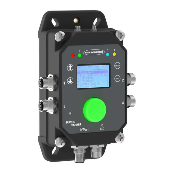
- Page 1 DXM1200-X2 Controller Instruction Manual Original Instructions p/n: 239172 Rev. A February 02, 2024 © Banner Engineering Corp. All rights reserved.
-
Page 2: Table Of Contents
LCD Contrast ......................................48 Reset........................................48 System Info........................................48 Display Lock ........................................ 49 DXM1200-X2 Modbus Registers for the LCD (Modbus ID 201)........................49 Chapter 7 Working with Modbus Devices Assigning Modbus IDs....................................52 Modbus Operation ....................................... 52 Wireless and Wired Devices..................................52 ... - Page 3 Radio Specifications for Performance and MultiHop (500 mW) ......................76 Radio Specifications for Performance and MultiHop (1 Watt) ......................76 RS-485 Communication Specifications ..............................77 DXM1200-X2 Specifications ................................. 77 Environmental Specifications (DXM1200) ............................77 DXM1200-X2 Dimensions ..................................78 FCC and ISED Certification for 900 MHz 1 W and 500 mW Radios ......................78 FCC Notices ........................................
- Page 4 Warnings........................................81 Banner Engineering Corp Limited Warranty..............................82 Document Information ....................................82 ...
-
Page 5: Chapter 1 Dxm1200-X2 System Overview
DXM1200-X2 System Overview Banner's DXM Logic Controller consolidates data from multiple sources using serial Modbus and local wireless networks to provide data processing as well as accessibility for host systems as a platform for the Industrial Internet of Things (IIoT). - Page 6 Connect directly to any PLC and/or SCADA system for easy integration into existing control or monitoring systems. Banner Industrial Wireless radios have two types of networks that can be used for creating applications and solving problems.
-
Page 7: Dxm1200-X2 Models Key
DXM Hardware Configuration Overview The DXM1200-X2 Wireless Controller can have multiple configurations. The DXM Controller will have a model number label on the housing. Use the model number and model table above to identify which boards are included in the controller. -
Page 8: Dxm1200 Automation Protocols
Controller uses the client Modbus RTU bus to communicate individual local register configurations can be set with the with locally connected Modbus devices or uses the Banner Protocol Conversion field in the DXM Configuration Software. wireless radio to communicate with remote Modbus devices. -
Page 9: Dxm1200-X2 Modbus Registers
Processor Controller Cellular Modem Modbus Data Traffic Control DXM1200-X2 Modbus Registers The DXM1200-X2 Wireless Controller may have up to three internal Modbus server devices: DXM1200-X2 internal Modbus IDs (factory default) Modbus ID Device DX80 Performance Gateway or MultiHop ISM Radio—MultiHop wireless devices connected to the internal MultiHop radio should be assigned Modbus IDs starting at 11. -
Page 10: Dxm1200-X2 Dimensions
1)—See "Modbus Registers for the MultiHop Radio Board Module" on page "Modbus Registers for the Performance Gateway Radio Module" on page DXM1200-X2 Dimensions All measurements are listed in millimeters, unless noted otherwise. DXM1200-X2 dimensions February 02, 2024 © Banner Engineering Corp. All rights reserved. -
Page 11: Chapter 2 Quick Start Guide
Configuration Instructions....................................14 Chapter 2 Quick Start Guide Device Setup Apply Power to the DXM1200-X2 Controller Use the following wiring diagrams to wire power and communication to the DXM Controller. Connecting power to the communication pins will cause permanent damage. Follow the steps to power your DXM using a wall plug. Equipment used: • DXM1200-X2 •... -
Page 12: Binding And Conducting A Site Survey With The Ism Radio
The Node LEDs continue to flash red until the DXM exits binding mode with that Node address. Repeat these steps for as many DX80 Nodes as are needed for your network. February 02, 2024 © Banner Engineering Corp. All rights reserved. - Page 13 Missed packets were not received. When you are finished running the Site Survey, press Back twice to return to the main menu and exit site survey mode. February 02, 2024 © Banner Engineering Corp. All rights reserved.
-
Page 14: Set A Static Ip Address
If you find poor signal quality, common solutions include moving the DXM to a more central location relative to the Nodes or using higher-gain antennas on the DXM. Contact your local Banner Engineering representative for assistance. Set a Static IP Address Change the IP address of the DXM to connect to a local area network, Modbus TCP/IP host controller, or EtherNet/IP host controller. -
Page 15: Configuring The Dxm1200-X2 Controller
On the computer, download the DXM Configuration Software v4 from the Banner Engineering website and install it. On the DXM: Apply power to the DXM. Connect the DXM Controller to the computer with an M12 to RJ-45 cable or skip if the DXM is connected to the same network as the computer. -
Page 16: Configuration Example: Reading Registers On A Modbus Server Device
This example screen shows a read rule created to read six registers (address 1 through 6), from Modbus ID 4. The results are stored in the Local Registers 1 through 6. February 02, 2024 © Banner Engineering Corp. All rights reserved. - Page 17 This example creates a read rule to read six registers (1 through 6), from the radio (port 5) at Modbus ID 1. The results are stored in the Local Registers 1 through 6. Define the port settings to be compatible with the connected devices. Go to the Register Mapping › RTU › RTU Configuration screen. February 02, 2024 © Banner Engineering Corp. All rights reserved.
- Page 18 If necessary, select the error condition. For this example, if the read function fails after three attempts, the read rule writes 12345 to the DXM local registers. Notice the list of local register names this read rule is using. February 02, 2024 © Banner Engineering Corp. All rights reserved.
-
Page 19: Save And Upload The Configuration File
If the Application Status indicator is gray and the green status bar is in motion, the file transfer is in progress. After the file transfer is complete, the device reboots and begins running the new configuration. February 02, 2024 © Banner Engineering Corp. All rights reserved. - Page 20 ...
-
Page 21: Chapter 3 Ism Radio Board (Id 1)
Serial line baud rate 38400 OR 32 receiver slots Serial line baud rate 9600 OR 128 receiver slots Serial line baud rate Custom OR 4 receiver slots Parity: None OFF* OFF* Parity: Even Continued on page 22 February 02, 2024 © Banner Engineering Corp. All rights reserved. -
Page 22: Application Mode
For battery-powered devices, increasing the throughput decreases battery life. IMPORTANT: Prior to date code 15341 and radio firmware version 3.6, the frame timing was 40 ms (OFF) or 20 ms (ON). February 02, 2024 © Banner Engineering Corp. All rights reserved. -
Page 23: Modbus Registers For The Multihop Radio Board Module
• DXMxxx-xxR3 - DX80 Performance 2.4GHz • DXMxxx-xxR8 - DX80 Performance 900MHz (Australia) IMPORTANT: To adjust the transmit power on the Gateway radio, Banner recommends using the LCD menu (System Conf › ISM Radio › RF CNTRL). Button DIP Switch DIP Switch Bank 1... -
Page 24: Alternative Modbus Register Organization
Modbus Register Address (Decimal) Inputs and Outputs, in order by device 2201 through 4784 Discrete Bit Packed (Status, Discrete Inputs, Discrete Outputs) 6601 through 6753 Analog Inputs (1–8) and Analog Outputs (1–8) 6801 through 9098 February 02, 2024 © Banner Engineering Corp. All rights reserved. - Page 25 Node 46 Node 45 Node 44 Node 43 Node 42 Node 41 Node 40 Node 39 Node 38 Node 37 Node 36 Node 35 Node 34 Node 33 Node 32 February 02, 2024 © Banner Engineering Corp. All rights reserved.
- Page 26 6802 Input 1 for Node 1 8002 Output 1 for Node 1 6803 Input 1 for Node 2 8003 Output 1 for Node 2 Continued on page 27 February 02, 2024 © Banner Engineering Corp. All rights reserved.
- Page 27 For example, 6801 contains the input 1 value for the Gateway, 6802 contains the input 1 value for Node 1, and 6848 contains the input 1 value for Node 47. February 02, 2024 © Banner Engineering Corp. All rights reserved.
- Page 28 ...
- Page 29 DIP Switch Settings for the Base Board................................30 Ethernet ..........................................31 USB ............................................ 31 Internal Local Registers (ID 199) for the DXM700, DXM1000, and DXM1200 ....................31 DXM1200-X2 as a Modbus RTU Client................................34 Chapter 4 DXM1200 Processor Connections...
-
Page 30: Dip Switch Settings For The Base Board
XML Tool operations. configuration file. After the device is running, a new XML file can be loaded using the DXM configuration tool. The factory default position is OFF. February 02, 2024 © Banner Engineering Corp. All rights reserved. -
Page 31: Ethernet
1001–5000 Floating point Floating point registers, local data registers 5001–7000 32-bit integer Local data registers 7001–8000 32-bit non-volatile integer Data flash, non-volatile > 10000 Read-only virtual registers, system-level data February 02, 2024 © Banner Engineering Corp. All rights reserved. - Page 32 1 = Attempt complete 2 = Attempt aborted Cellular signal strength. Value range: 0–31 0 = –113 dBm or less 1 = –111 dBm 10039–10040 Cellular Strength, BER 2–30 = –109 dBm through –53 dBm in 2 dBm steps 31 = –51 dBm or greater 99 = not known or not detectable; BER not used Continued on page 33 February 02, 2024 © Banner Engineering Corp. All rights reserved.
- Page 33 2x013 Socket x resolvers (reserved) 2x015–2x020 Reserved 2x021 Socket x Rule 0 transmits 2x023 Socket x Rule 0 receives 2x025 Socket x Rule 0 timeouts Continued on page 34 February 02, 2024 © Banner Engineering Corp. All rights reserved.
-
Page 34: Dxm1200-X2 As A Modbus Rtu Client
Software Return from backup mode DXM1200-X2 as a Modbus RTU Client The DXM Controller can be a Modbus RTU client device to other server devices. The DXM Controller uses the primary RS-485 port as a Modbus RTU client to control external server devices. All wired devices connected to the client RS-485 port must be server devices. -
Page 35: Set The Client And Server Port Parameters
The Internal Server ID is the Modbus ID that an external Modbus Client will access to read/write to the local registers on the DXM Controller. Slave Port 0 Settings February 02, 2024 © Banner Engineering Corp. All rights reserved. - Page 36 ...
-
Page 37: Chapter 5 Cellular Modem Boards
Follow these basic steps, as detailed in this document, to activate the cellular capabilities of your DXM Controller. Purchase a cellular modem kit from Banner Engineering Corp. Install the cellular modem, connect the antenna cable, and connect the cellular antenna. - Page 38 SIM provider. For additional information, refer to the Banner Cloud Data Services support center (support.bannercds.com). The support center includes video tutorials, product documentation, technical notes, and links to download configuration software. IMPORTANT: Only the DXM100 and DXM150 models in conjunction with an SXI-LTE-001 (obsolete) cellular modem can offer SMS/text messaging capabilities directly from the device.
- Page 39 Use proper handling procedures to prevent ESD damage. Proper handling procedures include leaving devices in their anti-static packaging until ready for use; wearing anti-static wrist straps; and assembling units on a grounded, static-dissipative surface. February 02, 2024 © Banner Engineering Corp. All rights reserved.
- Page 40 Attach the antenna cable between the cellular modem board to the base board. The antenna cable uses the top antenna connection. Activate a 4G LTE CAT M1 Cellular Plan Activate a cellular plan for your DXM Controller using the Banner Cloud Data Services website. Go to celldata.bannercds.com to purchase cellular data plans.
- Page 41 SIM card. In this case, a local SIM card must be activated and operated with this device to acquire connectivity services. Work with the local Banner technical support person to identify and purchase machine-to-machine (M2M) (data plan only) SIM cards in 3FF 'micro' form factor.
- Page 42 LCD menu, select Push › Trigger Data Push. Obtaining LTE service outside of the Banner Cellular Data Plans—Customers have the option of securing a data plan for the Verizon network themselves without using the Banner cellular data portal (celldata.bannercds.com). Suitable plans would ...
- Page 43 SENSX002) and give the IMEI number (found on the cellular modem) to the plan provider. To use the SIM card that comes with the cellular modem kit, give the SIM card number to the provider. The required SIM card form factor is 3FF - Micro. Document title: Install and Activate a Cellular Modem Part number: 205026 Revision: G Original Instructions © Banner Engineering Corp. All rights reserved. February 02, 2024 © Banner Engineering Corp. All rights reserved.
- Page 44 ...
-
Page 45: Chapter 6 Lcd And Menu System
ISM Radio........................................... 46 System Config ........................................47 System Info ........................................48 Display Lock ........................................49 DXM1200-X2 Modbus Registers for the LCD (Modbus ID 201) ........................49 Chapter 6 LCD and Menu System The LCD has four user-defined LED indicators, four control buttons, and an LCD. The four buttons control the menu system on the LCD menu. -
Page 46: Push
"Binding and Conducting a Site Survey with the ISM Radio" on page 12. For more information on binding a particular device, refer to the individual datasheet. Site Survey—After creating a wireless network using the binding process, run a site survey on each device to see the link quality. See "Conduct a Site Survey from the DXM" on page February 02, 2024 © Banner Engineering Corp. All rights reserved. -
Page 47: System Config
DXM Controller will not be able to run Binding or Site Survey through the LCD menu. Max Node Count—Defines the maximum number of devices for the DX80 wireless network. Binding #—This parameter allows the user to define the Binding code within the ISM radio. Typically, you will not have to adjust this number unless you are replacing an existing Gateway or client radio. February 02, 2024 © Banner Engineering Corp. All rights reserved. -
Page 48: Ethernet
Shows the cellular MEID number (Mobil Equipment Identifier), Cell MDN (Mobil Device Number), version, signal, firewall setting, and firewall mask. Some of these parameters are not visible until the cellular network is accessed. February 02, 2024 © Banner Engineering Corp. All rights reserved. -
Page 49: Display Lock
The display lock feature uses the configuration software to set a passcode within the DXM. A valid passcode is 1 to 9 digits long and uses numbers 0 through 9. For example, 1234 or 209384754. DXM1200-X2 Modbus Registers for the LCD (Modbus ID 201) Control the four bi-color LEDs using the display's Modbus registers. Using write maps or ScriptBasic, write the Modbus registers shown below with 0 (off) or 1 (on). - Page 50 DXM1200-X2 Controller Instruction Manual Turning both groups on for the same color increases the intensity of the light. For example, setting registers 1107 and 1110 to 1 doubles the number of LEDs turned on, effectively doubling the intensity of the blue color. February 02, 2024 © Banner Engineering Corp. All rights reserved.
-
Page 51: Chapter 7 Working With Modbus Devices
There are server IDs that are reserved for internal devices in the DXM Controller. DXM internal Modbus IDs (factory default) Modbus ID Device DX80 Performance Gateway or MultiHop ISM Radio—MultiHop wireless devices connected to the internal MultiHop radio 1 should be assigned Modbus IDs starting at 11. 199 Local Registers—Internal storage registers of the DXM Controller 201 LCD—The user has access to the LED indicators on the DXM Controller. February 02, 2024 © Banner Engineering Corp. All rights reserved. -
Page 52: Assigning Modbus Ids
Available to users for direct-connected Modbus server devices or the expansion of the wireless network server IDs to go past 50 61–198 wireless devices. Allocated for internal Local Register Allocated for the LCD display board, the user can read/write LEDs. February 02, 2024 © Banner Engineering Corp. All rights reserved. -
Page 53: Modbus Communication Timeouts
For each repeater added to the network, increase the timeout parameter 2 seconds. For a client radio to a 10–30 V DC powered server radio (no repeaters): Client to Server Send time = (9 × 0.04 sec) + (8 retry wait × 0.04 sec) = 1 second February 02, 2024 © Banner Engineering Corp. All rights reserved. -
Page 54: Adjusting The Receive Slots And Retry Count Parameters
Modbus TCP server devices to read Modbus register data over Ethernet. Use the DXM Configuration Software to define and configure Modbus TCP client communications with other Modbus TCP servers. February 02, 2024 © Banner Engineering Corp. All rights reserved. -
Page 55: Scheduler
Use the drop-down list to select the type of Start at time: a specific time or a relative time. Enter the starting time. Enter the end time and end value for the local register. February 02, 2024 © Banner Engineering Corp. All rights reserved. -
Page 56: Create A One-Time Event
The DXM Controller has three areas that can be configured to require login and password authentication. • Webserver/ Cloud Services Authentication • Mail Server Authentication • DXM Configuration Authentication The webserver and mail server authentication depends upon the service provider. February 02, 2024 © Banner Engineering Corp. All rights reserved. -
Page 57: Set The Controller To Use Authentication
Remove the Admin Password To change or remove an admin password, you are required to enter the current password and the DXM Controller must be connected to the PC. February 02, 2024 © Banner Engineering Corp. All rights reserved. -
Page 58: Register Flow And Configuration
To expand the number of devices going to Ethernet/IP, change the Devices in system parameter in the DX80 Gateway (default setting is 8) to 32. To change this value: Launch the the DX80 Configuration Software. EttherNet/IP is a trademark of Rockwell Automation. February 02, 2024 © Banner Engineering Corp. All rights reserved. -
Page 59: Configuring The Host Plc
This allows the user to maximize the use of the EtherNet/IP buffer to 28 devices. EDS (Electronic Data Sheet) files allow users of the EtherNet/IP protocol to easily add a Banner DXM device to the PLC. Download the EDS files from the Banner website. -
Page 60: Define The Network Interface Settings
DNS settings are not typically required. The DXM Controller uses a public service to resolve Domain names, but if the network connection does not have Internet access, the DNS settings may be required. Settings > Ethernet screen February 02, 2024 © Banner Engineering Corp. All rights reserved. -
Page 61: Configure Your Cellular Connection
Set the APN. ◦ If you are using a Banner 4G LTE-M Verizon Module (ME910C1), set the APN to vzwinternet. ◦ If you are using a Banner 4G LTE AT&T Module (ME910C1), set the APN to iot0119.com.attz. ◦ If you are using a Banner 4G LTE-M/NB-IoT Worldwide Module (ME910G1), set the APN to m2m.tele2.com. ◦ If you are using a third-party SIM card, the APN, APN Username, and Password must be provided by the cellular service provider. - Page 62 ...
-
Page 63: Chapter 9 Profinet
Save the XML configuration file to your hard drive by going to the File › Save As menu. Go to the DXM › Send XML Configuration to DXM menu. February 02, 2024 © Banner Engineering Corp. All rights reserved. -
Page 64: Slots And Modules For The Dxmr90-X1, Dxm700, Dxm1000, And Dxm1200 Profinet
Input Integer 64 Allowed in slots 1-3, Module Identifier= 0x33 Slots 4 through 6 Module Notes Input Float 512 Allowed in slots 4-6, Module Identifier= 0x34 Continued on page 65 February 02, 2024 © Banner Engineering Corp. All rights reserved. -
Page 65: Install The Gsd File
Download the GSD file from www.bannerengineering.com. Launch the Siemens TIA Portal (v14) software. Click Open existing project. Select a project and open it. After the project is uploaded, click Devices & networks. February 02, 2024 © Banner Engineering Corp. All rights reserved. - Page 66 Click the More options (...) icon to the right of the Source path field and browse to the location the DXM GSD file was downloaded to. Select the DXM GSD file. Click Install. February 02, 2024 © Banner Engineering Corp. All rights reserved.
-
Page 67: Change The Device Ip Address
The system installs the DXM GSD file and places it in the Hardware catalog. In the example, the DXM GSD file is located under Other field devices › PROFINET IO › Banner Engineering Corp. › Banner. If the DXM GSD file does not install properly, save the log and contact Banner Engineering Corp. Change the Device IP Address Follow these instructions to change the IP address of the DXM device using the Siemens TIA Portal (v14) software. - Page 68 Determine the device to be adjusted via the MAC address and select it. Click Apply. The IP address for the device is updated. Click Assign IP address to complete the step. February 02, 2024 © Banner Engineering Corp. All rights reserved.
-
Page 69: Change The Device Name
Enter the desired name in the PROFINET device name field. Note that each name can be used only once. Click Assign name. The device now has a PROFINET name. February 02, 2024 © Banner Engineering Corp. All rights reserved. - Page 70 ...
-
Page 71: Chapter 10 Dxm1200-B2 And -X2 Accessories
DXM1200-X2 Controller Instruction Manual Chapter Contents Chapter 10 DXM1200-B2 and -X2 Accessories For a complete list of all the accessories for the Sure Cross wireless product line, please download the Banner Industrial Wireless Accessories list (p/n b_3147091). Power Supplies PSD-24-4—DC Power Supply, Desktop style, 3.9 A, 24 V DC, Class 2, Cordsets 4-pin M12 quick disconnect (QD) MQDC1-506—5-pin M12, straight, single-ended, 6 ft... - Page 72 ...
-
Page 73: Chapter 11 Product Support And Maintenance
Logging Intervals are appended to the file and are sent at the next Push Interval. See "Ethernet and Cellular Push Retries" on page February 02, 2024 © Banner Engineering Corp. All rights reserved. -
Page 74: Update The Dxm Processor Firmware Using The Dxm Configuration Software
IMPORTANT: Clearing the password erases the current configuration and any program files, log files, or history files. Turn on the power to the DXM Controller. Set DIP switch 4 to the ON position. While the file download is in process over a USB connection, do not use other applications on the PC. After the DXM reboots for a firmware update, the USB port may be unresponsive. Clear the connection by disconnecting the USB cable and restarting the DXM Configuration Software. February 02, 2024 © Banner Engineering Corp. All rights reserved. -
Page 75: Dxm1200 Documentation
DXM. Firmware updates and description details are found on the Banner website. Customers with critical update requirements will get access to pre- released firmware from the factory. -
Page 76: Contact Us
Security updates are released through the Banner Engineering Corp website (www.bannerengineering.com) and New Product Release Announcements (NPRA). Contact Us Banner Engineering Corp. headquarters is located at: 9714 Tenth Avenue North | Minneapolis, MN 55441, USA | Phone: + 1 888 373 6767 For worldwide locations and local representatives, visit www.bannerengineering.com. -
Page 77: Rs-485 Communication Specifications
Vibration: 10 Hz to 55 Hz, 0.5 mm peak-to-peak amplitude per IP67 IEC 60068-2-6 Operating the devices at the maximum operating conditions for extended periods can shorten the life of the device. February 02, 2024 © Banner Engineering Corp. All rights reserved. -
Page 78: Dxm1200-X2 Dimensions
If not, a second label must be placed on the outside of the final device that contains the following text: Transmitter Module [RM1809 or SX7023EXT] February 02, 2024 © Banner Engineering Corp. All rights reserved. -
Page 79: Fcc And Ised Approved Antennas
FCC and ISED Certification for 2.4 GHz This equipment contains transmitter module DX80-2400 or SX243. Radio Module DX80-2400 Radio Module SX243 FCC ID: UE300DX80-2400 FCC ID: UE3SX243 Continued on page 80 February 02, 2024 © Banner Engineering Corp. All rights reserved. -
Page 80: Fcc Notices
Omni, 1/2 wave dipole, Swivel DX80-2400 or SX243 ≤ 2 dBi 50 Ω BWA-2O2-D Omni, Dome, Box Mount DX80-2400 or SX243 ≤ 2 dBi 50 Ω Continued on page 81 February 02, 2024 © Banner Engineering Corp. All rights reserved. -
Page 81: Mexican Importer
50 ohms. To reduce potential radio interference to other users, the antenna type and its gain should be so chosen such that the equivalent isotropically radiated power (EIRP) is not more than that permitted for successful communication. Consult with Banner Engineering Corp. if the destination country is not on this list. -
Page 82: Banner Engineering Corp Limited Warranty
Engineering Corp. will repair or replace, free of charge, any product of its manufacture which, at the time it is returned to the factory, is found to have been defective during the warranty period. This warranty does not cover damage or liability for misuse, abuse, or the improper application or installation of the Banner product. - Page 83 LinkedIn Twitter Facebook © 2024. All rights reserved. www.bannerengineering.com...
Need help?
Do you have a question about the DXM1200-X2 and is the answer not in the manual?
Questions and answers