
Related Manuals for Banner DXM100-S Series


Summary of Contents for Banner DXM100-S Series
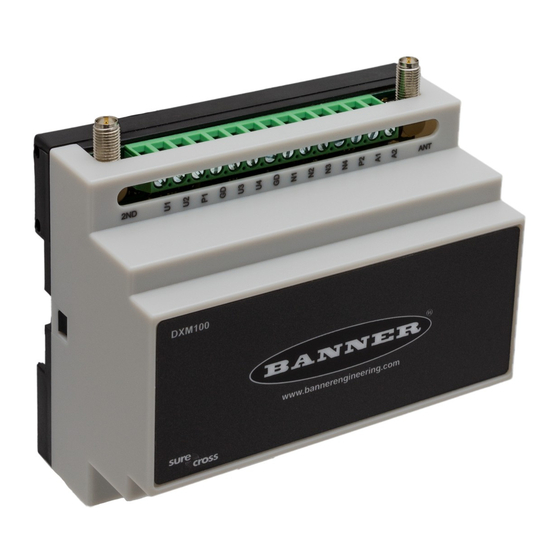
- Page 1 DXM100-Sx Wireless Modbus Slave Instruction Manual Original Instructions 188231 Rev. C 13 July 2018 © Banner Engineering Corp. All rights reserved 188231...
-
Page 2: Table Of Contents
DXM100-Sx Wireless Modbus Slave Contents 1 DXM100-Sx Overview ............................. 4 1.1 DXM100-Sx Modbus Slave System Overview ........................4 1.2 DXM Configuration Tool Overview ............................. 4 2 DXM Hardware Configuration Overview ........................5 3 ISM Radio ................................6 3.1 ISM Radio Board (Modbus Slave ID 1) ..........................6 3.1.1 DIP Switch Settings for the MultiHop HE5 Board Module .................. - Page 3 DXM100-Sx Wireless Modbus Slave 10.3 Contact Us ..................................44 10.4 Warnings ..................................45 10.5 Banner Engineering Corp. Limited Warranty .........................45...
-
Page 4: Dxm100-Sx Overview
DXM100-Sx Wireless Modbus Slave 1 DXM100-Sx Overview 1.1 DXM100-Sx Modbus Slave System Overview Banner's DXM Logic Controller integrates Banner's wireless radio and local I/O for a remote I/O device. Inputs/Outputs—On-board universal and programmable I/O ports connect to local sensors, indicators, and control equipment. -
Page 5: Dxm Hardware Configuration Overview
DXM100-Sx Wireless Modbus Slave 2 DXM Hardware Configuration Overview The DXM Slave can have multiple configurations. The DXM Slave will have a model number label on the housing. Use the model number and model table above to identify which boards are included in the controller. When opening the DXM Slave, follow proper ESD grounding procedures. -
Page 6: Ism Radio
DXM100-Sx Wireless Modbus Slave 3 ISM Radio 3.1 ISM Radio Board (Modbus Slave ID 1) The ISM embedded radio boards are available in either DX80 MultiHop or DX80 Performance. The DX80 MultiHop architecture creates a tree network with a Master radio and one or more Repeater/Slave devices. The MultiHop architecture is suited for networks requiring repeater devices to provide extended range or obstacle avoidance. -
Page 7: Dip Switch Settings For The Multihop He5 Board Module
DXM100-Sx Wireless Modbus Slave 3.1.1 DIP Switch Settings for the MultiHop HE5 Board Module D1 Switches D2 Switches Device Settings Serial line baud rate 19200 OR User defined receiver OFF* OFF* slots Serial line baud rate 38400 OR 32 receiver slots Serial line baud rate 9600 OR 128 receiver slots Serial line baud rate Custom OR 4 receiver slots Parity: None... -
Page 8: Binding The Ism Radio Of A Dxm100-Sx Modbus Slave
DXM100-Sx Wireless Modbus Slave For 2.4 GHz radios, the transmit power is fixed at 0.065 watt (18 dBm) and DIP switch 5 is used to set the frame timing. The default position (OFF) sets the frame timing to 60 milliseconds. To increase throughput, set the frame timing to 40 milliseconds. -
Page 9: O Base Board For The Dxm100-S1 Model
DXM100-Sx Wireless Modbus Slave 4 I/O Base Board for the DXM100-S1 Model 4.1 DXM100-S1 I/O Base Board Connections TVS1 A OUT 2 A OUT 1 R118 R122 R121 IC18 No connection Not used N3. NMOS OUT 3 PW. 12 to 30 V dc or solar power in (+) S-. -
Page 10: I/O Board Jumpers
DXM100-Sx Wireless Modbus Slave 4.1.2 I/O Board Jumpers Hardware jumpers on the DXM I/O board allow the user to select alternative pin operations. Turn the power off to the device before changing jumper positions. Jumper Function Positions Analog output characteristics for Defines current (0–20 mA) or voltage (0–10 V) for analog output 1 and 2. -
Page 11: Applying Power To The Dxm100-Sx Modbus Slave
DXM100-Sx Wireless Modbus Slave • For the DXM100-Sx Modbus Slave model, all switches on DIP switch K should be in the OFF position to use the Modbus register slave ID. 4.2 Applying Power to the DXM100-Sx Modbus Slave Apply power to the DXM100-Sx Modbus Slave using either 12 to 30 V dc or a 12 V dc solar panel and 12 V sealed lead acid battery. - Page 12 DXM100-Sx Wireless Modbus Slave Switched power 1 and 2 (pins 30 and 21) can be associated to any Universal input to apply power a sensor, take a reading, and then remove power from the sensor. This conserves power in battery-operated systems. The switched power supply can be used in one of two different ways: supplying courtesy power to an output pin or associated to an input.
- Page 13 DXM100-Sx Wireless Modbus Slave Input Parameter Universal Input Configuration Parameter Modbus Registers to Write To Universal Input 1 Universal Input 2 Universal Input 3 Universal Input 4 Extended Input Read 1007 1057 1107 1157 Input Out-of-Sync Enable 1008 1058 1108 1158 Extended Input Read The Extended Input Read is a bit field parameter that allows multiple inputs to be sampled with the same switch...
-
Page 14: Connecting A Battery To The Dxm Slave
DXM100-Sx Wireless Modbus Slave 4.2.3 Connecting a Battery to the DXM Slave When attaching a battery to the DXM Slave as a backup battery or as a solar battery, verify the charging algorithm is set properly. The factory default setting for the battery charging algorithm assumes you are using 12 to 30 V dc to recharge the battery. -
Page 15: Working With Solar Power
DXM100-Sx Wireless Modbus Slave On-board thermistor temperature This register stores the on-board thermistor reading in tenths of degrees C, this is not a calibrated input: divide by 10 to calculate the temperature in degrees C. For calibrated temperature inputs, define one of the universal inputs as a temperature input. -
Page 16: Recommended Solar Configurations
Solar Panel Banner solar panels come in two common sizes for the DXM Slave: 5 Watt and 20 Watt. Both panels are designed to work with the DXM Slave but provide different charging characteristics. Use the 5 watt panel for light duty operation and use the 20 watt panel when you require greater charging capabilities. -
Page 17: Monitoring Solar Operation
DXM100-Sx Wireless Modbus Slave Solar panel and battery combinations for a DXM Slave system Battery Capacity 4 Solar Panel Days of Autonomy DXM mA DXM Controller 20 watt 20 Ahr 10 days 35 mA DXM Controller with ISM radio and Cellular Modem 4.3.4 Monitoring Solar Operation The DXM solar controller provides Modbus registers that allow the user to monitor the state of the solar panel input voltage, the battery voltage, the charging current, and the temperature in °C. -
Page 18: Inputs And Outputs
Thermistor Input A thermistor input must use a 10k temperature thermistor between ground and the universal input. The thermistor must be a 10k NTC (Banner model number BWA-THERMISTOR-002) or equivalent. Select the temperature Modbus I/O Registers for the conversion of degrees C (default) or degrees F by writing Modbus registers defined in DXM100-S1x I/O Base Board on page 21. -
Page 19: Nmos Outputs
DXM100-Sx Wireless Modbus Slave Potentiometer Input A potentiometer input is created from three inputs: a voltage source (pin 30) that supplies 5 V to the potentiometer and two inputs set to voltage inputs to read the voltage across the potentiometer. See the DXM tech note for setting up a potentiometer. - Page 20 DXM100-Sx Wireless Modbus Slave 2. Remove the DXM cover. 3. Change the hardware jumper position (see the table for the pin number and DXM100-B1 I/O Base Board Connections for the pin locations). 4. Replace the DXM cover. 5. Restore power to the DXM. 6.
-
Page 21: Modbus I/O Registers For The Dxm100-S1X I/O Base Board
DXM100-Sx Wireless Modbus Slave Minimum Analog Value. The Minimum Analog Value register stores the minimum allowed analog value. The specific units of measure apply to register value. For example, the register may contain 4000, for 4 mA, or for a voltage output the register may contain 2000, for 2 volts. - Page 22 DXM100-Sx Wireless Modbus Slave Universal Input Parameters Registers Universal Inputs Temperature °C/°F Registers 3304 3324 3344 3364 Input Type Registers 3306 3326 3346 3366 Threshold Registers 3308 3328 3348 3368 Hysteresis Registers 3309 3329 3349 3369 Enable Rising Registers 4908 4928 4948 4968...
-
Page 23: O Base Board For The Dxm100-S2 Model
DXM100-Sx Wireless Modbus Slave 5 I/O Base Board for the DXM100-S2 Model 5.1 DXM100-B2 and S2 I/O Base Board Connections TVS1 No connection 2B. DLatch 2B N3. NMOS OUT 3 PW. 12–30 V dc or solar power in (+) S-. Secondary RS-485 – N2. -
Page 24: Setting The Modbus Slave Id On The I/O Base Board
DXM100-Sx Wireless Modbus Slave 5.1.2 Setting the Modbus Slave ID on the I/O Base Board Only DXM100-S1 and -S1R2 Slave models require that the Modbus Slave ID to be adjusted on the I/O base board. The DXM100-Sx Modbus Slave models use DIP switches J and K to set the Modbus Slave ID. This device can use a Modbus register 6804 in the I/O board to access the full range of Modbus Slave IDs. -
Page 25: Using Courtesy Power Or Switch Power
DXM100-Sx Wireless Modbus Slave Description Pin 4 Solar or backup battery positive input. Battery voltage must be less than 15 V dc. Use only a sealed lead acid (SLA) battery. 5.2.1 Using Courtesy Power or Switch Power Pin 18 of the DXM100-Sx Modbus Slave is a constant power source that supplies 5 volts up to 500 mA. Pins 21 (switch power 2) and 30 (switch power 1) are switched power outputs. - Page 26 DXM100-Sx Wireless Modbus Slave Courtesy Power Output Configuration Parameters 7 Modbus Registers to Write To Switched Power 1 Switched Power 2 Switched Power Enable 2201 2251 Voltage 3601 3621 Default Output 3602 3622 Output Register Default Output Set the register value to 1 for continuous power. The default setting is 0. Cycle power if this register value is changed.
-
Page 27: Connecting A Battery To The Dxm Slave
DXM100-Sx Wireless Modbus Slave Extended Input Read The Extended Input Read is a bit field parameter that allows multiple inputs to be sampled with the same switch power parameters. If the bit field is set to 0x000F, the first four inputs are sampled after the switch power parameters are satisfied. If the Extended Input Read parameter is set in the Universal input 1 configuration registers, set Universal inputs 2 through 4 Extended Input Read and Sample Interval parameters to zero. -
Page 28: Supplying Power From A Solar Panel
DXM100-Sx Wireless Modbus Slave • When using a solar panel, connect the solar panel output to pin 2 and connect the ground to pin 3. Connect the 12 Supplying Power from a Solar V dc SLA battery to pin 4 (+) and pin 5 (-). To change the charging algorithm, refer to Panel on page 14. -
Page 29: Working With Solar Power
Solar Panel Banner solar panels come in two common sizes for the DXM Slave: 5 Watt and 20 Watt. Both panels are designed to work with the DXM Slave but provide different charging characteristics. Use the 5 watt panel for light duty operation and use the 20 watt panel when you require greater charging capabilities. -
Page 30: Recommended Solar Configurations
DXM100-Sx Wireless Modbus Slave Solar Panel Voltage Current Typical DXM Configurations 5 Watt 17 V 0.29 A DXM slave controller, ISM radio, I/O base board 20 Watt 21 V DXM Controller with ISM radio and Cellular modem Photovoltaic panels are very sensitive to shading. Unlike solar thermal panels, PV solar panels cannot tolerate shading from a branch of a leafless tree or small amounts of snow in the corners of the panel. -
Page 31: Connecting The Communication Pins
DXM100-Sx Wireless Modbus Slave Figure 4. Battery Voltage (mV) - Cloudy First Day 5.4 Connecting the Communication Pins The base board communications connection for external Modbus device uses the primary RS-485. RS-485. The primary RS-485 bus is a common bus shared with the ISM radio board (Modbus Slave ID 1). RS-232. - Page 32 Thermistor Input A thermistor input must use a 10k temperature thermistor between ground and the universal input. The thermistor must be a 10k NTC (Banner model number BWA-THERMISTOR-002) or equivalent. Select the temperature Modbus I/O Registers for the conversion of degrees C (default) or degrees F by writing Modbus registers defined in DXM100-S1x I/O Base Board on page 21.
-
Page 33: Nmos Outputs
DXM100-Sx Wireless Modbus Slave 3. Write a 3 to Modbus register 4008 on Modbus Slave ID 11 (I/O board). 4. Cycle power to the device. 5. Using the Register View tab, read register 4008 to verify it is set to 3. 5.5.2 NMOS Outputs NMOS Discrete Modbus Register... -
Page 34: Dc Latching Outputs
DXM100-Sx Wireless Modbus Slave Enable Register Full Scale. Set to 1 to enable a linear range from 0 to 65535 for specified input range. For a 4 to 20 mA output, a value of 0 represents 4 mA and 65535 represents 20 mA. Set this parameter to 0 to store readings in unit-specific data. - Page 35 DXM100-Sx Wireless Modbus Slave Device Command The SDI-12 interface supports "M!" or "C!" commands. Use the Device Command parameter to define which command to use for this device. The factory default is "M!" commands for all devices (value of 10 in the Modbus register).
- Page 36 In most cases, parameters will not need to be adjusted but if needed there are three common SDI-12 device parameters that control the communications and power of the SDI-12 device. Contact Banner Engineering Corp support for more guidance.
-
Page 37: Modbus I/O Registers For The Dxm100-S2X I/O Base Board
DXM100-Sx Wireless Modbus Slave Models Technical Note Adcon Telemetry HydraProbeII SDI-12 and the AquaCheck Sub-Surface Soil Moisture Probe AquaCheck Sub-surface Probe SDI-12 and the Decagon 5TE Soil Moisture Probe Decagon MPS-2, MPS-6, 5TE, TS1, T8 SDI-12 and the Decagon GS3 Soil Moisture Probe SDI-12 and the Decagon MPS-2 Soil Moisture Probe HSTI HydraScout... - Page 38 DXM100-Sx Wireless Modbus Slave Modbus Configuration Registers for the I/O Each input or output on the I/O base board has associated Modbus registers that configure its operation. Universal Input Parameters Registers Universal Inputs Enable Full Scale Registers 3303 3323 3343 3363 Temperature °C/°F Registers 3304...
-
Page 39: Dxm Modbus Registers
DXM100-Sx Wireless Modbus Slave 6 DXM Modbus Registers All Modbus registers are defined as 16-bit Modbus Holding Registers. When connecting external Modbus slave devices, only use Modbus slave IDs 2 through 198. DXM Internal Modbus Slave IDs (factory default) Modbus Slave ID Device ISM Radio—MultiHop wireless devices connected to the internal MultiHop radio should be assigned Modbus Slave addresses starting at 11. -
Page 40: Restoring Factory Default Settings
DXM100-Sx Wireless Modbus Slave 7 Restoring Factory Default Settings To reset to factory defaults, write to two Modbus registers in the I/O board. The default slave ID for the I/O board is 11. To reset the DXM I/O board parameters: 1. -
Page 41: Dxm100 Dimensions
DXM100-Sx Wireless Modbus Slave 8 DXM100 Dimensions 59.5 mm [2.34”] 20.4 mm 35 mm 104 mm [0.8”] [1.38”] [4.09”] 86 mm [3.39”] 94.6 mm [3.72”] All measurements are listed in millimeters, unless noted otherwise. www.bannerengineering.com - Tel: +1.763.544.3164... -
Page 42: Accessories
DXM100-Sx Wireless Modbus Slave 9 Accessories Accessories List For a complete list of all the accessories for the Sure Cross wireless product line, please download the (p/n b_3147091) Cordsets Misc Accessories MQDC1-506—5-pin M12/Euro-style, straight, single ended, 6 ft BWA-CG.5-3X5.6-10—Cable Gland Pack: 1/2-inch NPT, Cordgrip for 3 holes of 2.8 to 5.6 mm diam, qty 10 MQDC1-530—5-pin M12/Euro-style, straight, single ended, 30 ft BWA-HW-052—... -
Page 43: Additional Information
Ethernet network connection. In a continuing effort to provide the best operation for the DXM Slave, stay connected with Banner Engineering Corp to hear about the latest updates through the Banner website. Create a login today to stay informed of all Banner product releases. -
Page 44: Dxm Security
TheDXM Slave does not run a Linux or Windows based operating system but an embedded RTOS environment. As a proprietary operating system, the security aspects are easier to manage and minimize. Security updates are released through the Banner website and New Product Release Announcements (NPRA). 10.3 Contact Us... - Page 45 10.5 Banner Engineering Corp. Limited Warranty Banner Engineering Corp. warrants its products to be free from defects in material and workmanship for one year following the date of shipment. Banner Engineering Corp. will repair or replace, free of charge, any product of its manufacture which, at the time it is returned to the factory, is found to have been defective during the warranty period. This warranty does not cover damage or liability for misuse, abuse, or the improper application or installation of the Banner product.
Need help?
Do you have a question about the DXM100-S Series and is the answer not in the manual?
Questions and answers