
Related Manuals for Banner DXM150-S2


Summary of Contents for Banner DXM150-S2
- Page 1 DXM150-Sx Wireless Modbus Slave Instruction Manual Original Instructions 195455 Rev. B 13 July 2018 © Banner Engineering Corp. All rights reserved 195455...
-
Page 2: Table Of Contents
4.6.2 Setting the DXM I/O Board Modbus Slave ID using Modbus Registers .............. 21 4.6.3 I/O Board Jumpers .............................. 21 5 I/O Base Board for the DXM150-S2 Models ......................23 5.1 Board Connections ................................. 23 5.1.1 DIP Switches for the I/O Board .......................... - Page 3 DXM150-Sx Wireless Modbus Slave 9.2.2 Website Information ............................40 9.2.3 Feature Requests ..............................40 9.2.4 Potential DXM Issues ............................40 9.2.5 DXM Security ...............................41 9.3 Contact Us ..................................41 10 Warnings ................................43 10.1 Banner Engineering Corp. Limited Warranty .........................43...
-
Page 4: Dxm150-Sx Overview
DXM150-Sx Wireless Modbus Slave 1 DXM150-Sx Overview 1.1 DXM150-Sx Wireless Modbus Slave System Overview Banner's DXM Logic Controller integrates Banner's wireless radio and local I/O for a remote I/O device. Inputs/Outputs—On-board universal and programmable I/O ports connect to local sensors, indicators, and control equipment. -
Page 5: Dxm150-Sx Hardware Overview
DXM150-Sx Wireless Modbus Slave 2 DXM150-Sx Hardware Overview 2.1 DXM Hardware Configuration Overview The DXM Modbus Slave can have multiple configurations. The DXM Modbus Slave will have a model number label on the housing. Use the model number and model table above to identify which boards are included in the controller. When opening the DXM Modbus Slave, follow proper ESD grounding procedures. -
Page 6: Ism Radio
DXM150-Sx Wireless Modbus Slave 3 ISM Radio 3.1 ISM Radio Board (Modbus Slave ID 1) The ISM embedded radio boards are available in either DX80 MultiHop or DX80 Performance. The DX80 MultiHop architecture creates a tree network with a Master radio and one or more Repeater/Slave devices. The MultiHop architecture is suited for networks requiring repeater devices to provide extended range or obstacle avoidance. -
Page 7: Dip Switch Settings For The Multihop He5 Board Module
DXM150-Sx Wireless Modbus Slave 3.1.1 DIP Switch Settings for the MultiHop HE5 Board Module D1 Switches D2 Switches Device Settings Serial line baud rate 19200 OR User defined receiver OFF* OFF* slots Serial line baud rate 38400 OR 32 receiver slots Serial line baud rate 9600 OR 128 receiver slots Serial line baud rate Custom OR 4 receiver slots Parity: None... -
Page 8: Binding The Ism Radio Of A Dxm150-Sx Wireless Modbus Slave
DXM150-Sx Wireless Modbus Slave For 2.4 GHz radios, the transmit power is fixed at 0.065 watt (18 dBm) and DIP switch 5 is used to set the frame timing. The default position (OFF) sets the frame timing to 60 milliseconds. To increase throughput, set the frame timing to 40 milliseconds. -
Page 9: O Base Board For The Dxm150-S1 Model
DXM150-Sx Wireless Modbus Slave 4 I/O Base Board for the DXM150-S1 Model 4.1 Board Connections Figure 1. Board Connections Input 2B Analog Output 1 (0 to 10 V) 12 to 30 V dc or solar power in (+) Ground Ground Ground Output 1 Normally Open PWR Out - Jumper... -
Page 10: Dip Switches For The I/O Board
DXM150-Sx Wireless Modbus Slave 4.1.1 DIP Switches for the I/O Board The DXM150-Sx Wireless Modbus Slave I/O board DIP switches are set from the factory to Modbus Slave ID 11. For more Setting the Modbus Slave ID on the I/O Base Board . information, refer to 4.1.2 I/O Board Jumpers Hardware jumpers on the DXM I/O board allow the user to select alternative pin operations. -
Page 11: Connecting A Battery To The Dxm Modbus Slave
DXM150-Sx Wireless Modbus Slave To change the charging algorithm from the menu system: 1. From the DXM Modbus Slave LCD menu, navigate to System Config > I/O Board > Charger. 2. Select Solar for solar panel configurations. To change the charging algorithm by writing to Modbus register 6071 on the I/O base board (Slave ID 11): 1. -
Page 12: Working With Solar Power
DXM150-Sx Wireless Modbus Slave Modbus Slave ID Modbus Register Description 11 * 6071 Battery backup charging algorithm. 0 = Battery is recharged from a solar panel 1 = Battery is recharged from 12 to 30 V dc (default) * The Modbus Slave ID for the base board is set at the factory and may be changed using the base board DIP switch settings. -
Page 13: Recommended Solar Configurations
Solar Panel Banner solar panels come in two common sizes for the DXM Modbus Slave: 5 Watt and 20 Watt. Both panels are designed to work with the DXM Modbus Slave but provide different charging characteristics. Use the 5 watt panel for light duty operation and use the 20 watt panel when you require greater charging capabilities. -
Page 14: Monitoring Solar Operation
DXM150-Sx Wireless Modbus Slave Solar panel and battery combinations for a DXM Modbus Slave system Battery Capacity 1 Solar Panel Days of Autonomy DXM mA DXM Controller 20 watt 20 Ahr 10 days 35 mA DXM Controller with ISM radio and Cellular Modem 4.3.4 Monitoring Solar Operation The DXM solar controller provides Modbus registers that allow the user to monitor the state of the solar panel input voltage, the battery voltage, the charging current, and the temperature in °C. -
Page 15: Inputs And Outputs
DXM150-Sx Wireless Modbus Slave Parameter Description Pin 9 RS-232 Tx Serial RS-232 connection. This bus must use a ground connection between devices to operate correctly. Pin 10 RS-232 Rx Pin 13 Secondary RS-485 – Not used Pin 14 Secondary RS-485 + Pin 15 CANL –... -
Page 16: Relay Outputs
DXM150-Sx Wireless Modbus Slave 4.5.2 Relay Outputs Output Description Wiring Pin 19 Output 1: Normally Open Pin 20 Output 1: Common Normally open Pin 21 Output 1: Normally Closed SPDT (Form C) relay, 250 V ac, 16 A Common Pin 22 Output 3: Normally Open Pin 23 Output 3: Common... -
Page 17: Universal Inputs
8 = NPN Raw Fast (default) Thermistor Input. A thermistor input must use a 10k thermistor between ground and the universal input. The thermistor must be a 10k NTC (Banner model number BWA-THERMISTOR-002) or equivalent. Select the temperature conversion of degrees I/O Base Board . - Page 18 DXM150-Sx Wireless Modbus Slave Bridge Input. The bridge input is not implemented yet. NPN vs NPN Raw Fast. The difference between NPN and NPN Raw Fast is the amount of settling time given to the input. Switch the input type to NPN if the input is not detecting a transition. Example: Configure Input 1 as a Synchronous Counter 1.
-
Page 19: Modbus Registers
DXM150-Sx Wireless Modbus Slave 4. To set universal input 8 as the sense, write Modbus register 3446 with 5 (Potentiometer Sense). 5. Verify the jumpers are still set to their default position. One jumper should be on pins 1 and 3 to get a 2.7 V source voltage out pin 45. - Page 20 DXM150-Sx Wireless Modbus Slave Universal Input Parameter Modbus Registers Universal Inputs Enable Falling 4909 4929 4949 4969 4989 5009 5029 5049 High Register for Counter 4910 4930 4950 4970 4990 5010 5030 5050 Low Register for Counter 4911 4931 4951 4971 4991 5011...
-
Page 21: Setting The Modbus Slave Id On The I/O Base Board
DXM150-Sx Wireless Modbus Slave * Setting Enable Full Scale to 1 sets the ranges to a linear scale of 0 to 65535. 4.6 Setting the Modbus Slave ID on the I/O Base Board Only DXM150-Sx and SxR2 Modbus Slave models require that the Modbus Slave ID to be adjusted on the I/O base board. The DXM150-Sx Wireless Modbus Slave devices use DIP switch J and rotary dial K to set the Modbus slave ID. - Page 22 DXM150-Sx Wireless Modbus Slave Jumper Function Positions Courtesy power output Jumper 2 is the power jumper for pin 45. Jumper 1 is the power jumper for pin 35. • The pin 45 jumper selects 2.7 V when in the "a" position and 12 V battery in the "b"...
-
Page 23: O Base Board For The Dxm150-S2 Models
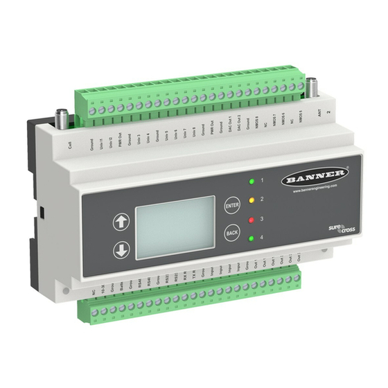
5 I/O Base Board for the DXM150-S2 Models 5.1 Board Connections Figure 5. Board Connections ********* THIS IS THE TABLE FOR THE DXM150-B2. PLEASE MARK THIS UP FOR THE DXM150-S2. ********* Input 2B Analog Output 1 (0–20 mA or 0–10 V) -
Page 24: Dip Switches For The I/O Board
DXM150-Sx Wireless Modbus Slave Cellular Antenna Radio Binding Button ISM Radio Connection Radio LED RS-485 Jumpers Modbus Slave ID DIP Switches Radio Module Antenna RS-232 Jumpers Rotary Dials SAM4 Processor Board Connection 5.1.1 DIP Switches for the I/O Board The DXM150-Sx Wireless Modbus Slave I/O board DIP switches are set from the factory to Modbus Slave ID 11. For more information, refer to Setting the Modbus Slave ID on the I/O Base Board . -
Page 25: Supplying Power From A Solar Panel
DXM150-Sx Wireless Modbus Slave Description Pin 35, Pin 45 These outputs are controlled by hardware jumpers. Jumper 2 is the power jumper for pin 45. Jumper 1 is the power jumper for pin 35. Refer to the wiring board for more information. -
Page 26: Connecting A Battery To The Dxm Modbus Slave
DXM150-Sx Wireless Modbus Slave 5.2.2 Connecting a Battery to the DXM Modbus Slave When attaching a battery to the DXM Modbus Slave as a backup battery or as a solar battery, verify the charging algorithm is set properly. The factory default setting for the battery charging algorithm assumes you are using 12 to 30 V dc to recharge the battery. -
Page 27: Recommended Solar Configurations
Solar Panel Banner solar panels come in two common sizes for the DXM Modbus Slave: 5 Watt and 20 Watt. Both panels are designed to work with the DXM Modbus Slave but provide different charging characteristics. Use the 5 watt panel for light duty operation and use the 20 watt panel when you require greater charging capabilities. -
Page 28: Monitoring Solar Operation
DXM150-Sx Wireless Modbus Slave Solar panel and battery combinations for a DXM Modbus Slave system Battery Capacity 4 Solar Panel Days of Autonomy DXM mA DXM Controller 5 watt 10 Ahr 10 days 25 mA DXM Slave Controller - ISM radio and I/O base board 20 watt 14 Ahr 10 days... -
Page 29: Inputs And Outputs
Thermistor Input. A thermistor input must use a 10k thermistor between ground and the universal input. The thermistor must be a 10k NTC (Banner model number BWA-THERMISTOR-002) or equivalent. Select the temperature conversion of degrees C (default) or degrees F by writing to the Modbus registers defined in I/O Base Board . - Page 30 DXM150-Sx Wireless Modbus Slave Example: Configure Input 1 as a Synchronous Counter 1. Connect the DXM Modbus Slave to the PC. 2. Launch the DXM Configuration Tool software. 3. Connect to the DXM Modbus Slave by selecting the Device > Connection Settings menu option. You may connect using either USB or Ethernet.
-
Page 31: Pnp And Npn Outputs
DXM150-Sx Wireless Modbus Slave 6. Connect one potentiometer side to power output (pin 45), connect the tap point of the pot to universal input 8 (pin 37), and connect the other end of the pot to ground (pin 36). 5.5.2 PNP and NPN Outputs Output Modbus Description... -
Page 32: Isolated Discrete Inputs
DXM150-Sx Wireless Modbus Slave Default Output State. The Default Output State parameter represents the default condition of the analog output. When an error condition exists, the outputs are set to this 16-bit user-defined output state. To define the error conditions for device outputs, refer to the MultiHop default output parameters 2950-2954. - Page 33 DXM150-Sx Wireless Modbus Slave Modbus Registers for the I/O Board The I/O board is Slave ID 11. Base Board Input Connection Base Board Output Connection Modbus Register Description Modbus Register Description Optically isolated input 1 PNP/NPN Output 1 Optically isolated input 2 PNP/NPN Output 2 Universal input 1 PNP/NPN Output 3...
- Page 34 DXM150-Sx Wireless Modbus Slave Enable Rising/Falling. Use these registers to enable the universal input logic to count on a rising transition or a falling transition. Write a one (1) to enable; write a zero (0) to disable. High/Low Register for Counter. The low and high registers for the counter hold the 32-bit counter value. To erase the counter, write zeroes to both registers.
-
Page 35: Setting The Modbus Slave Id On The I/O Base Board
DXM150-Sx Wireless Modbus Slave 5.6 Setting the Modbus Slave ID on the I/O Base Board Only DXM150-Sx and SxR2 Modbus Slave models require that the Modbus Slave ID to be adjusted on the I/O base board. The DXM150-Sx Wireless Modbus Slave devices use DIP switch J and rotary dial K to set the Modbus slave ID. The device can use a Modbus register 6804 in the I/O board to access the full range of Modbus Slave IDs. - Page 36 DXM150-Sx Wireless Modbus Slave 2. Write a 10 to Modbus register 4151 To reset only the I/O board: 1. Write a 0 to Modbus register 4152 2. Write a 10 to Modbus register 4151 Modbus Register Values Description 4151 0–255 Reset/restore trigger.
-
Page 37: Restoring Factory Default Settings
DXM150-Sx Wireless Modbus Slave 6 Restoring Factory Default Settings To reset to factory defaults, write to two Modbus registers in the I/O board. The default slave ID for the I/O board is 11. To reset the DXM I/O board parameters: 1. -
Page 38: Dxm150 Dimensions
DXM150-Sx Wireless Modbus Slave 7 DXM150 Dimensions 59.5 mm [2.34”] 35 mm 156 mm [1.38”] [6.14”] 85 mm [3.35”] 94.6 mm [3.72”] All measurements are listed in millimeters [inches], unless noted otherwise. www.bannerengineering.com - Tel: +1.763.544.3164... -
Page 39: Accessories
DXM150-Sx Wireless Modbus Slave 8 Accessories Accessories List For a complete list of all the accessories for the Sure Cross wireless product line, please download the (p/n b_3147091) Cordsets Misc Accessories MQDC1-506—5-pin M12/Euro-style, straight, single ended, 6 ft BWA-CG.5-3X5.6-10—Cable Gland Pack: 1/2-inch NPT, Cordgrip for 3 holes of 2.8 to 5.6 mm diam, qty 10 MQDC1-530—5-pin M12/Euro-style, straight, single ended, 30 ft BWA-HW-052—... -
Page 40: Additional Information
Firmware updates and description details are found on the Banner website. Customers with critical update requirements will get access to pre-released firmware from the factory. 9.2.2 Website Information The Banner website is the main method of disseminating DXM Modbus Slave information to customers. The data found on the website include: •... -
Page 41: Dxm Security
TheDXM Modbus Slave does not run a Linux or Windows based operating system but an embedded RTOS environment. As a proprietary operating system, the security aspects are easier to manage and minimize. Security updates are released through the Banner website and New Product Release Announcements (NPRA). 9.3 Contact Us... - Page 42 DXM150-Sx Wireless Modbus Slave Japan Address: Phone: +81 (0)6 6309 0411 Banner Engineering Japan Website: www.bannerengineering.com Cent-Urban Building 305 3-23-15 Nishi-Nakajima Yodogawa-Ku Email: mail@bannerengineering.co.jp Osaka 532-0011, Japan Taiwan Address: Phone: +886 (0)2 8751 9966 www.bannerengineering.com Banner Engineering Taiwan Website: 8F-2, No. 308 Section 1, Neihu Road Email: info@bannerengineering.com.tw...
-
Page 43: Warnings
10.1 Banner Engineering Corp. Limited Warranty Banner Engineering Corp. warrants its products to be free from defects in material and workmanship for one year following the date of shipment. Banner Engineering Corp. will repair or replace, free of charge, any product of its manufacture which, at the time it is returned to the factory, is found to have been defective during the warranty period. This warranty does not cover damage or liability for misuse, abuse, or the improper application or installation of the Banner product.
Need help?
Do you have a question about the DXM150-S2 and is the answer not in the manual?
Questions and answers