
Related Manuals for Nidec LEROY-SOMER POWERDRIVE MD2R Series


Summary of Contents for Nidec LEROY-SOMER POWERDRIVE MD2R Series
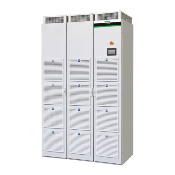
- Page 1 Installation guide POWERDRIVE MD2R 60T to 1700T 270TH to 1500TH Low Harmonics Active Front End high-power free-standing drive solution Reference : 4948 - 2017.11 / d...
- Page 2 NOTE LEROY-SOMER reserves the right to modify the characteristics of its products at any time in order to incorporate the latest technological developments. The information contained in this document may therefore be changed without notice. CAUTION For the user's own safety, this variable speed drive must be connected to an approved earth terminal).
- Page 3 SAFETY AND OPERATING INSTRUCTIONS FOR VARIABLE SPEED DRIVES (In accordance with the low voltage directive 2014/35/EU) Throughout the manual, this symbol warns of consequences which may arise from inappropriate use of the drive, since electrical risks may lead to material or physical damage as well as constituting a fire hazard. 1 - General Depending on their degree of protection, the variable speed 5 - Electrical connection...
- Page 4 FOREWORD This manual describes the installation of POWERDRIVE MD2R variable speed drives. It also gives details of all its options and extensions which the user may choose to suit his requirements. POWERDRIVE MD2R Parameter setting Standard • HMI • High-speed fuses •...
-
Page 5: Table Of Contents
CONTENTS 1 - GENERAL INFORMATION ..........................7 1.1 - General ................................ 7 1.2 - Product designation ............................ 7 1.3 - Environmental characteristics ........................7 1.4 - Electrical characteristics ..........................8 1.4.1 - General characteristics............................8 1.4.2 - Electrical characteristics ............................8 1.4.3 - Derating at low frequency ............................ - Page 6 5 - PARAMETER-SETTING INTERFACE AND OPTIONS ..................32 5.1 - Parameter setting interfaces ........................32 5.1.1 - Location of the drive connectors / ports ....................... 32 5.1.2 - MDX-Powerscreen .............................. 32 5.2 - Add-on options ............................34 5.2.1 - Fieldbus modules ..............................34 5.2.2 - Speed feedback options ............................
-
Page 7: General Information
GENERAL INFORMATION 1 - GENERAL INFORMATION 1.3 - Environmental characteristics 1.1 - General Characteristic Level The POWERDRIVE MD2R is a variable speed drive with Protection IP21 (IP54 as an option) active rectifier allowing to feed back the braking energy of Storage and transport -30°C to +60°C (see section 7.2) electrical machine to the mains (operation in the 4 quadrant... -
Page 8: Electrical Characteristics
GENERAL INFORMATION 1.4 - Electrical characteristics All work relating to installation, commissioning and maintenance must be carried out by experienced, qualified personnel. 1.4.1 - General characteristics Characteristic Level 3-phase mains supply: 400 V -10% to 480 V +5% ("T" ratings) or Power supply voltage 525 V -10% to 690 V +5% ("TH"... -
Page 9: Derating At Low Frequency
GENERAL INFORMATION POWERDRIVE MD2R xxxTH Inverter switching frequency = 3 kHz - Active rectifier in factory settings Ambient temperature ≤ 40°C (35°C avec option IP54) - altitude ≤ 1000 m. Heavy duty Normal duty POWERDRIVE Maximum Imax (60s) Pout at Pout at Pout at Pout at... -
Page 10: Derating According To The Temperature And Switching Frequency Form Motor Inverter
GENERAL INFORMATION 1.4.4 - Derating according to the temperature and switching frequency form motor inverter Ambient temperature ≤ 40°C (≤ 35°C with IP54 option) - altitude ≤ 1000 m Ico (A) Rating Heavy duty Normal duty 2 kHz 3 kHz 4 kHz 5 kHz 6 kHz... - Page 11 GENERAL INFORMATION Ambient temperature ≤ 50°C (≤ 45°C with IP54 option) - altitude ≤ 1000 m. Ico (A) Rating Heavy duty Normal duty 2 kHz 3 kHz 4 kHz 5 kHz 6 kHz 2 kHz 3 kHz 4 kHz 5 kHz 6 kHz 400V / 460V mains supply 100T...
-
Page 12: Powerdrive Md2R Synoptics
GENERAL INFORMATION 1.5 - POWERDRIVE MD2R synoptics POWERDRIVE MD2R are composed of : • AFE rectifier • Inverter connected to the motor • Sinus filter • DC bus preloading device • PCB with 32 bit Microcontroller • POWERDRIVE MD2R 180T to 270T •... - Page 13 GENERAL INFORMATION • POWERDRIVE MD2R 340T to 900T and POWERDRIVE MD2R 270TH to 900TH OPTIONNAL SWITCH 600T / 900T 600TH / 900TH SINUS SINUS FILTER FILTER (FPB) (FO) aR FUSES aR FUSES INPUT INPUT FUSES FUSES BOARD BOARD REGEN REGEN INDUCTOR INDUCTOR 230V...
-
Page 14: Mechanical Installation
MECHANICAL INSTALLATION 2 - MECHANICAL INSTALLATION • It is the responsibility of the owner or user of the POWERDRIVE MD2R to ensure that the installation, L = 600 mm operation and maintenance of the drive and its options or 600 + 400 mm comply with legislation relating to the safety of personnel and equipment and with the current regulations of the 60°... -
Page 15: Installation Recommendations
MECHANICAL INSTALLATION 2.3 - Installation recommendations 2.5 - Assembly and dismantling of the IP54 roof The drives must be installed away from conducting dust, corrosive gas, dripping water and any source of • Assembly: condensation. Prevent access by unauthorised personnel. 1 - Dismantle the 4 lifting rings or the 2 lifting rails. -
Page 16: Dimensions
MECHANICAL INSTALLATION 2.6 - Dimensions The cabinet-mounted POWERDRIVE MD2R solution is obtained by assembling cabinet modules 600 mm wide and 600 mm deep. The table below gives the product width (W in mm) depending on the options incorporated: W/o options (-B) With options (-O) Width Width... -
Page 17: Weight
MECHANICAL INSTALLATION 2.7 - Weight 2.9 - Drive ventilation flow rates and noise levels The values indicated in the table below are maximum net weights. Forced Noise level Rating Maximum weight (kg) ventilation Rating with IP21 flow rates 60T and 75T (dBA) /hr) 100T to 150T... -
Page 18: Connections
CONNECTIONS 3 - CONNECTIONS 3.1.2 - Electronics and forced ventilation power supply The control electronics and forced ventilation units are • All connection work must be performed by qualified electricians in accordance with the laws in supplied through a single-phase transformer which primary force in the country in which the drive is installed. -
Page 19: Location Of Power Terminal Blocks And Fuse Boards
CONNECTIONS 3.1.4 - Location of power terminal blocks and fuse boards Inverter control board (motor) with control terminal block Synchronous rectifier control board Fuse board and external power supply (included in the chassis oh the product from 60T to 270T) Rating 180T to 270T Rating 60T to 150T P1 P2... - Page 20 CONNECTIONS Rating 340T to 570T and 270TH to 500TH P1 P2 P1 P2 4 x d =11 50 75 Front side of the power terminal block right side POWERDRIVE MD2R Installation guide 4948 - 2017.11 / d...
- Page 21 CONNECTIONS Rating 600T to 1100T and 600TH to 900TH P1 P2 P1 P2 P1 P2 P1 P2 50 75 Front side of the power terminal block 4 x d =11 Right side POWERDRIVE MD2R Installation guide 4948 - 2017.11 / d...
-
Page 22: Cables And Fuses
CONNECTIONS 3.1.4 - Cables and fuses • It is the responsibility of the user to connect and provide protection for the POWERDRIVE MD2R in accordance with the current legislation and regulations in the country of use. This is particularly important with regard to the size of the cables, the type and rating of fuses, the earth or ground connection, powering down, acknowledging trips, isolation and protection against overcurrents. - Page 23 CONNECTIONS Main power supply 575V/60Hz - 690V/50Hz Motor Cable Cable Rating Fuses cross-section Ico(A) cross-section Gg (1) (mm²) (3) (mm²) (4) 270TH 3x150 + PE 3x150 + PE 340TH 3x185 + PE 3x185 + PE 400TH 2x[3x120 + PE] 2x[3x120 + PE] 500TH 2x[3x150 + PE] 2x[3x150 + PE]...
-
Page 24: Connection Of The Control
CONNECTIONS 3.2 - Connection of the control AI1+ Differential analog input 1 (+) AI1- Differential analog input 1 (-) • The POWERDRIVE MD2R inputs have a positive logic configuration. Using a drive with a control system Factory setting 0-10V speed reference which has a different control logic may cause unexpedted ±... - Page 25 CONNECTIONS Analog output Digital output Factory setting 4-20 mA motor current signal Factory setting Zero speed Bipolar analog voltage in common Characteristic Open collector Output type mode or unipolar current in Absolute maximum voltage + 30 V/0 V common mode Overload current 150 mA Resolution...
-
Page 26: Factory Configuration Of Control Terminal Blocks
CONNECTIONS 3.2.3 - Factory configuration of control Nota : For more details on the parameters, please refer to the commissioning manual ref.4617 Specific setting of the terminal blocks active rectifier's control block: POWERDRIVE MD2R include two modules control : • An AFE rectifier module. -
Page 27: Sto-1/Sto-2 Inputs: Safe Torque Off Function
CONNECTIONS 3.3 - STO-1/STO-2 inputs: Safe Torque 3.3.1 - Single channel locking (SIL1 - PLb) Off function 3-phase AC power supply, in accordance with safety standard IEC/EN 62061: 2005 and EN/ISO 13849-1: 2006 - Single The STO-1 and STO-2 inputs are safety inputs that can be channel locking (SIL1 - PLb). -
Page 28: General Emc - Harmonics - Mains Interference
GENERAL EMC - HARMONICS - MAINS INTERFERENCE 4 - GENERAL EMC - HARMONICS - 4.3 - Radio-frequency interference: Emission MAINS INTERFERENCE 4.3.1 - General The power structure of frequency inverters leads to the occurrence of two types of phenomenom : In order to limit motor losses and obtain a low level of - Low-frequency harmonics fed back to the mains supply motor noise, frequency inverters use high-speed switches... -
Page 29: Mains Supply
GENERAL EMC - HARMONICS - MAINS INTERFERENCE 4.4 - Mains supply 4.4.3 - Unbalanced power supply 4.4.1 - General Similar to what is observed on an electric motor, the line current imbalance of a drive operating on an unbalanced Each industrial power supply has its own intrinsic mains supply may be several times the value of the characteristics (short-circuit capability, voltage value and voltage imbalance measured on the power supply. -
Page 30: Basic Precautions For Installation
GENERAL EMC - HARMONICS - MAINS INTERFERENCE 4.5 - Basic precautions for installation These should be taken into account when wiring the 4.5.2 - Wiring outside the cabinet POWERDRIVE MD2R and the external components. In each 4.5.2.1 - Control wiring paragraph, they are listed in decreasing order of effect on If the control cable needs to run outside the cabinet, use a correct operation of the installation. -
Page 31: Electromagnetic Compatibility (Emc)
GENERAL EMC - HARMONICS - MAINS INTERFERENCE 4.6 - Electromagnetic compatibility (EMC) CAUTION: Conformity of the drive is only assured when the mechanical and electrical installation instructions described in this manual are adhered to. Immunity Standard Description Application Conformity IEC 61000-4-2 Electrostatic discharges Product casing Level 3 (industrial) -
Page 32: Parameter-Setting Interface And Options
PARAMETER-SETTING INTERFACE AND OPTIONS 5 - PARAMETER-SETTING INTERFACE AND OPTIONS 5.1.2 - MDX-Powerscreen POWERDRIVE MD2R includes two control modules : • A module for actif rectifier. • General • A module for motor inverter. The HMI is connected to the motor inverter module, but it can The POWERSCREEN interface is a touch screen which can be connected to the active rectifier module for its initial setup be used to access various menus to setup and supervise the... - Page 33 PARAMETER-SETTING INTERFACE AND OPTIONS Special settings • Architecture From the welcome screen, press the button to access the Refer to the installation manual of (ref. 4617) for details on main page of the parameter-setting interface, consisting of 5 settings. touch-sensitive buttons: - Information: Can be used to obtain information very quickly •...
-
Page 34: Add-On Options
PARAMETER-SETTING INTERFACE AND OPTIONS 5.2 - Add-on options 5.2.2 - Speed feedback options The control board of the POWERDRIVE MD2R' motor inverter is designed to be plugged with various optional modules. Several options can be combined: • Fieldbus (see section 5.2.1) •... -
Page 35: Electrical Protections
PARAMETER-SETTING INTERFACE AND OPTIONS 5.3 - Electrical protections 5.3.2 - Emergency stop • MD2-AU1: SIL1/PLb protection device In the factory, a switching device can be integrated as an option to the POWERDRIVE MD2R. The MD2-AU1 protection device consists of an emergency stop wired on the STO inputs and mounted on the front. -
Page 37: Trips - Diagnostics
TRIPS - DIAGNOSTICS 6 - TRIPS - DIAGNOSTICS 6.3 - Tripping on a safetrip If the drive trips, the drive output bridge is inactive, and the 6.1 - Safety notice drive no longer controls the motor. When a trip is active, the LEDs present on the control board The user must not attempt to repair the drive display alternately "t.r."... - Page 38 TRIPS - DIAGNOSTICS Parameter- setting interface Reason for trip Solution name • Check the braking resistor wiring and insulation level. Braking IGBT transistor overcurrent • Make sure that the resistor ohmic value is compatible with Brak. IGBT the MD-TF option used. This trip cannot be reset for a period of 10 seconds.
- Page 39 TRIPS - DIAGNOSTICS Parameter- setting interface Reason for trip Solution name Opening of the PTC input of the PX1 • Check the ambient temperature around the motor. terminal block or T1 and T2 inputs of the • Check that the motor current is less than the stated current. Motor PTC MDX-ENCODER option •...
- Page 40 TRIPS - DIAGNOSTICS Parameter- setting interface Reason for trip Solution name The DO3 output load current (MDX-I/O DO3 MDX-I/O Check that DO3 is not short-circuited. over ld option) is >200 mA Communication problem between the drive Check the MDX-I/O option mounting. MDX-I/O link and the MDX-I/O option Not used...
-
Page 41: Maintenance
MAINTENANCE 7 - MAINTENANCE • Servicing • All work relating to installation, commissioning Printed circuits and drive components do not normally maintenance must carried require any maintenance. Contact your vendor or the nearest experienced, qualified personnel. approved repair company in the event of a problem. •... -
Page 42: List Of Spare Parts
MAINTENANCE 7.3 - List of spare parts 7.3.1 - First emergency kit Each kit is composed of the following parts : Description Ratings LS Code Inverter module (60T to 570T) MD2R 60T KITSPMD2R60T Inverter module (600T to 900T) MD2R 75T KITSPMD2R75T Control board MD2R 100T... -
Page 43: Electronic Pcb
MAINTENANCE 7.3.2 - Electronic PCB 7.3.4 - Other parts Description LS code Description LS code Control board PEF400NB000A Transformer 60T to 270T TRF750MA003 Distribution board Transformer 340T to 570T PEF190NE000A TRF115MA001 Ratings 60T to 150T Transformer 600T to 900T Distribution board PEF720NG000 Surge suppressor PEL500EC001... -
Page 44: Remote Control Fuses
MAINTENANCE 7.3.6 - Remote control fuses • Fuse kit (Key 25) All POWERDRIVE MD2R control fuses can be order in the • Input protection board (See § 3.1.1) kit: EDA016LF006. It included the following parts : Board reference: • 3 fus. 5X20 1,25A "T"... -
Page 45: Sinus Filter And Active Rectifier Protection Fuses (See § 1.5)
MAINTENANCE 7.3.10 - Sinus filter and active rectifier protection fuses (see § 1.5) : Sinus filter fuses Active rectifier fuses Ratings FH x3 FO x3 FP x3 FA, FB, FC FQ, FR, FS FPB x3 (3) FHA x3 FHB x3 (1) FPA x3 (2) FAA, FAB, FAC FBA, FBB, FBC... -
Page 46: Location Of Components, Integrated In The Powerdrive Cabinet
MAINTENANCE 7.4 - Location of components, integrated in the POWERDRIVE cabinet • Rating 60 to 150T • Rating 180T to 270T POWERDRIVE MD2R Installation guide 4948 - 2017.11 / d... - Page 47 MAINTENANCE • Other Ratings POWERDRIVE MD2R Installation guide 4948 - 2017.11 / d...
- Page 48 IMP 297 NO 640 Moteurs Leroy-Somer Headquarter: Boulevard Marcellin Leroy - CS 10015 16915 ANGOULÊME Cedex 9 Limited company with capital of 65,800,512 € RCS Angoulême 338 567 258 www.leroy-somer.com...
Need help?
Do you have a question about the LEROY-SOMER POWERDRIVE MD2R Series and is the answer not in the manual?
Questions and answers