Nidec Unidrive M201 Series Quick Start Manual
Hide thumbs
Also See for Unidrive M201 Series:
- User manual (158 pages) ,
- Quick start manual (56 pages) ,
- User manual (216 pages)

Related Manuals for Nidec Unidrive M201 Series


Summary of Contents for Nidec Unidrive M201 Series
- Page 1 Quick Start Guide Unidrive M200/201 Frame sizes 1 to 4 Flexible machine integration through communications Part Number: 0478-0038-08 Issue: 8...
- Page 2 European Chemicals Agency (ECHA) to be a Substance of Very High Concern (SVHC) and is therefore listed by them as a candidate for compulsory authorisation. Further information on our compliance with REACH can be found at: http://www.drive-setup.com/reach Registered Office Nidec Control Techniques Ltd The Gro Newtown Powys SY16 3BE Registered in England and Wales.
- Page 3 All rights reserved. No parts of this guide may be reproduced or transmitted in any form or by any means, electrical or mechanical including photocopying, recording or by an information storage or retrieval system, without permission in writing from the publisher. Copyright © March 2018 Nidec Control Techniques Ltd...
-
Page 4: Table Of Contents
Contents Product information ..................7 Ratings ........................7 Options ......................8 Mechanical installation ................9 Electrical installation .................11 AC supply requirements ..................11 External braking resistor ..................12 Ground leakage ......................13 Control terminal configurations and wiring .............14 EMC ........................20 Keypad and display ...................22 Saving parameters ....................23 Restoring parameter defaults .................23 Basic parameters (Menu 0) ...............24 Menu 0: Basic parameters ..................24... - Page 5 EU Declaration of Conformity Nidec Control Techniques Ltd The Gro Newtown Powys SY16 3BE This declaration is issued under the sole responsibility of the manufacturer. The object of the declaration is in conformity with the relevant Union harmonization legislation. The declaration applies...
- Page 6 G Williams Vice President, Technology Date: 6th September 2017 These electronic drive products are intended to be used with appropriate motors, controllers, electrical protection components and other equipment to form complete end products or systems. Compliance with safety and EMC regulations depends upon installing and configuring drives correctly, including using the specified input filters.
-
Page 7: Product Information
Product information Ratings Nominal cable size Max input Output current fuse rating Max. European Input cont Max. phases input cont Nominal Motor Model 1 Ph 3 Ph Input Output Input Output current output power power current 01100017 0.25 0.33 01100024 11.1 0.37 01200017... -
Page 8: Options
Figure 1-1 Model number structure Derivative Electrical Specifications M200 - 00073 Product line: Drive Format : A – AC in AC out Frame size: Current Rating : Voltage rating Heavy Duty current rating x10 1 - 100 V (100 - 120 ± 10 %) 2 - 200 V (200 - 240 ±... -
Page 9: Mechanical Installation
Table 2-2 AI Adaptors Type Option module Name Further details AI-485 Adaptor Communications AI-485 24V Adaptor See Control User Guide AI-Backup Adaptor Backup AI-Smart Adaptor Mechanical installation The drives can be panel mounted with 0 mm space between the drives. For further information on mechanical installation refer to the Power Installation Guide. - Page 10 Derating for reduced clearances is to be applied in addition to the derating for increased NOTE switching frequency if operating above 3 kHz. Refer to the Power Installation Guide for the current derating due to an increase in switching frequency. If Din rail mounting is used in an installation, then mounting screws should be used to NOTE secure the drive to the back plate.
-
Page 11: Electrical Installation
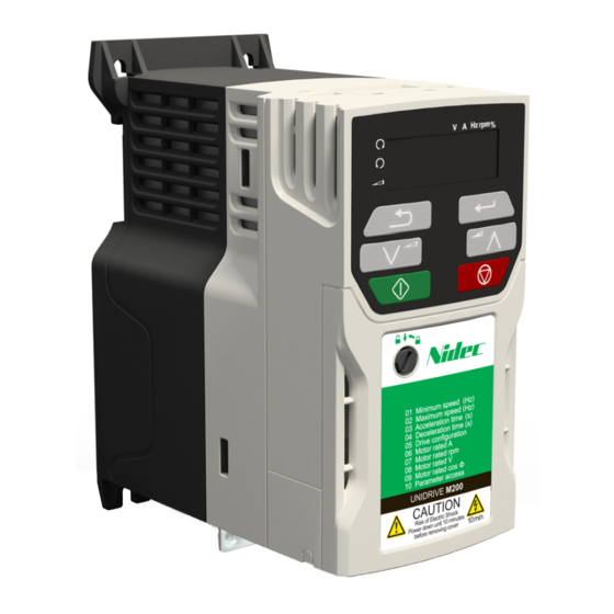
Figure 3-1 Feature diagram (size 2 shown) 1. Rating label (On side of drive) 2. Identification label 3. Relay connections 4. Control connections 5. Braking terminal 6. Internal EMC filter screw 7. DC bus + 8. DC bus - 9. Motor connections 10. -
Page 12: External Braking Resistor
External braking resistor Overload protection When an external braking resistor is used, it is essential that an overload protection device is incorporated in the braking resistor circuit; as shown in the electrical diagram on the back cover. WARNING 4.2.1 Minimum resistance values and peak power rating for the braking resistor at 40 °C (104 °F) Table 4-1 Braking resistor resistance and power rating (100 V) Minimum... -
Page 13: Ground Leakage
Table 4-3 Braking resistor resistance and power rating (400 V) Minimum Instantaneous Continuous Model resistance* power rating power rating Ω 02400013 0.37 02400018 0.55 02400023 0.75 02400032 02400041 03400056 03400073 03400094 04400135 11.2 04400170 * Resistor tolerance: ±10 % Ground leakage The ground leakage current depends upon whether the internal EMC filter is installed or not. -
Page 14: Control Terminal Configurations And Wiring
Size 4: < 1 mA The above leakage currents are just the leakage currents of the drive and do not take into NOTE account any leakage currents of the motor or motor cable. When the internal filter is installed the leakage current is high. In this case a permanent fixed ground connection must be provided, or other suitable measures taken to prevent a safety hazard occurring if the connection is lost. - Page 15 Value Text Description Analog input 1 (voltage) or Analog input 2 (voltage) selected by terminal (Local/Remote) Analog input 1 (current) or Analog input 2 (voltage) selected by terminal (Local/Remote) AV.Pr Analog input 1 (voltage) or 3 presets selected by terminal AI.Pr Analog input 1 (current) or 3 presets selected by terminal PrESEt Four presets selected by terminal...
- Page 16 Figure 4-2 Pr 05 = AI Current speed Current speed reference reference input input (AI 1) + 10 V output Voltage speed reference input (AI 2) Analog output 1 (motor frequency) + 24 V output Digital output (zero frequency) Drive enable Run forward Run reverse Analog input 1/...
- Page 17 Figure 4-4 Pr 05 = AI.Pr Current speed Current speed reference input reference input (AI 1) + 10 V output Reference select Analog output 1 (motor frequency) + 24 V output Digital output (zero frequency) Terminal 5 Terminal 14 Reference selected Drive enable Analog reference 1* Preset speed 2*...
- Page 18 Figure 4-6 Pr 05 = PAd Voltage speed reference input (AI 1) + 10 V output Voltage speed reference input (AI 2) Analog output 1 (motor frequency) When Pr 05 is set to PAd, to run in reverse: Set Pr 17 to On + 24 V output The keypad reference can now be set to a negative frequency to run the motor in the reverse direction.
- Page 19 Figure 4-8 Pr 05 = E.Pot Voltage speed reference input (AI 1) + 10 V output DOWN hen Pr 05 is set to E.Pot, the following parameters may need to be adjusted: • Motorized pot up/down rate (s/100 %)* • Motorized pot bipolar select (0 = unipolar, 1 = bipolar)* •...
-
Page 20: Emc
Figure 4-10 Pr 05 = Pid When Pr 05 is set to Pid, the following parameters may need to be adjusted: 4 - 20 mA PID PID feedback feedback input input (AI 1) • PID proportional gain* • PID integral gain* + 10 V output •... - Page 21 4.5.2 Removing the internal EMC filter The supply must be disconnected before removing the internal EMC filter. WARNING Figure 4-11 Removal of the internal EMC filter (size 2 shown) To electrically disconnect the internal EMC filter, remove the screw as shown above (1). 4.5.3 Further EMC precautions Further EMC precautions are required if more stringent EMC emission requirements apply:...
-
Page 22: Keypad And Display
Keypad and display The keypad and display provide information to the user regarding the operating status of the drive, alarms and trip codes, and provide the means for changing parameters, stopping and starting the drive, and the ability to perform a drive reset. Figure 5-1 Unidrive M200 keypad detail Figure 5-2 Unidrive M201 keypad detail V A Hz rpm %... -
Page 23: Saving Parameters
Saving parameters When changing a parameter in Menu 0, the new value is saved when pressing the Enter button to return to parameter view mode from parameter edit mode. If parameters have been changed in the advanced menus, then the change will not be saved automatically. -
Page 24: Basic Parameters (Menu 0)
Basic parameters (Menu 0) Menu 0 is used to bring together various commonly used parameters for basic easy set up of the drive. Menu 0: Basic parameters Range Default () () Parameter Type RFC-A RFC-A Minimum Speed 0.00 to Pr 02 Hz 0.00 Hz RW Num Def.50: 50.00 Hz... - Page 25 Range Default () () Parameter Type RFC-A RFC-A Ramp Enable Off (0) or On (1) On (1) NonE (0), rEAd (1), Prog (2), Parameter Cloning NonE (0) Auto (3), boot (4) CoASt (0), rP (1), CoASt (0), rP (1), rP.dc I (2), rP.dc I (2), Stop Mode dc I (3), td.dc I (4),...
- Page 26 Range Default () () Parameter Type RFC-A RFC-A Brake Controller Brake Apply Through 0.00 to 25.00 Hz 1.00 Hz RW Num Zero Threshold Brake Controller diS (0), rELAy (1), dig IO (2), diS (0) Enable USEr (3) Trip 0 0 to 255 ND NC PT PS Trip 1 0 to 255...
- Page 27 ** Setting Pr 07 to 0.0 will disable slip compensation. *** Following a rotating autotune, Pr 09 is continuously written to by the drive, calculated from the value of Stator Inductance (Pr 05.025). To manually enter a value into Pr 09, Pr 05.025 will need to be set to 0. Refer to the description of Pr 05.010 in the Parameter Reference Guide for further details.
- Page 28 Figure 6-1 Menu 0 logic diagram Analog Input 1/ Input 2 select Analog Input 1 Analog reference Analog Input Analog Input 1 1 Mode Analog Input 2 Analog Input 2 01.050 01.015 >1 Bipolar Reference Drive Enable Configuration Select Preset frequency reference Preset Reference 1 Preset Reference 2 Preset Reference 3...
- Page 29 RFC-A> FREQUENCY AT ZERO FREQUENCY FORWARD REVERSE Analog output Digital output Reference On Reverse Select Final Demand Pre-ramp Reference Reference Maximum Speed Ramp Enable Minimum Speed Motor parameters RFC-A mode only Rated Current Rated Speed x(-1) Rated Voltage Ramps Power Factor Catch A Spinning Motor RFC-A Speed-loop Rated Frequency...
-
Page 30: Unidrive M200/201 Parameter Descriptions
Unidrive M200/201 parameter descriptions Key: Read / Read Number Binary Text string Filtered Write only parameter parameter parameter Protected Rating Power-down default User save DE Destination copied parameter dependent save value Minimum Speed 0.00 to Pr 02 Hz 0.00 Hz RFC-A Set Pr 01 at the required minimum output frequency of the drive for both directions of rotation. - Page 31 Drive Configuration AV (0), AI (1), AV.Pr (2), AI.Pr (3), PrESEt (4), PAd (5), PAd.rEF (6), AV (0)* E.Pot (7), torquE (8), Pid (9) * With Unidrive M201, the default is PAd (5). Use Pr 05 to select the required frequency/speed reference as follows: Value Text Description...
- Page 32 Motor Rated Speed Def.50: 1500.0 rpm Def.60: 1800.0 rpm 0.0 to 33000.0 rpm Def.50: 1450.0 rpm RFC-A Def.60: 1750.0rpm Set to the rated speed of the motor (taken from the motor name plate). The motor rated speed is used to calculate the correct slip speed for the motor.
- Page 33 Start/Stop Logic Select 0 to 6 RFC-A This parameter changes the functions of the input terminals which are normally associated with the enabling, starting and stopping the drive. Pr 11 Terminal 11 Terminal 12 Terminal 13 Latching Enable Run Forward Run Reverse /Stop...
- Page 34 The table below gives all the possible analog input modes. Value Text Function 4-20.S Stop on loss 20-4.S Stop on loss 4-20.L 4-20 mA switching to equivalent of 4 mA input current on loss 20-4.L 20-4 mA switching to equivalent of 20 mA input current on loss 4-20.H 4-20 mA hold at level before loss on loss 20-4.H...
- Page 35 Status Mode Parameter 2 0.000 to 30.999 4.020 RFC-A This parameter and Status Mode Parameter 1 (Pr 23) define which parameters are displayed in Status mode. The values can be alternated by pressing the Escape key, if the drive is running. Status Mode Parameter 1 ...
- Page 36 Ramp Mode Select Fast (0), Std (1), Std.bst (2), Std (1) Fst.bst (3) RFC-A Defines the mode used by the ramp system. 0: Fast ramp 1: Standard ramp 2: Standard ramp with motor voltage boost 3: Fast ramp with motor voltage boost Fast ramp is linear deceleration at programmed rate, normally used when a braking resistor is installed.
- Page 37 Stop Mode CoASt (0), rP (1), rP.dc I (2), dc I (3), td.dc I (4), dis (5) rP (1) CoASt (0), rP (1), rP.dc I (2), RFC-A dc I (3), td.dc I (4), dis (5), No.rP (6) Defines how the motor is controlled when the run signal is removed from the drive. Value Text Description...
- Page 38 Pr 33 Text Function Disabled Enable Detect all frequencies Fr.Only Detect positive frequencies only Rv.Only Detect negative frequencies only Digital Input 5 Select Input (0), th.Sct (1), th (2), Input (0) th.Notr (3), Fr (4) RFC-A This parameter selects the function of Digital Input 5 (terminal 14). Value Text Function...
- Page 39 Digital Output 1 Control 0 to 21 RFC-A Defines the behaviour of digital output 1 (terminal 10). Value Description User defined by Digital IO1 Source/Destination A Drive running signal Frequency arrived signal Frequency level detection signal Frequency level detection signal Overload detection signal Power off state External fault stop...
- Page 40 Value Description User defined by Analog Output 1 Source A Frequency output Frequency reference Motor speed Current Magnitude Torque output Torque current output Voltage output DC bus voltage (0 to 800 V) Analog Input 1 Analog Input 2 Power output (0 to 2 x Pe) Torque limitation Torque reference (0 to 300 %) Maximum Switching Frequency...
- Page 41 Autotune 0 to 2 RFC-A 0 to 3 Defines the auto-tune test to be performed. There are two autotune tests available in open loop mode, a stationary and a rotating test. A rotating autotune should be used whenever possible so the measured value of power factor of the motor is used by the drive.
- Page 42 Control Mode Ur.S (0), Ur (1), Fd (2), Ur.Auto (3), Ur.I (4) Ur.I (4), SrE (5), Fd.tap (6) RFC-A Defines the drive output mode, which can either be a voltage mode or a current mode. Value Text Description Ur.S Stator resistance and voltage offset measured at each start No measurements...
- Page 43 Serial Address 1 to 247 RFC-A Used to define the unique address for the drive for the serial interface. The drive is always a slave, address 0 is used to globally address all slaves, and so this address should not be set in this parameter.
- Page 44 Brake Controller Brake Release Frequency 0.00 to 20.00 Hz 1.00 Hz RFC-A Defines the Brake Release Frequency. See Brake Controller Brake Release in Parameter Reference Guide. Brake Controller Brake Apply Frequency 0.00 to 20.00 Hz 2.00 Hz RFC-A Defines the Brake Apply Frequency.
- Page 45 Brake Controller Brake Apply Through Zero Threshold 0.00 to 25.00 Hz 1.00 Hz RFC-A Defines if the brake is applied through zero threshold. See Brake Controller Brake Release in Parameter Reference Guide. Brake Controller Enable diS (0), rELAy (1), dig IO (2), ...
- Page 46 OUP Status -2147483648 to 2147483647 RFC-A This parameter indicates the status of the user program in the drive. For further information, refer to the Control User Guide. Frequency Controller Proportional Gain Kp1 RFC-A 0.000 to 200.000 s/rad 0.100 s/rad Defines the proportional gain for frequency controller 1.
- Page 47 Spin Start Boost 0.0 to 10.0 RFC-A Spin Start Boost (Pr 69) is used by the algorithm that detects the frequency of a spinning motor when the drive is enabled and Catch A Spinning Motor (Pr 33) 1. For smaller motors the default value of 1.0 is suitable, but for larger motors, Spin Start Boost (Pr 69) may need to be increased.
- Page 48 PID1 Output Upper Limit 0.00 to 100.00 % 100.00 % RFC-A This parameter with PID1 Output Lower Limit (Pr 75) allows the output to be limited to a range. For further information, refer to the Parameter Reference Guide. PID1 Output Lower Limit ...
- Page 49 User Drive Mode OPEn.LP (1) OPEn.LP (1), RFC-A (2) RFC-A RFC-A (2) Defines the mode of the drive. Reference Selected -Pr 02 to Pr 02 or Pr 01 to Pr 02 Hz RFC-A This is the basic reference selected from the available sources. Pre-ramp Reference ...
- Page 50 Output Frequency ± 550.00 Hz RFC-A Open loop mode: The Output Frequency is the sum of the Post Ramp Reference and the motor slip compensation frequency. RFC-A mode: The output frequency is not controlled directly, but the Output Frequency is a measurement of the frequency applied to the motor.
- Page 51 Digital I/O Read Word 0 to 2047 RFC-A Digital I/O Read Word reflects the state of digital inputs/outputs 1 to 5 and the relay. Reference On Off (0) or On (1) RFC-A Reference On, which is controlled by the drive sequencer, indicates that the reference from the reference system is active.
-
Page 52: Running The Motor
Running the motor This section takes a new user through all the essential steps to running a motor for the first time. Table 7-1 Open Loop and RFC-A Action Detail Ensure: • The drive enable signal is not given, terminal 11 is open •... -
Page 53: Diagnostics
Action Detail Ready to run The drive is now ready to run the motor.Close the Run Forward or Run Reverse terminals on Unidrive M200; press keypad Start button on M201. Changing the selected Analog frequency reference (Speed Ref Increasing and Potentiometer on M201) will increase and decrease the speed decreasing speed of the motor. - Page 54 Trip Condition Description code Current loss was detected in current mode on Analog input 1 cL.A1 Analog input 1 current loss (Terminal 2). Initiated by setting bit 12 on the control word when the control CL.bt Trip initiated from the Control Word word is enabled.
- Page 55 Trip Condition Description code The instantaneous drive output current has exceeded.The set limit. Possible solutions: • Increase acceleration/deceleration rate Instantaneous output over current • If seen during autotune reduce the voltage boost OI.AC detected • Check for short circuit on the output cabling •...
- Page 56 Trip Condition Description code Option module in option slot 1 has Option module in option slot 1 on the drive has detected an SL.Er detected a fault error. SL.HF Option module 1 hardware fault Option slot 1 on the drive has indicated a hardware fault. Option module in option slot 1 has The option module in option slot 1 on the drive has been SL.nF...
-
Page 57: Alarm Indications
Alarm indications In any mode, an alarm is an indication given on the display by alternating the alarm string with the drive status string display. If an action is not taken to eliminate any alarm except "tuning”, the drive may eventually trip. Alarms are not displayed when a parameter is being edited. Table 8-2 Alarm indications Alarm string Description... - Page 58 Figure 9-2 Basic NV Media Card operation Programs all drive parameters to the Drive reads all NV Media Card parameters from NOTE the NV Media Card Overwrites any data already in data block 1 = rEAd + = Prog + Drive boots from the Drive automatically NV Media Card on...
-
Page 59: Machine Control Studio
Machine Control Studio Machine Control Studio programming software powered by CODESYS Machine Control Studio software provides a flexible and intuitive environment for programming Unidrive M's new automation and motion control features. This new software offers programming for the Unidrive M200's onboard PLC (not available on Unidrive M201). Machine Control Studio is powered by CODESYS, the leading open software for programmable machine control. -
Page 60: Ul Listing Information
UL listing information 11.1 UL file reference All models are UL Listed to both Canadian and US requirements. The UL file reference is: NMMS/ 7.E171230. 11.2 Option modules, kits and accessories Option Modules, Control Pods, Installation Kits and other accessories for use with these drives are UL Listed. -
Page 61: Motor Overload Protection And Thermal Memory Retention
BRANCH CIRCUIT PROTECTION The fuses and circuit breakers required for branch circuit protection are specified in the Installation Instructions. OPENING OF BRANCH CIRCUIT Opening of the branch-circuit protective device may be an indication that a fault has been interrupted. To reduce the risk of fire or electric shock, the equipment should be examined and replaced if damaged. - Page 62 Quick start setup using default parameter settings Digital I/O Analog I/O 24 V user Analog input 1+ Digital I/O1 Frequency Zero frequency reference 1 10 V user Digital Input 2 Drive enable Digital input 3 Analog input 2 Frequency Run forward reference 2 Digital input 4 Analog output 1...
Need help?
Do you have a question about the Unidrive M201 Series and is the answer not in the manual?
Questions and answers