Advertisement
Quick Links
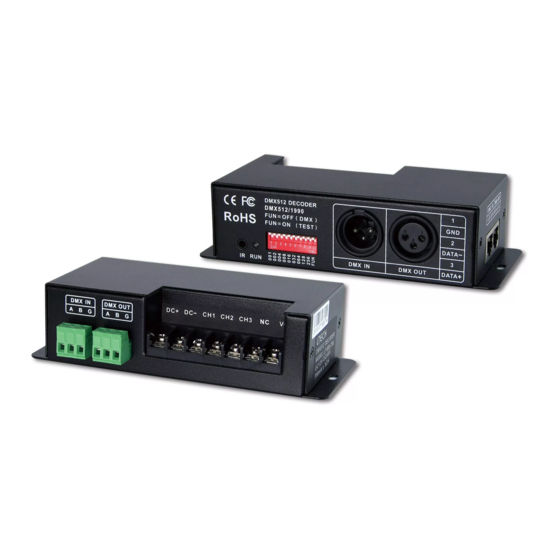
LT-840-700
DMX/RDM 4CH CC DECODER
LT-840-700 w
ith the standard RDM remote device management protocol, supports DMX512 signal
bi-directional communication, achieves remote management of reading and writing DMX address
(DMX master controller must recognize the RDM protocol). Equipped with DMX standard 3-pin XLR,
RJ45, green terminal interface. Realize
0-100% dimming or different lighting effect; workable with
single color, dual color, RGB or RGBW/Y LED lamps.
1. Product Parameter:
LT-840-700
Input Signal:
DMX512, RDM
Input Voltage:
12~48Vdc
Output Voltage:
3-46Vdc
Current Load:
CC 700mA×4CH
Output Power:
(2.1W~32.2W)×4CH Max. 128.8W
DMX512 Socket:
3-pin XLR, RJ45, Green Terminal
2. Product Size:
78mm
146mm
156mm
3. Configuration Diagram:
Green Terminal
LED Lamps
(with amplifier function)
Connection Socket
Power Input Socket
LT-840 700 DMX/RDM 4CH CC Decoder
-
Dimming Range:
0~100%
Protection:
Short circuit / Over current
Working Temperature:
-30℃~65℃
Dimensions:
L156×W78×H40(mm)
Package Size:
L180×W82×H48(mm)
Weight (G.W.):
445g
40mm
Address
3-pin XLR
RJ45
Dip Switch
1
4.
Dip Switch Operation:
RDM Mode: The
DMX Mode:
Self-testing Mode:
4.1 How to set DMX address via dip switch:
FUN=OFF
(the 10th dip switch
=OFF
)
DMX
DMX address value = the total value of (1-9), to get the place value when in "ON" position,
otherwise will be 0.
E.g.1: Set Initial Address To 32.
E.g.2: Set Initial Address To 37.
001+004+032=37
4.2 Self-testing Mode:
FUN=ON (
the
10th dip switch = ON)
Self-testing Mode
1-9=off
1=on
2=on
3=on
Dip Switch
Self-test
Static
Static
Static
Static
Black
Red
Green
Blue
Function
3 4 5 6 7 8 9 10
1 2
Static
7 Colors
Static
Static
Cyan
Jumping
Green
Yellow
Static
Static
Static
Static
7 Colors
Red
Blue
Purple
W
hite
Smooth
[Attn]
When several dip switches are on, subjected to the highest switch value.
As the figure above shows, the effect will be 7 colors smooth at 7 speed level.
4.3 DMX Dimming Instruction:
Each LT-840 700 DMX decoder occupied 4 DMX
-
addresses when connecting the DMX console.
e.g., the defaulted initial address is 1, please find
their corresponding relationships in the form.
LT-840 700 DMX/RDM 4CH CC Decoder
-
dip switch 1-10 are OFF.
FUN=OFF ( the 10th dip switch=OFF )
Setting DMX addresses with dip switch 1-9
FUN=ON ( the 10th dip switch=ON )
Mode
E.g.3: Set Initial Address To 178.
002+016+032+128=178
4=on
5=on
6=on
7=on
8=on
Static
Static
Static
Static
7 Colors
Yellow
Purple
Cyan
White
Jumping
OFF
For changing effects (Dip Switch 8 9=on):
/
ON
DIP switch 1-7 is used to realize 7 speed
levels. (7=on, the fastest level)
DMX Console
DMX Decoder
CH1 0-255
CH1
PWM 0-100% (LED R)
CH2 0-255
CH2
PWM
0-100% (
CH3 0-255
CH3
PWM
0-100% (
CH4 0-255
CH4
PWM
0-100% (
2
9=on
7 Colors
Smooth
LED G)
LED B)
LED W/Y)
Advertisement

Related Manuals for Ltech LT-840-700


Summary of Contents for Ltech LT-840-700
- Page 1 (the 10th dip switch =OFF Mode LT-840-700 w ith the standard RDM remote device management protocol, supports DMX512 signal DMX address value = the total value of (1-9), to get the place value when in “ON” position, bi-directional communication, achieves remote management of reading and writing DMX address otherwise will be 0.
- Page 2 3-pin XLR terminal as an example, same connecting method for the rest two: green terminal(with amplifier function) & RJ45 terminal. The LED quantity at each channel can be different; LT-840-700 could auto check AMP interface can be used for signal amplification when too many DMX decoder are connected or signal line is too long, signal and output a proper voltage to each channel according to its LED quantities.
Need help?
Do you have a question about the LT-840-700 and is the answer not in the manual?
Questions and answers