Federal Signal Corporation e-Q2B Manuals
Manuals and User Guides for Federal Signal Corporation e-Q2B. We have 3 Federal Signal Corporation e-Q2B manuals available for free PDF download: Installation Maintenance And Service Manual, Instruction Sheet

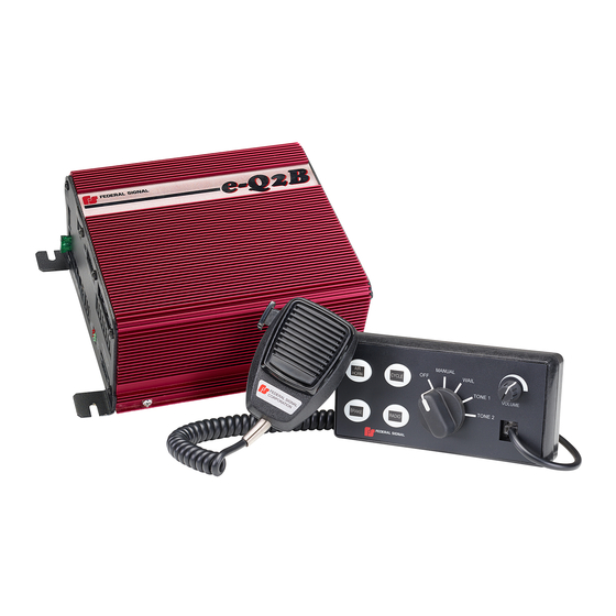
Federal Signal Corporation e-Q2B Installation Maintenance And Service Manual (60 pages)
Electronic Siren System
Brand: Federal Signal Corporation
|
Category: Security System
|
Size: 3 MB
Table of Contents
Advertisement

Federal Signal Corporation e-Q2B Installation Maintenance And Service Manual (60 pages)
Electronic Siren System
Brand: Federal Signal Corporation
|
Category: Security System
|
Size: 3 MB
Table of Contents

Federal Signal Corporation e-Q2B Instruction Sheet (8 pages)
POWER CABLE SERVICE KIT
Brand: Federal Signal Corporation
|
Category: Service Equipment
|
Size: 2 MB
Advertisement
Advertisement
Related Products
- Federal Signal Corporation E1
- Federal Signal Corporation ez1 echo
- Federal Signal Corporation EM3
- Federal Signal Corporation eHorn
- Federal Signal Corporation EOWS-612
- Federal Signal Corporation Electraray 225 Series
- Federal Signal Corporation Equinox
- Federal Signal Corporation Eclipse8
- Federal Signal Corporation 2-120
- Federal Signal Corporation 2-240