Federal Signal Corporation Vision SLR Series Installation Maintenance And Service Manual
3-pod and split lightbars
Hide thumbs
Also See for Vision SLR Series:
- Installation maintenance and service manual (48 pages) ,
- Installation maintenance and service manual (52 pages)

Related Manuals for Federal Signal Corporation Vision SLR Series


Summary of Contents for Federal Signal Corporation Vision SLR Series
- Page 1 3-Pod and Split Vision SLR Lightbars ™ Installation, Maintenance, and Service Manual 2562678A REV. A 212 Printed in U.S.A.
- Page 2 Solaris is a registered trademark of Federal Signal Corp. Vision SLR is a trademark of Federal Signal Corp. Torx is a registered trademarks of Accument Intellectual Properties, LLC Plexis is a registered tradenark of Gaymar Industries, Inc. Opticom is a trademark of Global Traffic Technologies, LLC...
-
Page 3: Table Of Contents
Contents CHAPTER 1 Safety Messages for Installers and Operators ..........5 Safety Messages to Installers of Warning Light Equipment ..............5 Safety Message to Operators of Warning Light Equipment ..............8 CHAPTER 2 An Overview of the 3-Pod and Split Vision Lightbars ........9 LED Lights and Colors ..........................9 LED Flash Rates and Positions .........................9 Control Options ............................9... - Page 4 Contents Contents Table 4.1 Functions of 2-conductor power cable and 6-conductor control cable ........15 Table 5.1 Legends for VSLR flash patterns ....................17 Table 5.2 3-Pod VSLR Flash Patterns ......................18 Table 5.3 6-Pod VSLR Flash Patterns ......................19 Table 5.4 8-Pod VSLR Flash Patterns ......................20 Table 6.1 Troubleshooting tips ........................29 Table 6.2 Replacement parts ........................30 Figures...
-
Page 5: Chapter 1 Safety Messages For Installers And Operators
CHAPTER 1 Safety Messages for Installers and Operators For your safety, read and understand this manual thoroughly before installing, operating, and servicing the Vision SLR lightbar. The safety messages presented in this chapter and throughout the manual are ™ reminders to exercise extreme care at all times. In addition, read and understand the safety instructions to installers (doc. - Page 6 Chapter 1: Safety Messages for Installers and Operators Electrical Hazards • A light system is a high current system. In order for the system to function properly, a separate negative (–) connection and positive (+) connection must be made. All negative connections should be connected to the negative battery terminal and a suitable fuse should be installed on the positive battery terminal connection as close to the battery as possible.
- Page 7 Chapter 1: Safety Messages for Installers and Operators • When drilling into a vehicle structure, be sure that both sides of the surface are clear of anything that could be damaged. Remove all burrs from drilled holes. To prevent electrical shorts, grommet all drilled holes through which wiring passes.
-
Page 8: Safety Message To Operators Of Warning Light Equipment
Chapter 1: Safety Messages for Installers and Operators Safety Message to Operators of Warning Light Equipment People’s lives depend on your safe use of our products. Listed below are some important safety instructions and precautions you should follow: • Do not attempt to activate or de-activate the light system control while driving in a hazardous situation. -
Page 9: Chapter 2 An Overview Of The 3-Pod And Split Vision Lightbars
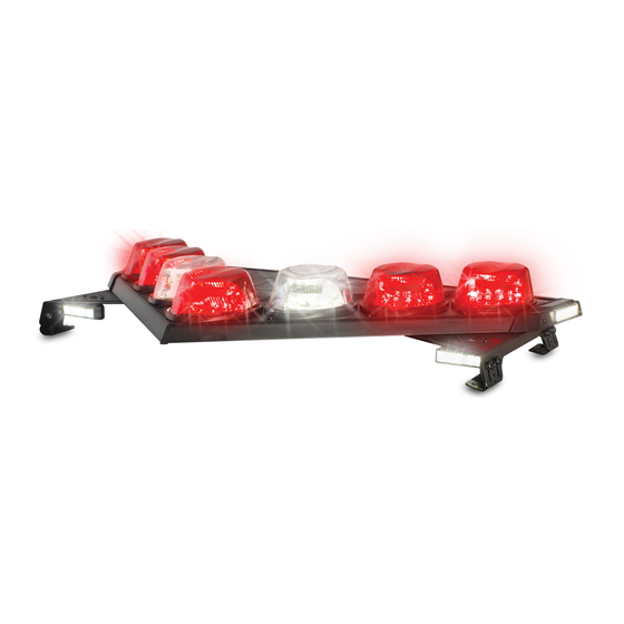
CHAPTER 2 An Overview of the 3-Pod and Split Vision Lightbars The 3-Pod and Split Vision SLR are rotating LED lightbars, employing fixed LED boards and rotating Solaris ® S2 reflectors. V-shaped construction lets the Vision SLR warning system maximize light warning efficiency at crucial intersection angles. -
Page 10: Dimensions
Chapter 2: An Overview of the 3-Pod and Split Vision SLR Lightbars Dimensions Model Length Height Depth Weight* VSLR3 22.4 in (56.9 cm) 4.6 in (11.7 cm) 17.8 in (45.2 cm) 21.6 lb (9.8 kg) VSLR6 (each half) 21.1 in (53.6 cm) 4.6 in (11.7 cm) 21.7 in (55.1 cm) 18.9 lb (8.6 kg) -
Page 11: Chapter 3 Preparing For The Lightbar Installation
CHAPTER 3 Preparing for the Lightbar Installation Taking the preparatory steps in this chapter before mounting and wiring the lightbar to a vehicle will help ensure that your installation is fast, easy, and error free. Unpacking the Lightbar HEAVY OBJECT—Use lifting aids and proper lifting techniques when removing or replacing this product. - Page 12 Chapter 1: Preparing for the Lightbar Installation SEAT REMOVAL PRECAUTION—If a vehicle seat is temporarily removed, verify with the vehicle manufacturer if the seat needs to be recalibrated for proper airbag deployment. Failure to follow this warning cause serious injury or death. To make wiring easier, remove the seats, spare tire, and pull down the headliner where needed.
-
Page 13: Chapter 4 Wiring The Lightbar In The Vehicle
CHAPTER 4 Wiring the Lightbar in the Vehicle Before wiring the lightbar in the vehicle, ensure that the lightbar has been installed on the vehicle roof in accordance with the instructions included with the mounting kit. Installation of options such as an Opticom require additional wiring to the warning light system and vehicle battery not covered in this ®... -
Page 14: Wiring The Control Cable For The Standard Vslr Lightbar
Chapter 4: Wiring the Lightbar in the Vehicle CURRENT CAPABILITY—To provide safe operation of the lightbar, the power control switch and wiring must be capable of handling the rated current of the fuse at the source. HIGH CURRENT ARCING—Do not connect this system to the vehicle battery until ALL other electrical connections are completed, the mounting of all components is complete, and you have verified that no shorts exist. -
Page 15: Wiring The Controls For White Light And Rear Light Cutoff
Chapter 4: Wiring the Lightbar in the Vehicle Table 4.1 Functions of 2-conductor power cable and 6-conductor control cable Wire Color Function PRIMARY MODE: +12 Vdc activates the lightbar in Primary Mode. Black GND (–): Connects to a good battery/chassis ground. Gray FLOOD: Applying +12 Vdc will turn any rotating white heads into a flood light if the lightbar is powered up in Primary or Secondary Mode. -
Page 16: Chapter 5 Programming Flash Patterns
CHAPTER 5 Programming Flash Patterns Although the standard VSLR lightar is shipped with preselected flash patterns for Primary and Secondary Mode, you can select new patterns from the lightbar's internal library of flash patterns. A pattern displayed in Primary Mode is typically more active than the pattern displayed in Secondary Mode. It indicates the primary purpose of the vehicle;... -
Page 17: Programming Secondary Mode
Chapter 5: Programming Flash Patterns Programming Secondary Mode For flash patterns in the lightbar library, refer to the table for your model of lightbar. LIGHT HAZARD—To be an effective warning device, this product produces bright light that can be hazardous to your eyesight when viewed at a close range. - Page 18 Chapter 5: Programming Flash Patterns Table 5.2 3-Pod VSLR Flash Patterns Pattern Pod 1 Pod 2 Pod 3 OSC F OSC F OSC FL OSC F OSC FR OSC FL OSC FR OSC F OSC F OSC FL OSC FR OSC F OSC F OSC F...
- Page 19 Chapter 5: Programming Flash Patterns Table 5.3 6-Pod VSLR Flash Patterns Pattern Pod 1 Pod 2 Pod 3 Pod 4 Pod 5 Pod 6 OSC L OSC F OSC F OSC R * & ** OSC L OSC F OSC F OSC R * &...
- Page 20 Chapter 5: Programming Flash Patterns Table 5.4 8-Pod VSLR Flash Patterns Pattern Pod 1 Pod 2 Pod 3 Pod 4 Pod 5 Pod 6 Pod 7 Pod 8 OSC L OSC F OSC F OSC R * & ** OSC L OSC F OSC F OSC R...
-
Page 21: Chapter 6 Maintaining And Servicing The Lightbar
CHAPTER 6 Maintaining and Servicing the Lightbar This chapter describe how to maintain and service the Vision SLR lightbar. Establishing a regular maintenance and inspection schedule extends the life of the lightbar and ensures safety. For service, support, or replacement parts, contact the Federal Signal Service Department at 1-800-433-9132, 7 a.m. to 5 p.m, Monday through Friday (CT). -
Page 22: Replacing A Dome
Chapter 6: Maintaining and Servicing the Lightbar that is non-abrasive or a plastic polish like Plexus ® Replacing a Dome The lightbar domes filter the LED lights and protect the LED and circuitry. If a dome is damaged, it must be replaced. -
Page 23: Replacing A Pod
Chapter 5: Maintaining and Servicing the Lightbar Installing a Dome To install a dome: DO NOT FORCE THE DOME DOWNWARD—If there is resistance to the dome dropping into position on the base, do not force it downward. To avoid damaging the dome, ensure that the dome hook is properly centered with the mating recess in the pod base so that it drops down from the vertical position. -
Page 24: Figure 6.2 Pods Rotated For Removal
Chapter 6: Maintaining and Servicing the Lightbar Figure 6.2 Pods rotated for removal #10-32 x 1/4" TORX SHOULDER SCREW ROTATE CLOCKWISE ROTATE COUNTER- TO THE STOPPING POINT CLOCKWISE INDICATED BY POD 5 TO THE STOPPING POINT INDICATED BY POD 1 Installing a Pod To install a pod: Reconnect the electrical connector to the pod. -
Page 25: Replacing A Lightbar Controller
Chapter 5: Maintaining and Servicing the Lightbar Replacing a Lightbar Controller The lightbar controller controls the flash patterns and auxiliary light functions. If a lightbar problem cannot be traced to a pod, a wiring connection, or the vehicle battery, the problem may lie with the controller. -
Page 26: Figure 6.3 Location Of Vslr3 Pcba
Chapter 6: Maintaining and Servicing the Lightbar Figure 6.3 Location of VSLR3 PCBA DRIVER SIDE (BOTTOM) PCBA INSTALLED PASSENGER DRIVER SIDE SIDE (TOP) SIDE (TOP) POD 3 POD 2 POD 1 SWITCH SETTINGS FOR 3-POD VSLR3 BOTTOM VIEW 290A6892 3-Pod and Split Vision SLR Lightbars... -
Page 27: Figure 6.4 Location Of Vslr3 Pcba
Chapter 5: Maintaining and Servicing the Lightbar Figure 6.4 Location of VSLR3 PCBA PASSENGER SIDE DRIVER SIDE (BOTTOM) (BOTTOM) PCBA INSTALLED PCBA INSTALLED PASSENGER DRIVER SIDE SIDE (TOP) SIDE (TOP) POD 3 POD 4 POD 6 POD 2 POD 5 POD 1 SWITCH SETTINGS SWITCH SETTINGS... -
Page 28: Figure 6.5 Location Of Vslr8 Pcba
Chapter 6: Maintaining and Servicing the Lightbar Figure 6.5 Location of VSLR8 PCBA PASSENGER SIDE DRIVER SIDE (BOTTOM) (BOTTOM) PCBA INSTALLED PCBA INSTALLED PASSENGER DRIVER SIDE SIDE (TOP) SIDE (TOP) POD 4 POD 8 POD 1 POD 5 POD 7 POD 3 POD 2 POD 6... -
Page 29: Troubleshooting The Lightbar
Getting Technical Support and Service Federal Signal Corporation will service your equipment or provide technical assistance with any problems that cannot be handled locally. Any product returned to Federal Signal for service, inspection, or repair must be accompanied by a Return Material Authorization number. The RMA number can be obtained from your local distributor or Federal Signal. -
Page 30: Ordering Replacement Parts
Chapter 6: Maintaining and Servicing the Lightbar Ordering Replacement Parts To order replacement parts, please contact your local dealer/distributor or: Customer Support Federal Signal Corporation Phone: 1-800-264-3578 (7 a.m. to 5 p.m., Monday through Friday, Central Time) Table 6.2 Replacement parts... - Page 31 Chapter 5: Maintaining and Servicing the Lightbar Federal Signal Corporation Public Safety Systems 2645 Federal Signal Drive University Park, IL 60484-3167 Attn: Service Department RMA: #__________ www.fedsig.com Tel.: (800) 264-3578 • Fax: (800) 682-8022 3-Pod and Split Vision SLR Lightbars...
- Page 32 2645 Federal Signal Drive, University Park, IL 60484-3167 Tel.: (800) 264-3578 • Fax: (800) 682-8022 www.fedsig.com © 2012 Federal Signal Corporation...
Need help?
Do you have a question about the Vision SLR Series and is the answer not in the manual?
Questions and answers