Table of Contents
Advertisement
Quick Links
Advertisement
Table of Contents

Related Manuals for FLIR TG275


Summary of Contents for FLIR TG275
- Page 1 USER MANUAL Automotive Diagnostic Thermal Camera Model TG275...
- Page 3 USER MANUAL Automotive Diagnostic Thermal Camera #NAS100009; r. AJ/63868/63869; en-US...
-
Page 5: Table Of Contents
Bluetooth® Communication and FLIR Tools™ ...... 18 Bluetooth® Communication Overview......18 Download the FLIR Tools™ Mobile App......18 Setting up the FLIR Tools™ Mobile App......18 Transmit Images via Bluetooth® ........18 FCC Compliance ............20 Field Firmware Updates ............. 22 System Firmware Update ........... - Page 6 Table of contents Specifications..............24 10.1 Imaging and Optical Specifications ....... 24 10.2 Detector Specifications ..........24 10.3 Image Presentation Specifications........ 24 10.4 Measurement Specifications ........25 10.5 Measurement Analysis Specifications ......25 10.6 Configuration Specifications........25 10.7 Image Storage Specifications ........26 10.8 Digital Camera ............
-
Page 7: Advisories
The documentation must not, in whole or part, be copied, photocopied, repro- duced, translated or transmitted to any electronic medium or machine-read- able form without prior consent, in writing, from FLIR Systems. Names and marks appearing on the products herein are either registered trademarks or trademarks of FLIR Systems and/or its subsidiaries. -
Page 8: Introduction
Register the TG275 within 60 days to activate the 2–10 Year Warranty Extension at this link: https://support.flir.com/prodreg. Features •... -
Page 9: Safety
Safety 3.1 Safety Warnings and Cautions WARNING ⚠ This symbol, adjacent to another symbol indicates the user must refer to the manual for further information. WARNING The instrument’s IP54 rating is only in affect when the top flap (covering the USB-C jack) is completely sealed. -
Page 10: Description
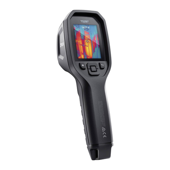
Description 4.1 Product Description Figure 4.1 Imaging IR Thermometer Description 1. Display area 2. Return button (to back up in the menu system) 3. Laser pointer button 4. Up/Down Navigation buttons & Power (long press)/Menu (short press) button 5. Lanyard post 6. -
Page 11: Control Button Descriptions
Press to activate the Laser pointer Pull trigger to capture camera image TRIGGER Pull trigger to exit the menu system 4.3 Display Description Figure 4.2 TG275 Displays 1. Menu area 2. Date and time 3. Batter status percentage 4. Battery status indicator 5. - Page 12 Description 6. USB connection active 7. Camera image area 8. Center spot cross-hairs 9. Laser Pointer active 10. Center spot temperature measurement #NAS100009; r. AJ/63868/63869; en-US...
-
Page 13: Operation
(not supplied) using the supplied USB-C cable. The USB-C jack is located in the compartment at the top of the TG275. Do not use the TG275 while it is charging. When the top flap is closed, the TG275 is rated IP54 for encapsula- tion. -
Page 14: High Temperature Switch
TG275 display. 4. Use the Laser pointer to accurately target a spot. Press the Laser pointer button to switch ON the Laser pointer. The TG275 Laser pointer includes a circular spot indicating the area that is being monitored for temperature, utilizing DOE (Diffractive Optical Elements) technology. -
Page 15: Visible Spectrum Camera
5. To transfer images to a PC, connect the TG275 to a PC using the supplied USB-C cable. The USB jack is located at the top of the TG275 under the flap. -
Page 16: Programming Menu System
DELETE/DELETE ALL FILES menu. Select SEND to transmit the selected image to a paired mobile device (see Section 7, Bluetooth® Communica- tion and FLIR Tools™, for more information). • IMAGE ADJUSTMENTS: Press MENU to access IMAGE MODES (includ- ing MSX® alignment) and colors, see below:... - Page 17 Programming Menu System 1. Image Modes: Press MENU at IMAGE MODES and use the arrow buttons to select VISIBLE IMAGE or THERMAL PLUS VISIBLE IMAGE (MSX®). 2. MSX® Alignment: Adjust the alignment (so that the thermal image and the visible image line up accurately) as follows: While viewing the THERMAL PLUS VISIBLE IMAGE screen in the menu, press MENU to access the MSX®...
-
Page 18: Settings Sub-Menu
Programming Menu System 3. Colors: Press MENU at the colors menu and use the arrow buttons to se- lect a color palette: Iron, Rainbow, White hot, Black hot, Arctic, or Lava. Press MENU to confirm selection. • SETTINGS: Press MENU to access the Settings sub-menu (see below): 6.3 SETTINGS Sub-Menu •... - Page 19 Programming Menu System 1. Center Spot: Press MENU to enable/disable the display cross-hairs. The cross-hairs should be used as a reference only to identify the spot that is being measured for temperature. Use the Laser pointer for more accurate targeting. 2.
- Page 20 Programming Menu System 1. Bluetooth®: Press MENU to switch Bluetooth® ON or OFF. See Section 7, Bluetooth® Communication and FLIR Tools™, for details. 2. Laser: Press MENU to enable/disable the Laser pointer. When enabled, you can use the Laser pointer button to switch ON the Laser pointer. Use the Laser pointer for accurate targeting of measurement spots.
- Page 21 Programming Menu System 4. Auto Power OFF (APO): Use the arrows to scroll and MENU to select the desired APO time (5/15/30 minutes). Set to ‘Never’ to disable APO. • GENERAL SETTINGS 1. Temperature Unit: Use the arrows and the MENU button to select °C or °F. 2.
- Page 22 Programming Menu System 3. Language: Use the arrows to scroll and the MENU button to select a language. 4. System Info: Scroll to desired topic: Model Number, Serial Number, Software Level, Revision, Battery status (%), and remaining Internal Storage Capacity. •...
- Page 23 Programming Menu System • FACTORY RESET: Follow the prompts to reset the User Settings back to Factory Default status. #NAS100009; r. AJ/63868/63869; en-US...
-
Page 24: Bluetooth® Communication And Flir Tools
The TG275, when paired with a mobile device running the FLIR Tools™ App (using the METERLiNK® protocol), continually transmits readings for live dis- play on the mobile device. You can also send images, stored on the TG275, to your mobile device. - Page 25 Bluetooth® Communication and FLIR Tools™ Figure 7.1 Pairing the TG275 with a Mobile Device Figure 7.2 Sending Images to a Mobile Device #NAS100009; r. AJ/63868/63869; en-US...
-
Page 26: Fcc Compliance
Bluetooth® Communication and FLIR Tools™ Figure 7.3 Viewing Transferred Images on a Mobile Device 7.5 FCC Compliance This device complies with part 15 of the FCC Rules. Operation is subject to the following two conditions: 1. This device may not cause harmful interference. - Page 27 Bluetooth® Communication and FLIR Tools™ 4. Consult the dealer or an experienced radio/TV technician for help. WARNING Changes or modifications not expressly approved by the party responsible for compliance could void the user’s authority to operate the equipment. #NAS100009; r. AJ/63868/63869; en-US...
-
Page 28: Field Firmware Updates
USB-C cable) to transfer the file to the TG275. Firmware updates are available from https://support.flir.com. NOTE The TG275 is not 100% compatible with USB-C to USB-C cables. Use only USB-C to USB-A cables. The supplied cable is USB-C to USB-A. To update the firmware, you will need: •... -
Page 29: Maintenance
90% power requires 4 hours. Charging through a PC USB port is not recommended. If the TG275 is not going to be used for an extended period (> 3 months), it should be charged to at least 70%, stored at room temperature, and re- charged every 6 months. -
Page 30: Specifications
Specifications 10.1 Imaging and Optical Specifications IR resolution 160 x 120 pixels Digital image enhancement Included Thermal Sensitivity /NETD < 70 mK Field of View (FOV) 57° x 44° Minimum focus distance 0.89 ft. (0.3 m) 30:1 Distance-to-Spot ratio Dual range operation Range 1: <... -
Page 31: Measurement Specifications
Specifications 10.4 Measurement Specifications Object temperature range -13 ~ 1022℉ (-25 ~ 550℃) Accuracy at ambient temperature: 59 ~ -13℉ ~ 32℉ (-25℃ to 0℃): ± 7.0℉ (± 95℉ (15 ~ 35℃) 3.0℃) 32℉ ~ 122℉ (0℃ ~ 50℃): ± 5℉ (±2.5℃) 122℉... -
Page 32: Image Storage Specifications
Specifications 10.7 Image Storage Specifications Storage media eMMC 4G Image storage capacity 50k images Image file format JPEG with spot temperature metadata tag 10.8 Digital Camera Resolution 2M pixels Focus Fixed Field of View (FOV) 71° x 56° (adapts to IR lens) 10.9 Flashlight Specifications Flashlight type Bright LED... -
Page 33: Rechargeable Battery Specifications
4.5 hours with Laser ON (medium bright- ness setting) Battery charge life 30 days minimum Charging system Battery is charged inside the TG275 Charging time 4 hours to 90% and 6 hours to 100% Power management APO adjustable 5/15/30 minutes. Can be disabled. -
Page 34: Physical Specifications
Size (L x W x H) 8.3 x 2.5 x 3.2 in. (210 x 64 x 81 mm) Accessory mount UNC ¼”-20 10.15 Included Equipment Standard equipment TG275, USB-C cable, printed Quick Start, Lanyard, Carry Pouch #NAS100009; r. AJ/63868/63869; en-US... -
Page 35: 11 2-10 Extended Warranty
Otherwise, the standard one-year warranty will be in affect from date of purchase. The 2–10 warranty covers parts and labour for the camera for 2 years and coverage of the detector for 10 years. Register your product at https://support.flir.com/prodreg. #NAS100009; r. AJ/63868/63869; en-US... -
Page 36: Customer Support
Customer Support Repair, Calibration, and Technical Support: https://support.flir.com. 12.1 Corporate Headquarters FLIR Systems, Inc. 27700 SW Parkway Avenue Wilsonville, OR 97070, USA #NAS100009; r. AJ/63868/63869; en-US... - Page 38 Customer support http://support.flir.com Copyright © 2020, FLIR Systems, Inc. All rights reserved worldwide. Disclaimer Specifications subject to change without further notice. Models and accessories subject to regional market considerations. License procedures may apply. Products described herein may be subject to US Export Regulations.
Need help?
Do you have a question about the TG275 and is the answer not in the manual?
Questions and answers