Table of Contents
Advertisement
User Manual of Product 1:
FLIR TG267 Thermal Camera, Ideal for Commercial Electrical,
Facility Maintenance, and HVAC Applications, Brilliant 2.4 Inch
Screen, Record Images to Monitor Maintenance History
User Manual of Product 2:
General Tools MMD4E Digital Moisture Meter, Water Leak
Detector, Moisture Tester, Pin Type, Backlit LCD Display With
Audible and Visual High-Medium-Low Moisture Content Alerts,
Grays
Advertisement
Chapters
Table of Contents

Related Manuals for FLIR TG297


Summary of Contents for FLIR TG297
- Page 1 User Manual of Product 1: FLIR TG267 Thermal Camera, Ideal for Commercial Electrical, Facility Maintenance, and HVAC Applications, Brilliant 2.4 Inch Screen, Record Images to Monitor Maintenance History User Manual of Product 2: General Tools MMD4E Digital Moisture Meter, Water Leak...
- Page 2 USER MANUAL Automotive Diagnostic Thermal Camera Models TG267 and TG297...
- Page 4 USER MANUAL Automotive Diagnostic Thermal Camera #NAS100014; r. AA/59807/59807; en-US...
-
Page 6: Table Of Contents
Programming Menu System ..........12 Menu System Basics ..........12 Main Menu .............. 12 Settings Sub-Menu ........... 14 Bluetooth® Communication and FLIR Tools™ ...... 20 FCC Compliance ............20 Field Firmware Updates ............. 22 System Firmware Update ........... 22 Maintenance ..............23 Cleaning .............. - Page 7 Table of contents 10.4 Measurement Specifications ........25 10.5 Measurement Analysis Specifications ......25 10.6 Type-K specifications (TG267 only) ......25 10.7 Configuration Specifications........26 10.8 Image Storage Specifications ........26 10.9 Digital Camera Specifications........26 10.10 Flashlight Specifications..........26 10.11 Laser Pointer Specifications ........
-
Page 8: Advisories
Advisories 1.1 Copyright ©2019, FLIR Systems, Inc. All rights reserved worldwide. No parts of the software including source code may be reproduced, transmitted, transcribed or translated into any language or computer language in any form or by any means, electronic, magnetic, optical, manual or otherwise, without the prior written permission of FLIR Systems. -
Page 9: Introduction
The FLIR TG267 adds Type-K thermocouple contact temperature measurements. The FLIR TG297 offers a high temperature range to 1886℉ (1080℃). Visit https://support.flir.com/prodreg to register your instrument and to extend the standard one-year warranty to the 2-10 Year Warranty. -
Page 10: Safety
Safety 3.1 Safety Warnings and Cautions WARNING ⚠This symbol, adjacent to another symbol indicates the user must refer to the manual for further information. WARNING The instrument’s IP54 rating is only in affect when the top flap (covering the USB-C and Thermocouple jacks) is completely sealed. -
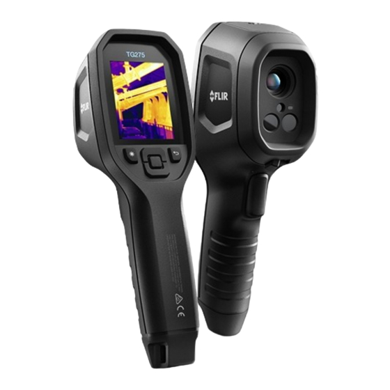
Page 11: Description
Description 4.1 Product Description Figure 4.1 Imaging IR Thermometer Description (TG297 pictured) 1. Display area 2. Return button (to back up in the menu system) 3. Laser pointer button 4. Up/Down Navigation buttons and Power button (long press)/Menu button (short press) 5. -
Page 12: Control Button Descriptions
Description 4.2 Control Button Descriptions Long press to power ON or OFF Short press to access the menu system Return button. Back out to previous screen in menus Press to scroll upward in the menus Press to scroll downward in the menus Press to activate the Laser pointer Pull trigger to capture camera image TRIGGER... - Page 13 Description 7. Camera image area 8. Center spot cross-hairs 9. Laser Pointer active 10. Center spot temperature measurement 11. Thermocouple measurement (TG267) #NAS100014; r. AA/59807/59807; en-US...
-
Page 14: Operation
Operation 5.1 Camera Power Power is supplied by a rechargeable lithium battery. Long press the power button (center) to switch the camera ON or OFF. If the camera does not power ON, charge the battery by connecting to an AC wall charger using the sup- plied USB-C cable. -
Page 15: High Temperature Switch (Tg297)
Figure 5.2 Laser pointer with temperature measurement spot 5.3 High Temperature Switch (TG297) 1. To access the high temperature mode of the TG297, slide the lever to the right (to expose the red color code). 2. The lever is located directly below the lens area and above the image cap- ture trigger. - Page 16 Operation WARNING To avoid electrical shock, do not use this instrument when working near voltages > 24V AC/DC. Do not allow the thermocouple to touch live circuitry. WARNING To avoid damage and burns, do not make temperature measurements in microwave ovens. CAUTION Repeated flexing can break the thermocouple leads.
-
Page 17: Visible Spectrum Camera
Operation 5. If the thermocouple is not connected when the Type-K mode is selected, the display will show dashes in place of a reading. If the measurement is out of range, the display will show ‘OL’. 6. To find the optimum emissivity setting for a given surface, take an IR tem- perature measurement and then take a Type-K measurement. - Page 18 Operation 4. To send/view/delete images, access the Gallery mode in the main menu. In the Gallery, scroll through the stored images with the arrows and open an image with the MENU button. Once an image is opened, press MENU again to see the SEND/CANCEL/DELETE/DELETE ALL IMAGES menu. Select the SEND command to transmit an image, via Bluetooth®, to a paired mobile device.
-
Page 19: Programming Menu System
Programming Menu System 6.1 Menu System Basics Short press the MENU button to access the menu system. Use the MENU button to switch settings ON or OFF, use the Return button to move to the pre- vious screen, and use the arrows to scroll. The MENU button is used in some cases to confirm settings. - Page 20 Programming Menu System 1. Image Modes: Press MENU at IMAGE MODES and use the arrow buttons to select VISIBLE IMAGE or THERMAL PLUS VISIBLE IMAGE (MSX®). 2. MSX® Alignment: While at the Image Mode menu you can adjust the MSX® alignment so that the thermal image and the visible image are aligned accurately.
-
Page 21: Settings Sub-Menu
Programming Menu System 3. Colors: Press MENU at the Colors menu and use the arrow buttons to se- lect a color palette: Iron, Rainbow, White hot, Black hot, Arctic, or Lava. Press MENU to confirm selection. • SETTINGS: Press MENU to access the Settings sub-menu (see below): 6.3 Settings Sub-Menu •... - Page 22 Programming Menu System 1. Center Spot: Press MENU to enable/disable the display cross-hairs. The cross-hairs identify the spot that is being measured for temperature. 2. Emissivity: Press MENU to open the Emissivity adjustment utility. Use the arrows to scroll through the presets (0.95, 0.80, and 0.60) and use the MENU button to select a preset.
- Page 23 Programming Menu System 1. Bluetooth®: Press MENU to switch Bluetooth® ON or OFF. See Section 7, Bluetooth®, and Section 5.6, Capturing and Working with Images, for details. 2. Laser: Press MENU to enable/disable the Laser pointer. When enabled, you can use the Laser pointer button to switch ON the Laser pointer. 3.
- Page 24 Programming Menu System 4. Auto Power OFF (APO): Use the arrows to scroll and MENU to select the desired APO time (5/15/30 minutes). Set to ‘Never’ to disable APO. • GENERAL SETTINGS 1. Temperature Unit: Use the arrows and the MENU button to select °C or °F. 2.
- Page 25 Programming Menu System 3. Language: Use the arrows to scroll and the MENU button to select a language. 4. System Info: Scroll to desired topic: Model Number, Serial Number, Software Level, Revision, Battery status (%), and remaining Internal Storage Capacity. •...
- Page 26 Programming Menu System #NAS100014; r. AA/59807/59807; en-US...
-
Page 27: Bluetooth® Communication And Flir Tools
Bluetooth® Communication and FLIR Tools™ To connect to a mobile device running the FLIR Tools™ Mobile App, turn on the mobile device and start the FLIR Tools™ Mobile App (download the mo- bile App from the Google Play™ store, the Apple App store, or here: https://www.flir.com/products/flir-tools-app/). - Page 28 Bluetooth® Communication and FLIR Tools™ WARNING Changes or modifications not expressly approved by the party responsible for compliance could void the user’s authority to operate the equipment. #NAS100014; r. AA/59807/59807; en-US...
-
Page 29: Field Firmware Updates
System firmware by first downloading an update file from the FLIR website and then transferring the file to the camera via USB. Connect to a PC using a USB-C cable. Firmware updates are available from https://support.flir.com. -
Page 30: Maintenance
Clean the lenses with a high-quality lens cleaner. 9.2 Battery Considerations and Service The rechargeable lithium battery is not user-serviceable. Please contact FLIR support for service instructions: https://support.flir.com. For best results, charge the battery immediately after seeing a low battery in- dication using the supplied USB-C cable (with an AC wall charger, not sup- plied). -
Page 31: Specifications
Field of View (FOV) 57° x 44° Minimum focus distance 0.89 ft. (0.3 m) 30:1 Distance-to-Spot ratio Dual range operation (TG297) Range 1: < 752℉ (400℃) Range 2: > 752℉ (400℃) For Range 2, the high temperature lever must be engaged Focus... -
Page 32: Measurement Specifications
Specifications 10.4 Measurement Specifications Object temperature range TG267: –13 ~ +716℉ (–25 ~ +380℃) TG297: –13 ~ +1886℉ (–25 ~ +1030℃) Accuracy at ambient temperature: 15 ~ -13℉ ~ 32℉ (-25℃ to 0℃): ± 7.0℉ (3.0℃) 35℃ (59 ~95℉) 32℉ ~ 122℉ (0℃ ~ 50℃): ± 5.0℉ or ±... -
Page 33: Configuration Specifications
Please do not exceed the specified range printed on the thermocouple label. To measure higher or lower than the range of the supplied thermocouple, please use a Type-K thermocouple rated for the desired range. Contact FLIR for additional information 10.7 Configuration Specifications... -
Page 34: Laser Pointer Specifications
Specifications Rated power 0.5 W Light output 100 Lumens 10.11 Laser Pointer Specifications Laser type DOE (Diffractive optical elements) Laser function Indicates the size of the measurement area (circular target) Laser class Class I 10.12 Data Communication and Interface Specifications Interfaces USB 2.0 and Bluetooth®... - Page 35 Specifications Operating temperature 14 ~ 113℉ (-10 ~ 45℃) Storage temperature -22 ~ 131℉ (-30 ~ 55℃) Humidity (operating and storage) 0 ~ 90% Relative Humidity (RH) 32 ~ 98.6℉ (0 ~ 37℃) 0 ~ 65% RH 98.6 ~ 113℉ (37 ~ 45℃) 0 ~ 45% RH 113 ~ 131℉...
-
Page 36: Physical Specifications
Specifications 10.15 Physical Specifications Weight 13.9 oz. (0.39 kg) Size (L x W x H) 8.3 x 2.5 x 3.2 in. (210 x 64 x 81 mm) Accessory mount UNC ¼”-20 10.16 Included Equipment Standard equipment Camera, USB-C cable, printed Quick Start Guide, Lanyard, Carry Pouch #NAS100014;... -
Page 37: Appendices
Appendices 11.1 Emissivity Factors for Common Materials Material Emissivity Material Emissivity 0.98 Asphalt 0.90 ~ 0.98 Cloth (black) 0.94 0.98 Concrete Skin (human) 0.96 Leather 0.75 ~ 0.80 Cement 0.90 0.96 Sand Charcoal (powder) 0.92 ~ 0.96 Lacquer 0.80 ~ 0.95 Soil Water 0.92 ~ 0.96... - Page 38 Appendices puddles of water and other cold objects appear dark (or cool). Scenes with fa- miliar objects will be easy to interpret with some experience. Infrared energy is part of a complete range of radiation called the electromag- netic spectrum. The electromagnetic spectrum includes gamma rays, X-rays, ultraviolet, visible, infrared, microwaves (RADAR), and radio waves.
-
Page 39: 12 2-10 Extended Warranty
Otherwise, the standard one-year warranty will be in affect from date of purchase. The 2–10 warranty covers parts and labor for the cam- era for 2 years and coverage of the detector for 10 years. Register your prod- uct at https://customer.flir.com/prodreg. #NAS100014; r. AA/59807/59807; en-US... -
Page 40: Customer Support
Customer Support Repair, Calibration, and Technical Support: https://support.flir.com. 13.1 Corporate Headquarters FLIR Systems, Inc. 27700 SW Parkway Avenue Wilsonville, OR 97070, USA #NAS100014; r. AA/59807/59807; en-US... - Page 41 #NAS100014; r. AA/59807/59807; en-US...
- Page 43 Customer support http://support.flir.com Copyright © 2019, FLIR Systems, Inc. All rights reserved worldwide. Disclaimer Specifications subject to change without further notice. Models and accessories subject to regional market considerations. License procedures may apply. Products described herein may be subject to US Export Regulations.
- Page 44 PIN-TYPE LCD MOISTURE METER USER’S MANUAL MMD4E Please read this manual carefully and thoroughly before using this product.
- Page 45 TABLE OF CONTENTS Introduction........2 Key Features ....... . . 3 What’s in the Package .
-
Page 46: Key Features
KEY FEATURES • Includes separate moisture-resistance curves for wood and building materials • 99.9 count green backlit LCD w/0.3 in. high digits • Low, medium and high moisture level lights • Audible high moisture alert • Reading HOLD button • Replaceable stainless steel test pins •... -
Page 47: Operating Instructions
D. Blue LOW moisture level E. MODE button. Toggles between wood and building materials measurement modes F. Green MID moisture level LED G. Red HIGH moisture level LED Fig. 1 H. Measurement HOLD button. Pressed briefly, “freezes” display readings. Pressed and held, silences beeper until meter is powered off. - Page 48 5. Carefully press the test pins into the material whose moisture level you wish to measure. The level will be displayed as a percentage. The following tables show the display indications for all possible moisture level readings in Wood and Building Materials Measurement modes. Wood Measurement Mode Reference Table Moisture Level Display Indication(s)
-
Page 49: Checking Calibration
To power off the meter, press the button and hold it for more than 2 seconds. at any time, press and hold the HOLD To silence the beeper button for >3 seconds. This will disable the beeper until the meter is powered off. The beeper will automatically be re- enabled when the meter is powered on again. -
Page 50: Specifications
SPECIFICATIONS Measurement Range 5 to 50% for wood; 1.5 to 33% for building materials Measuring Accuracy ±2% Moisture Range Indications See tables on page 5 Operating Temperature 32° to 122°F (0° to 50°C) @ <90%RH Current Consumption <25mA Auto Power Off Trigger 3 minutes of inactivity Backlight Duration 15 seconds... - Page 51 the norm, fine carpenters have learned how to work with wood with 11% moisture content. But in bone-dry Nevada, Utah, and Arizona, where 30% humidity is common, the same piece of wood would have to have less than 6% moisture to be considered ready for finishing.
-
Page 52: Warranty Information
• Replace the pin cap and black rubber protection sleeves after making measurements 1) for safety reasons and 2) to avoid bending or dulling the pins. • After subjecting the meter to a large change in ambient temperature, wait at least 30 minutes before making measurements to guarantee the accuracy of readings. -
Page 53: Return For Repair Policy
We encourage you to register your product online. General will extend your warranty an additional 60 days if you register at www.generaltools.com/ProductRegistry. RETURN FOR REPAIR POLICY Every effort has been made to provide you with a reliable product of superior quality. However, in the event your instrument requires repair, please contact our Customer Service to obtain an RGA (Return Goods Authorization) number before forwarding the unit via prepaid freight to the... -
Page 54: Manuel De L'utilisateur (En Français)
HUMIDIMÈTRE À ÉCRAN LCD AVEC TIGE MANUEL DE L’UTILISATEUR MMD4E Veuillez lire l'ensemble de ce manuel avec soin avant d'utiliser ce produit. - Page 55 TABLE DES MATIÈRES Présentation ....... . 12 Caractéristiques principales....13 Ce qui est dans le paquet .
-
Page 56: Caractéristiques Principales
CARACTÉRISTIQUES PRINCIPALES • Inclut des courbes de résistance à l'humidité séparées pour le bois et les matériaux de construction • Écran LCD à rétroéclairage vert avec des chiffres allant jusqu'à 99,9 de 7,6 mm (0,3 po) de hauteur • Éclairage d'indication du niveau d'humidité basse, moyenne et élevée •... -
Page 57: Présentation Du Produit
PRÉSENTATION DU PRODUIT La figure 1 au-dessous montre tous les contrôles, indicateurs et composants à l'avant et sur le dessus du MMD4E, ainsi que l'emplacement du compartiment de la batterie à l'arrière. A. Capuchon de tige protecteur avec résistance d'étalonnage à l'intérieur B. -
Page 58: Instructions Sur Le Fonctionnement
INSTRUCTIONS DE FONCTIONNEMENT Pour mesurer un niveau d'humidité : 1. Enlevez le capuchon de la tige. 2. Enlevez la gaine protectrice de caoutchouc noir de chaque tige de test. 3. Appuyez sur le bouton pour mettre l'instrument en marche. L'instrument émettra un bip sonore et l'écran LCD s'illuminera avec la lecture suivante : _ _. - Page 59 Tableau de référence du mode de mesure des matériaux de construction Niveau d'humidité Indication(s) sur l'affichage <1.5% _ _ . _% 1,5% à 16,9% XX.X% + DEL bleue LOW (Faible) 17% à 19,9% XX.X% + DEL verte MID (Moyen) 20% à 33% XX.X% + DEL rouge HIGH (Élevé) + sonnerie sonore >33%...
-
Page 60: Vérification De L'étalonnage
VÉRIFICATION DE L'ÉTALONNAGE Vous pouvez vérifier la précision des lectures du MMD4E en vérifiant manuellement son étalonnage en tout moment. Pour faire cela : 1. Enlevez les gaines protectrices de caoutchouc noir des tiges de test. 2. Enlevez le capuchon de la tige et prenez note de la petite carte de circuits imprimés fixée à... -
Page 61: Spécifications
SPÉCIFICATIONS Plage de mesure 5 à 50 % pour le bois; 1,5 à 33 % pour les matériaux de construction Précision des mesures ±2 % Indications de la gamme d'humidité Voir les tableaux à la pages 15 et 16 Température de fonctionnement 0°... - Page 62 Par exemple, le niveau d'humidité affecte le dessèchement du bois d'intérieur considéré « acceptable » pour un fini. Dans le Grand Sud chaud et humide, où un facteur de 60 % d'humidité relative est la norme, les bons charpentiers ont appris comment travailler avec du bois ayant un contenu en humidité...
-
Page 63: Information Sur La Garantie
• Ne faites pas fonctionner le MMD4E en présence de gaz inflammables ou explosifs. • Soyez prudent de ne pas vous piquer avec les tiges de test extrêmement pointues. • Replacez le capuchon de la tige et les gaines protectrices en caoutchouc noir après la prise de mesures, 1) pour des raisons de sécurité, et 2) pour éviter le pliage ou l'émoussement des tiges. -
Page 64: Politique Du Retour Pour La Réparation
Toutes les garanties implicites résultant de la vente d'un produit General, y compris, mais sans s'y limiter, aux garanties implicites de qualité marchande et d'adéquation à un usage particulier, sont limitées à ce qui précède. Général ne doit pas être tenu responsable de la perte d'utilisation du produit ou d'autres dommages indirects ou consécutifs, des frais, ou de la perte économique, ou pour toute réclamation de tels dommages, dépenses ou pertes financières. - Page 65 MEDIDOR DIGITAL DE HUMEDAD TIPO AGUJA MANUAL DEL USUARIO MMD4E Lea cuidadosamente todo este manual antes de usar este producto.
-
Page 66: Introducción
ÍNDICE Introducción ....... . 23 Características principales..... 24 Contenido del paquete . -
Page 67: Características Principales
CARACTERÍSTICAS PRINCIPALES • Incluye curvas separadas de resistencia a la humedad para madera y materiales de construcción • Pantalla LCD verde iluminada con escala hasta 99,9 con dígitos de 7,6 mm (0,3 pulgadas) de alto • Luces para nivel bajo, medio y alto de humedad •... -
Page 68: Instrucciones De Operación
A. Tapa protectora de las puntas con resistor de calibración en su interior B. Puntas de prueba con fundas de goma negra (no se muestran las fundas) C. Pantalla LCD D. LED azul de nivel bajo (LOW) de humedad Figura 1 E. - Page 69 medidor. El medidor emitirá un pitido y la pantalla se WOOD iluminará con luz verde, mostrando lo siguiente: _ _. _ % 4. Si está midiendo el contenido de humedad en madera, vaya al paso número 5. Para medir el contenido de humedad en un material de construcción, presione el botón BLDG MODE.
-
Page 70: Control De Calibración
Para mantener cualquier lectura (“congelar” la pantalla), presione brevemente (sin mantenerlo presionado) el botón HOLD. Para liberar la pantalla, presione brevemente el botón HOLD otra vez. Esta función le permite hacer mediciones en un lugar oscuro o detrás de obstáculos, mantener la lectura y poder verla hasta 3 minutos después con mejor iluminación. -
Page 71: Especificaciones
3. Encienda el medidor y coloque las puntas de prueba dentro de los orificios de calibración (foto derecha abajo). Si el medidor está calibrado correctamente, la pantalla mostrará 18.3% ± 1% en el modo de medición en madera. Si no obtiene esta medición y su medidor todavía está... -
Page 72: Consejos De Funcionamiento, Mantenimiento Y Seguridad
Dimensiones 145 x 62 x 27 mm (5,7 x 2,4 x 1.1 pulgadas) Peso (sin la batería) 86 g (3 oz.) Alimentación Batería de 9 V (incluida) CONSEJOS DE FUNCIONAMIENTO, MANTENIMIENTO Y SEGURIDAD • Consejos de medición: 1. Las mediciones del nivel de humedad en madera se ven afectadas por dos variables: la temperatura ambiente y la densidad de los distintos tipos de madera. - Page 73 3. Nunca haga fuerza para clavar las puntas de prueba en una superficie dura. 4. Al medir el nivel de humedad de la tierra, las mediciones de superficie serán menores que las mediciones con las puntas de prueba enterradas profundamente en la tierra. •...
-
Page 74: Información De Garantía
• Remueva la batería al guardar la unidad o cuando no piensa usarla durante mucho tiempo (meses en lugar de semanas). • No deje caer ni desarme el MMD4E, ni lo sumerja en el agua. El hacerlo anularía la garantía de 1 año. INFORMACIÓN DE GARANTÍA En los EE.UU., General garantiza sus instrumentos y accesorios contra cualquier defecto de material o de mano de... -
Page 75: Política De Devolución Para Reparaciones
POLÍTICA DE DEVOLUCIÓN PARA REPARACIÓN Se han hecho todos los esfuerzos para proporcionarle un producto confiable de excelente calidad. Sin embargo, si necesitara reparar su equipo, por favor, póngase en contacto con nuestro Servicio de atención al cliente para obtener un número de RGA (Autorización de devolución de mercancía) antes de enviar la unidad utilizando un servicio de transporte prepagado a nuestro Centro de Servicios a la siguiente...
Need help?
Do you have a question about the TG297 and is the answer not in the manual?
Questions and answers