Table of Contents
Advertisement
Advertisement
Table of Contents

Related Manuals for FLIR FLIR TG167


Summary of Contents for FLIR FLIR TG167
- Page 1 User’s manual FLIR TG167...
- Page 4 Important note Before operating the device, you must read, understand, and follow all instructions, warnings, cautions, and legal disclaimers. Důležitá poznámka Před použitím zařízení si přečtěte veškeré pokyny, upozornění, varování a vyvázání se ze záruky, ujistěte se, že jim rozumíte, a řiďte se jimi.
- Page 5 User’s manual FLIR TG167 #T559974; r.33562/33594; en-US...
-
Page 7: Table Of Contents
Table of contents Disclaimers ..................1 Legal disclaimer ................. 1 Usage statistics ................1 Changes to registry ..............1 U.S. Government Regulations............1 Copyright .................. 1 Quality assurance ............... 1 Patents ..................1 EULA Terms ................1 EULA Terms ................2 Safety information ................3 Notice to user ..................4 User-to-user forums .............. - Page 8 Firmware information and calibration date......20 Technical data ................... 22 Note about technical data ............22 Note about authoritative versions..........22 FLIR TG167 (Global) ..............23 Mechanical drawings ................. 26 Cleaning the camera ................28 11.1 Camera housing, cables, and other items........28 11.1.1 Liquids.................
- Page 9 12.4.1 General................ 31 12.4.2 Figure................31 12.5 Draft ..................32 12.5.1 General................ 32 12.5.2 Figure................32 About FLIR Systems ................34 13.1 More than just an infrared camera ..........35 13.2 Sharing our knowledge .............. 35 13.3 Supporting our customers............36 Glossary ..................
-
Page 11: Disclaimers
FLIR Systems will, at its option, repair or replace any such defective product ZL201130442354.9; ZL201230471744.3; ZL201230620731.8. free of charge if, upon inspection, it proves to be defective in material or work- manship and provided that it is returned to FLIR Systems within the said one- year period. 1.8 EULA Terms FLIR Systems has no other obligation or liability for defects than those set forth •... -
Page 12: Eula Terms
WITHOUT ANY WARRANTY; without even the implied warranty of MERCHANTABILITY or FITNESS FOR A PARTICULAR PURPOSE. See the Qt4 Core and Qt4 GUI, Copyright ©2013 Nokia Corporation and FLIR Sys- GNU Lesser General Public License, http://www.gnu.org/licenses/lgpl-2.1.html. tems AB. This Qt library is a free software; you can redistribute it and/or modify... -
Page 13: Safety Information
Safety information WARNING Applicability: Cameras with one or more laser pointers. Do not look directly into the laser beam. The laser beam can cause eye irritation. WARNING Make sure that you read all applicable MSDS (Material Safety Data Sheets) and warning labels on con- tainers before you use a liquid. -
Page 14: Notice To User
3.7 Important note about this manual FLIR Systems issues generic manuals that cover several cameras within a model line. This means that this manual may contain descriptions and explanations that do not apply to your particular camera model. -
Page 15: Note About Authoritative Versions
Notice to user 3.8 Note about authoritative versions The authoritative version of this publication is English. In the event of divergences due to translation errors, the English text has precedence. Any late changes are first implemented in English. #T559974; r.33562/33594; en-US... -
Page 16: Customer Help
Customer help 4.1 General For customer help, visit: http://support.flir.com 4.2 Submitting a question To submit a question to the customer help team, you must be a registered user. It only takes a few minutes to register online. If you only want to search the knowledgebase for existing questions and answers, you do not need to be a registered user. -
Page 17: Downloads
Customer help • Device type (PC/Mac/iPhone/iPad/Android device, etc.) • Version of any programs from FLIR Systems • Full name, publication number, and revision number of the manual 4.3 Downloads On the customer help site you can also download the following: •... -
Page 18: Introduction
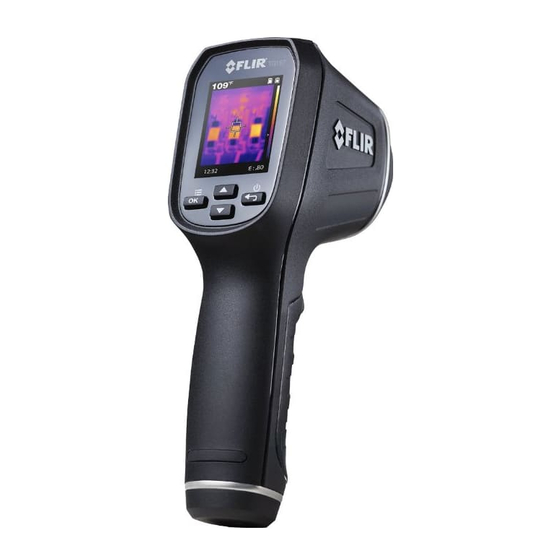
The FLIR TG167 lets you see heat patterns, reliably measure temperature, and store im- ages and data. Its menu uses intuitive icons, making it simple to operate. The FLIR TG167 also makes documentation easy by saving images you can download from the Micro SD card or over a USB connection and use for reports. -
Page 19: Quick Start Guide
• Charge the battery using a USB cable connected to a computer. Note Charging the camera using a USB cable connected to a computer takes considerably longer than using the FLIR power supply or the FLIR stand-alone bat- tery charger. -
Page 20: Description
Description 7.1 View from the front 7.1.1 Figure 7.1.2 Explanation 1. Infrared imaging lens (captures the infrared image). 2. Dual laser pointers. 3. Infrared thermometer lens (captures the infrared thermometer reading). 4. Trigger. 5. Lanyard access. 7.2 View from the rear 7.2.1 Figure 7.2.2 Explanation 1. -
Page 21: View From The Top
Description 4. UP-DOWN buttons Function: • Push to navigate the Settings menu and select settings. • Push and hold the button for 4 seconds to open the image archive. • Push to scroll through saved images in the image archive. 7.3 View from the top 7.3.1 Figure 7.3.2 Explanation... -
Page 22: Ir Imager Field Of View - View From The Side
Description 1. Left and right (horizontal) boundaries of the infrared image field of view (19.3°). 2. Infrared thermometer field of view. 3. Infrared thermometer measurement spot. 4. Infrared image field. 7.6 IR imager field of view — view from the side 1. -
Page 23: Laser Rules And Regulations
Description 7.7.3 Laser rules and regulations Wavelength: 630–670 nm. Maximum output power: 1 mW. This product complies with FDA 1040.10 and 1040.11, IEC 60825–1 (2001–08). Edition 1.2, EN 60825–1:1994/A11:1996/A2:2001/A1:2002 7.8 Screen elements 7.8.1 Figure 7.8.2 Explanation 1. Infrared thermometer reading. 2. -
Page 24: Operation
• To charge the camera, the computer must be turned on. • Charging the camera using a USB cable connected to a computer takes consider- ably longer than using the FLIR power supply or the FLIR stand-alone battery charger. 8.2 Turning on and turning off the camera Follow this procedure: 1. -
Page 25: Saving An Image
Operation 3. Move the camera until only the object of interest is between the laser pointer spots. 4. The measured temperature is displayed on the camera screen. Note If the temperature exceeds the measurement temperature range of the camera, OL is displayed on the screen. 8.4 Saving an image 8.4.1 General To save images, a compatible Micro SD card must be inserted in the Micro SD card slot at... -
Page 26: Viewing A Saved Image
Operation 8.5 Viewing a saved image 8.5.1 General When you save an image, the image file is stored on the memory card. To display the im- age again, open it from the image archive. 8.5.2 Procedure Follow this procedure: 1. To open the image archive, do one of the following: •... -
Page 27: Palette
Operation 8.7.2 Palette 8.7.2.1 General You can change the palette that the camera uses to display different temperatures. Available options for the palette setting: • Hot Iron • Rainbow • Grayscale 8.7.2.2 Procedure Follow this procedure: 1. Push the button to display the Settings menu. 2. -
Page 28: Laser Pointer
Operation • 0.95 • 0.80 • 0.60 • 0.30 • custom (0.01–0.99) Note If you are unsure about the emissivity value, it is recommended to set it to 0.95. 8.7.3.2 Procedure Follow this procedure: 1. Push the button to display the Settings menu. 2. -
Page 29: Crosshair
Operation • °F (Fahrenheit) 8.7.5.2 Procedure Follow this procedure: 1. Push the button to display the Settings menu. 2. Use the buttons to go to the icon. 3. Push the button to toggle through the options. 4. Push the button to exit the Settings menu. 8.7.6 Crosshair 8.7.6.1 General The crosshair indicates the center of the infrared thermometer measurement spot. -
Page 30: Date And Time
For firmware updates, contact FLIR customer support. The camera is calibrated at the factory prior to shipment. The camera is not serviceable in the field, and should be calibrated only by qualified FLIR Systems personnel. If calibration is required, contact FLIR customer support. - Page 31 Operation 8.7.9.2 Procedure Follow this procedure: 1. Push the button to display the Settings menu. 2. Use the buttons to go to the icon. 3. Push the button. This displays information about the firmware version and the cali- bration date. 4.
-
Page 32: Technical Data
Technical data 9.1 Note about technical data FLIR Systems reserves the right to change specifications at any time without prior notice. Please check http://support.flir.com for latest changes. 9.2 Note about authoritative versions The authoritative version of this publication is English. In the event of divergences due to translation errors, the English text has precedence. -
Page 33: Flir Tg167 (Global)
FLIR’s legendary thermal cameras. Equipped with FLIR’s exclusive Lepton micro thermal cam- era, the FLIR TG167 shows you where potential problems are brewing and where to aim your spot. The FLIR TG167 lets you see heat patterns, reliably measure temperature, and store images and data. Its menu uses intuitive icons, making it simple to operate. - Page 34 Technical data Set-up Set-up commands • Local adaptation of units, language, date, and time formats • Deletion of images Emissivity correction 4 pre-set levels with custom adjustment of 0.1– 0.99 Storage of images Memory type Micro SD card Image storage capacity 75 000 pictures with included 8 GB Micro SD card Memory expansion 32 GB SD card maximum...
- Page 35 Technical data Physical data Camera weight, incl. battery 0.312 kg (11 oz.) Camera size (L × W × H) 186 mm × 55 mm × 94 mm (7.3 in. × 2.2 in. × 3.7 in.) Tripod mounting 1/4 in.-20 on handle bottom Color Black, white, silver Material...
-
Page 36: Mechanical Drawings
Mechanical drawings #T559974; r.33562/33594; en-US... -
Page 38: Cleaning The Camera
Cleaning the camera 11.1 Camera housing, cables, and other items 11.1.1 Liquids Use one of these liquids: • Warm water • A weak detergent solution 11.1.2 Equipment A soft cloth 11.1.3 Procedure Follow this procedure: 1. Soak the cloth in the liquid. 2. -
Page 39: Application Examples
Application examples 12.1 Moisture & water damage 12.1.1 General It is often possible to detect moisture and water damage in a house by using an infrared camera. This is partly because the damaged area has a different heat conduction property and partly because it has a different thermal capacity to store heat than the surrounding material. -
Page 40: Figure
Application examples 12.2.2 Figure The image below shows a connection of a cable to a socket where improper contact in the connection has resulted in local temperature increase. 12.3 Oxidized socket 12.3.1 General Depending on the type of socket and the environment in which the socket is installed, ox- ides may occur on the socket's contact surfaces. -
Page 41: Insulation Deficiencies
Application examples 12.4 Insulation deficiencies 12.4.1 General Insulation deficiencies may result from insulation losing volume over the course of time and thereby not entirely filling the cavity in a frame wall. An infrared camera allows you to see these insulation deficiencies because they either have a different heat conduction property than sections with correctly installed insulation, and/or show the area where air is penetrating the frame of the building. -
Page 42: Draft
Application examples 12.5 Draft 12.5.1 General Draft can be found under baseboards, around door and window casings, and above ceil- ing trim. This type of draft is often possible to see with an infrared camera, as a cooler air- stream cools down the surrounding surface. When you are investigating draft in a house, there should be sub-atmospheric pressure in the house. - Page 43 Application examples #T559974; r.33562/33594; en-US...
-
Page 44: About Flir Systems
• DVTEL (2015) Figure 13.1 Patent documents from the early 1960s FLIR Systems has three manufacturing plants in the United States (Portland, OR, Boston, MA, Santa Barbara, CA) and one in Sweden (Stockholm). Since 2007 there is also a man- ufacturing plant in Tallinn, Estonia. -
Page 45: More Than Just An Infrared Camera
13.1 More than just an infrared camera At FLIR Systems we recognize that our job is to go beyond just producing the best infrared camera systems. We are committed to enabling all users of our infrared camera systems to work more productively by providing them with the most powerful camera–software... -
Page 46: Supporting Our Customers
13.3 Supporting our customers FLIR Systems operates a worldwide service network to keep your camera running at all times. If you discover a problem with your camera, local service centers have all the equip- ment and expertise to solve it within the shortest possible time. -
Page 47: Glossary
Glossary The amount of radiation absorbed by an object relative to the re- absorption (ab- sorption factor) ceived radiation. A number between 0 and 1. atmosphere The gases between the object being measured and the camera, nor- mally air. autoadjust A function making a camera perform an internal image correction. - Page 48 Glossary IFOV Instantaneous field of view: A measure of the geometrical resolution of an IR camera. image correc- A way of compensating for sensitivity differences in various parts of tion (internal or live images and also of stabilizing the camera. external) infrared Non-visible radiation, having a wavelength from about 2–13 μm.
- Page 49 Glossary relative Relative humidity represents the ratio between the current water va- humidity pour mass in the air and the maximum it may contain in saturation conditions. saturation The areas that contain temperatures outside the present level/span color settings are colored with the saturation colors. The saturation colors contain an ‘overflow’...
-
Page 50: History Of Infrared Technology
History of infrared technology Before the year 1800, the existence of the infrared portion of the electromagnetic spectrum wasn't even suspected. The original significance of the infrared spectrum, or simply ‘the in- frared’ as it is often called, as a form of heat radiation is perhaps less obvious today than it was at the time of its discovery by Herschel in 1800. - Page 51 History of infrared technology Moving the thermometer into the dark region beyond the red end of the spectrum, Her- schel confirmed that the heating continued to increase. The maximum point, when he found it, lay well beyond the red end – in what is known today as the ‘infrared wavelengths’. When Herschel revealed his discovery, he referred to this new portion of the electromag- netic spectrum as the ‘thermometrical spectrum’.
- Page 52 History of infrared technology Figure 15.4 Samuel P. Langley (1834–1906) The improvement of infrared-detector sensitivity progressed slowly. Another major break- through, made by Langley in 1880, was the invention of the bolometer. This consisted of a thin blackened strip of platinum connected in one arm of a Wheatstone bridge circuit upon which the infrared radiation was focused and to which a sensitive galvanometer re- sponded.
-
Page 53: Emissivity Tables
Emissivity tables This section presents a compilation of emissivity data from the infrared literature and measurements made by FLIR Systems. 16.1 References 1. Mikaél A. Bramson: Infrared Radiation, A Handbook for Applications, Plenum press, N. 2. William L. Wolfe, George J. Zissis: The Infrared Handbook, Office of Naval Research, Department of Navy, Washington, D.C. - Page 54 Emissivity tables Table 16.1 T: Total spectrum; SW: 2–5 µm; LW: 8–14 µm, LLW: 6.5–20 µm; 1: Material; 2: Specification; 3: Temperature in °C; 4: Spectrum; 5: Emissivity: 6:Reference (continued) Aluminum anodized, black, 0.95 dull Aluminum anodized, light 0.61 gray, dull Aluminum anodized, light 0.97...
- Page 55 Emissivity tables Table 16.1 T: Total spectrum; SW: 2–5 µm; LW: 8–14 µm, LLW: 6.5–20 µm; 1: Material; 2: Specification; 3: Temperature in °C; 4: Spectrum; 5: Emissivity: 6:Reference (continued) Asphalt paving 0.967 Brass dull, tarnished 20–350 0.22 Brass oxidized 0.61 Brass oxidized...
- Page 56 Emissivity tables Table 16.1 T: Total spectrum; SW: 2–5 µm; LW: 8–14 µm, LLW: 6.5–20 µm; 1: Material; 2: Specification; 3: Temperature in °C; 4: Spectrum; 5: Emissivity: 6:Reference (continued) Bronze phosphor bronze 0.06 Bronze polished Bronze porous, rough 50–150 0.55 Bronze powder...
- Page 57 Emissivity tables Table 16.1 T: Total spectrum; SW: 2–5 µm; LW: 8–14 µm, LLW: 6.5–20 µm; 1: Material; 2: Specification; 3: Temperature in °C; 4: Spectrum; 5: Emissivity: 6:Reference (continued) Ebonite 0.89 coarse 0.85 Emery Enamel Enamel lacquer 0.85–0.95 Fiber board hard, untreated 0.85 Fiber board...
- Page 58 Emissivity tables Table 16.1 T: Total spectrum; SW: 2–5 µm; LW: 8–14 µm, LLW: 6.5–20 µm; 1: Material; 2: Specification; 3: Temperature in °C; 4: Spectrum; 5: Emissivity: 6:Reference (continued) Iron and steel oxidized 125–525 0.78–0.82 Iron and steel oxidized 0.79 Iron and steel oxidized...
- Page 59 Emissivity tables Table 16.1 T: Total spectrum; SW: 2–5 µm; LW: 8–14 µm, LLW: 6.5–20 µm; 1: Material; 2: Specification; 3: Temperature in °C; 4: Spectrum; 5: Emissivity: 6:Reference (continued) Krylon Ultra-flat Flat black Room tempera- ≈ 0.96 black 1602 ture up to 175 Krylon Ultra-flat Flat black...
- Page 60 Emissivity tables Table 16.1 T: Total spectrum; SW: 2–5 µm; LW: 8–14 µm, LLW: 6.5–20 µm; 1: Material; 2: Specification; 3: Temperature in °C; 4: Spectrum; 5: Emissivity: 6:Reference (continued) Nichrome sandblasted 0.70 Nichrome wire, clean 0.65 Nichrome wire, clean 500–1000 0.71–0.79 Nichrome...
- Page 61 Emissivity tables Table 16.1 T: Total spectrum; SW: 2–5 µm; LW: 8–14 µm, LLW: 6.5–20 µm; 1: Material; 2: Specification; 3: Temperature in °C; 4: Spectrum; 5: Emissivity: 6:Reference (continued) Paint cobalt blue 0.7–0.8 0.87 Paint Paint oil based, average 0.94 of 16 colors Paint...
- Page 62 Emissivity tables Table 16.1 T: Total spectrum; SW: 2–5 µm; LW: 8–14 µm, LLW: 6.5–20 µm; 1: Material; 2: Specification; 3: Temperature in °C; 4: Spectrum; 5: Emissivity: 6:Reference (continued) Plastic 0.94 PVC, plastic floor, dull, structured Plastic PVC, plastic floor, 0.93 dull, structured Platinum...
- Page 63 Emissivity tables Table 16.1 T: Total spectrum; SW: 2–5 µm; LW: 8–14 µm, LLW: 6.5–20 µm; 1: Material; 2: Specification; 3: Temperature in °C; 4: Spectrum; 5: Emissivity: 6:Reference (continued) sheet, untreated, 0.30 Stainless steel somewhat scratched Stainless steel sheet, untreated, 0.28 somewhat scratched...
- Page 64 Emissivity tables Table 16.1 T: Total spectrum; SW: 2–5 µm; LW: 8–14 µm, LLW: 6.5–20 µm; 1: Material; 2: Specification; 3: Temperature in °C; 4: Spectrum; 5: Emissivity: 6:Reference (continued) Water snow –10 0.85 0.98 Wood Wood 0.962 Wood ground 0.5–0.7 Wood pine, 4 different...
- Page 66 A note on the technical production of this publication This publication was produced using XML — the eXtensible Markup Language. For more information about XML, please visit http://www.w3.org/XML/ A note on the typeface used in this publication This publication was typeset using Linotype Helvetica™ World. Helvetica™ was designed by Max Miedinger (1910–1980) LOEF (List Of Effective Files) T501136.xml;...
- Page 68 Disclaimer Specifications subject to change without further notice. Models and accessories subject to regional market considerations. License procedures may apply. Products described herein may be subject to US Export Regulations. Please refer to exportquestions@flir.com with any questions. Publ. No.: T559974...
Need help?
Do you have a question about the FLIR TG167 and is the answer not in the manual?
Questions and answers