Table of Contents
Advertisement
Advertisement
Table of Contents

Related Manuals for FLIR TG275


Summary of Contents for FLIR TG275
- Page 1 USER MANUAL Automotive Diagnostic Thermal Camera Model TG275...
- Page 3 USER MANUAL Automotive Diagnostic Thermal Camera #NAS100009; r. AA/57810/57810; en-US...
-
Page 5: Table Of Contents
Programming Menu System ..........10 Menu System Basics ..........10 Main Menu .............. 10 SETTINGS Sub-Menu ..........12 Bluetooth® Communication and FLIR Tools™ ...... 17 FCC Compliance ............17 Field Firmware Upgrades ........... 19 System Firmware upgrade .......... 19 Bluetooth® Firmware upgrade........19 Maintenance .............. - Page 6 Table of contents 10.3 Image Presentation Specifications........ 21 10.4 Measurement Specifications ........22 10.5 Measurement Analysis Specifications ......22 10.6 Configuration Specifications........22 10.7 Image Storage Specifications ........23 10.8 Digital Camera ............23 10.9 Flashlight Specifications..........23 10.10 Laser Pointer Specifications ........23 10.11 Data Communication and Interface Specifications ...
-
Page 7: Advisories
Advisories 1.1 Copyright ©2019, FLIR Systems, Inc. All rights reserved worldwide. No parts of the software including source code may be reproduced, transmitted, transcribed or translated into any language or computer language in any form or by any means, electronic, magnetic, optical, manual or otherwise, without the prior written permission of FLIR Systems. -
Page 8: Introduction
Register the TG275 within 60 days to activate the 2–10 Year Warranty Extension at this link: https://support.flir.com/prodreg. Features •... -
Page 9: Safety
Safety 3.1 Safety Warnings and Cautions WARNING ⚠ This symbol, adjacent to another symbol indicates the user must refer to the manual for further information. WARNING The instrument’s IP54 rating is only in affect when the top flap (covering the USB-C jack) is completely sealed. -
Page 10: Description
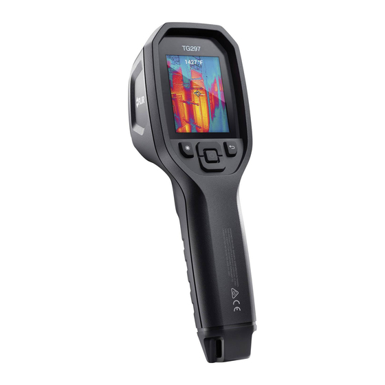
Description 4.1 Product Description Figure 4.1 Imaging IR Thermometer Description 1. Display area 2. Return button (to back up in the menu system) 3. Laser pointer button 4. Up/Down Navigation buttons & Power (long press)/Menu (short press) button 5. Lanyard post 6. -
Page 11: Control Button Descriptions
Press to activate the Laser pointer Pull trigger to capture camera image TRIGGER Pull trigger to exit the menu system 4.3 Display Description Figure 4.2 TG275 Displays 1. Menu area 2. Date and time 3. Battery status indicators 4. Bluetooth® active 5. - Page 12 Description 7. Camera image area 8. Center spot cross-hairs 9. Laser Pointer active 10. Center spot temperature measurement #NAS100009; r. AA/57810/57810; en-US...
-
Page 13: Operation
(not supplied) using the supplied USB-C cable. The USB-C jack is located in the compartment at the top of the TG275. Do not use the TG275 while it is charging. When the top flap is closed, the TG275 is rated IP54 for encapsula- tion. -
Page 14: High Temperature Switch
(under Measurement) to see if the Center Spot (cross-hairs) function is enabled. 5. Press the Laser pointer button to switch ON the Laser pointer. The TG275 Laser pointer includes a circular spot indicating the area that is being monitored for temperature. -
Page 15: Visible Spectrum Camera
TG275 to a PC using the supplied USB-C cable. The USB jack is located at the top of the TG275 under the flap. Once connected to the PC you can use the TG275 as you would any external storage drive. -
Page 16: Programming Menu System
Programming Menu System 6.1 Menu System Basics Short press the MENU button to access the menu system. Use the MENU button to switch settings ON or OFF, use the Return button to move to the pre- vious screen, and use the arrows to scroll. In addition, the MENU button is used in some cases to confirm settings. - Page 17 Programming Menu System 1. Image Modes: Press MENU at IMAGE MODES and use the arrow buttons to select VISIBLE IMAGE or THERMAL PLUS VISIBLE IMAGE (MSX®). 2. MSX® Alignment: While at the Image Mode menu you can adjust the MSX® alignment so that the thermal image and the visible image are aligned accurately.
-
Page 18: Settings Sub-Menu
Programming Menu System 3. Colors: Press MENU at the Colors menu and use the arrow buttons to se- lect a color palette: Iron, Rainbow, White hot, Black hot, Arctic, or Lava. Press MENU to confirm selection. • SETTINGS: Press MENU to access the Settings sub-menu (see below): 6.3 SETTINGS Sub-Menu •... - Page 19 Programming Menu System 1. Center Spot: Press MENU to enable/disable the display cross-hairs. The cross-hairs identify the spot that is being measured for temperature. 2. Emissivity: Press MENU to open the Emissivity adjustment utility. Use the arrows to scroll through the presets (0.95, 0.80, and 0.60) and use the MENU button to select a preset.
- Page 20 Programming Menu System 2. Laser: Press MENU to enable/disable the Laser pointer. When enabled, you can use the Laser pointer button to switch ON the Laser pointer. 3. Screen brightness: Use the arrows to select the desired display intensity (LOW, MEDIUM, or HIGH). 4.
- Page 21 Programming Menu System 1. Temperature Unit: Use the arrows and the MENU button to select °C or °F. 2. Time & Date: Use the arrows to scroll and the MENU button to set the Time, Date, Time Format, and Date Format. 3.
- Page 22 Programming Menu System 4. System Info: Scroll to desired topic: Model Number, Serial Number, Software Level, Revision, Battery status (%), and remaining Internal Storage Capacity. • GENERAL SYSTEM INFO: Press MENU to view company information. #NAS100009; r. AA/57810/57810; en-US...
-
Page 23: Bluetooth® Communication And Flir Tools
App and search for the TG275 (the TG275 must be ON). Tap in the App to connect to the TG275. When connected to a device running the App, the TG275 (using the METERLiNK® protocol) contin- ually sends readings for live display on the remote device. - Page 24 Bluetooth® Communication and FLIR Tools™ WARNING Changes or modifications not expressly approved by the party responsible for compliance could void the user’s authority to operate the equipment. #NAS100009; r. AA/57810/57810; en-US...
-
Page 25: Field Firmware Upgrades
System firmware or the Bluetooth® firmware by first downloading an upgrade file from the FLIR website and then connecting the TG275 to a PC (using the supplied USB-C cable) to transfer the file to the TG275. Firmware upgrades are available from https://support.flir.com. -
Page 26: Maintenance
90% power requires 4 hours. Charging through a PC USB port is not recommended. If the TG275 is not going to be used for an extended period (> 3 months), it should be charged to 70% then stored at room temperature and recharged every 6 months. -
Page 27: Specifications
Specifications 10.1 Imaging and Optical Specifications IR resolution 160 x 120 pixels Digital image enhancement Included Thermal Sensitivity /NETD < 70 mK Field of View (FOV) 57° x 44° Minimum focus distance 0.3 m (0.89 ft.) 30:1 Distance-to-Spot ratio Dual range operation Range 1: <... -
Page 28: Measurement Specifications
Specifications 10.4 Measurement Specifications Object temperature range -25 ~ 550℃ (-13 ~ 1022℉) Accuracy at ambient temperature: 15 ~ -25℃ to 0℃ (-13℉ ~ 32℉): ± 3.0℃ (7.0℉) 35℃ (59 ~95℉) 0℃ ~ 50℃ (32℉ ~ 122℉): ±2.5℃ or ± 2.5% (±... -
Page 29: Image Storage Specifications
Specifications Languages Czech, Danish, Dutch, English, Finnish, French, German, Greek, Hungarian, Italian, Japanese, Korean, Norwegian, Polish, Por- tuguese, Russian, simplified Chinese, Spanish, Swedish, traditional Chinese, Turkish Firmware upgrades User manageable (instructions included in this user manual) 10.7 Image Storage Specifications Storage media eMMC 4G Image storage capacity... -
Page 30: Data Communication And Interface Specifications
4.5 hours with Laser ON (medium bright- ness setting) Battery charge life 30 days minimum Charging system Battery is charged inside the TG275 Charging time 4 hours to 90% and 6 hours to 100% Power management APO adjustable 5/15/30 minutes. Can be disabled. -
Page 31: Physical Specifications
Size (L x W x H) 210 x 64 x 81 mm (8.3 x 2.5 x 3.2 in.) Accessory mount UNC ¼”-20 10.15 Included Equipment Standard equipment TG275, USB-C cable, printed, Quick Start Guide, Lan- yard, Carry Pouch #NAS100009; r. AA/57810/57810; en-US... -
Page 32: Appendices
It may take some time to get used to the thermal im- agery. Having a basic understanding of the differences between thermal and daylight cameras can help with getting the best performance from the TG275. One difference between thermal and daylight cameras has to do with where the energy comes from to create an image. - Page 33 Appendices puddles of water and other cold objects appear dark (or cool). Scenes with fa- miliar objects will be easy to interpret with some experience. Infrared energy is part of a complete range of radiation called the electromag- netic spectrum. The electromagnetic spectrum includes gamma rays, X-rays, ultraviolet, visible, infrared, microwaves (RADAR), and radio waves.
-
Page 34: 12 2-10 Extended Warranty
Otherwise, the standard one-year warranty will be in affect from date of purchase. The 2–10 warranty covers parts and labor for the cam- era for 2 years and coverage of the detector for 10 years. Register your prod- uct at https://support.flir.com/prodreg. #NAS100009; r. AA/57810/57810; en-US... -
Page 35: Customer Support
Customer Support Repair, Calibration, and Technical Support: https://support.flir.com. #NAS100009; r. AA/57810/57810; en-US... - Page 36 #NAS100009; r. AA/57810/57810; en-US...
- Page 38 Customer support http://support.flir.com Copyright © 2019, FLIR Systems, Inc. All rights reserved worldwide. Disclaimer Specifications subject to change without further notice. Models and accessories subject to regional market considerations. License procedures may apply. Products described herein may be subject to US Export Regulations.
Need help?
Do you have a question about the TG275 and is the answer not in the manual?
Questions and answers