Table of Contents
Advertisement
Quick Links
User Manual of Product 1:
FLIR - E5-XT with WiFi & MSX E5-XT - Handheld Infrared
Camera - with Extended Temperature Range, MSX Image
Enhancement Technology, Wi-Fi & Bluetooth for Instant Data
Sharing - (160 x 120)
User Manual of Product 2:
Klein Tools ET120 Gas Leak Detector, Combustible Gas Leak
Tester with 18-Inch Gooseneck Has Range 50 - 10,000 ppm,
Includes Pouch, Batteries
Advertisement
Table of Contents

Subscribe to Our Youtube Channel
Related Manuals for FLIR E5-XT


Summary of Contents for FLIR E5-XT
- Page 1 User Manual of Product 1: FLIR - E5-XT with WiFi & MSX E5-XT - Handheld Infrared Camera - with Extended Temperature Range, MSX Image Enhancement Technology, Wi-Fi & Bluetooth for Instant Data Sharing - (160 x 120) User Manual of Product 2:...
- Page 2 USER MANUAL Diagnostic Thermal Camera Models TG267, TG297, and TG165–X...
- Page 4 USER MANUAL Diagnostic Thermal Camera #NAS100014; r. AK/74592/74592; en-US...
-
Page 6: Table Of Contents
Bluetooth® Communication and FLIR Tools™ ...... 22 Bluetooth® Communication Overview......22 Download the FLIR Tools™ Mobile App......22 Setting up the FLIR Tools™ Mobile App......22 Transmit Images via Bluetooth® ........22 FCC Compliance ............24 GITEKI Certified ............25 Field Firmware Updates ............. - Page 7 Table of contents Reset the Camera............. 27 Specifications..............28 10.1 Imaging and Optical Specifications ....... 28 10.2 Detector Specifications ..........28 10.3 Image Presentation Specifications........ 28 10.4 Measurement Specifications ........29 10.5 Measurement Analysis Specifications ......29 10.6 Type-K specifications (TG267 only) ......29 10.7 Configuration Specifications........
-
Page 8: Advisories
The documentation must not, in whole or part, be copied, photocopied, repro- duced, translated or transmitted to any electronic medium or machine-read- able form without prior consent, in writing, from FLIR Systems. Names and marks appearing on the products herein are either registered trademarks or trademarks of FLIR Systems and/or its subsidiaries. -
Page 9: Introduction
The FLIR TG267 adds Type-K thermocouple contact temperature measurements. The FLIR TG297 offers a high temperature range to 1886℉ (1030℃). Visit https://support.flir.com/prodreg to register your instrument and to extend the standard one-year warranty to the 2-10 Year Warranty. -
Page 10: Safety
Safety 3.1 Safety Warnings and Cautions WARNING ⚠This symbol, adjacent to another symbol indicates the user must refer to the manual for further information. WARNING The instrument’s IP54 rating is only in affect when the top flap (covering the USB-C and Thermocouple jacks) is completely sealed. -
Page 11: Description
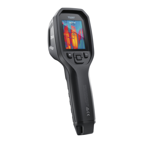
Description 4.1 Product Description Figure 4.1 Imaging IR Thermometer Description (TG297 pictured) 1. Display area 2. Return button (to back up in the menu system) 3. Laser pointer button 4. Up/Down Navigation buttons and Power button (long press)/Menu button (short press) 5. -
Page 12: Control Button Descriptions
Description 4.2 Control Button Descriptions Long press to power ON or OFF Short press to access the menu system Return button. Back out to previous screen in menus Press to scroll upward in the menus Press to scroll downward in the menus Press to activate the Laser pointer Pull trigger to capture camera image TRIGGER... - Page 13 Description 7. Camera image area 8. Center spot cross-hairs 9. Laser Pointer active 10. Center spot temperature measurement 11. Thermocouple measurement (TG267) #NAS100014; r. AK/74592/74592; en-US...
-
Page 14: Operation
Operation 5.1 Camera Power Power is supplied by a rechargeable lithium battery. Long press the power button (center) to switch the camera ON or OFF. If the camera does not power ON, charge the battery by connecting to an AC wall charger using the sup- plied USB-C cable. -
Page 15: High Temperature Switch (Tg297)
Operation 4. Use the Laser pointer to accurately target a spot. Press the Laser pointer button to switch ON the Laser pointer. The camera’s Laser pointer in- cludes a circular spot indicating the area that is being monitored for tem- perature, utilizing DOE (Diffractive Optical Elements) technology. -
Page 16: Type-K Thermocouple Measurements (Tg267)
TG267. If the thermocouple does not include a range label, please contact FLIR technical support. WARNING To avoid electrical shock, do not use this instrument when working near voltages > 24V AC/DC. - Page 17 Operation Figure 5.4 Thermocouple temperature readout (33.7℃, in this example) 1. If necessary, enable the thermocouple mode in the menu system (under Measurement). The thermocouple is enabled when the ‘TC’ label is shown on the display. 2. Connect a Type-K thermocouple sub-miniature plug (see Figure 5.3) to the jack in the top compartment.
-
Page 18: Visible Spectrum Camera
Operation 5.5 Visible Spectrum Camera Figure 5.5 Visible Spectrum Digital Camera Image 1. Long press the power button to switch the camera ON. 2. Select a Visible Image mode in the menu system (under Image Adjust- ments/Image Mode). Note that the high resolution Visible Image mode does not support object temperature measurements. - Page 19 Operation 6. To transmit images via Bluetooth®, see Section 7, Bluetooth® Communi- cation and FLIR Tools™. Note that the TG165–X does not include Blue- tooth® capability. #NAS100014; r. AK/74592/74592; en-US...
-
Page 20: Programming Menu System
DELETE/DELETE ALL FILES menu. Select SEND to transmit the selected image to a paired mobile device (see Section 7, Bluetooth® Communica- tion and FLIR Tools™, for more information. Note that the TG165–X does not include Bluetooth® capability). • IMAGE ADJUSTMENTS: Press MENU to access IMAGE MODES (includ- ing MSX®... - Page 21 Programming Menu System 1. Image Modes: Press MENU at IMAGE MODES to open the Image Mode menu. Use the arrow buttons to select an image mode: THERMAL PLUS VISI- BLE (MSX®), VISIBLE (QVGA 320 x 120 pixels), or HIGH RESOLUTION VISIBLE mode (2M: 1600 x 1200 pixels).
- Page 22 Programming Menu System 2. MSX® Alignment: Adjust the alignment (so that the thermal image and the visible image line up accurately) as follows: While viewing the THERMAL PLUS VISIBLE IMAGE screen in the menu, press MENU to access the MSX® adjustment screen and then use the arrow buttons to adjust the alignment.
-
Page 23: Settings Sub-Menu
Programming Menu System 3. Colors: Press MENU at the colors menu and use the arrow buttons to se- lect a color palette: Iron, Rainbow, White hot, Black hot, Arctic, or Lava. Press MENU to confirm selection. • SETTINGS: Press MENU to access the Settings sub-menu (see below): 6.3 Settings Sub-Menu •... - Page 24 Programming Menu System 1. Center Spot: Press MENU to enable/disable the display cross-hairs. The cross-hairs should be used as a reference only to identify the spot that is being measured for temperature. Use the Laser pointer for more accurate targeting. Note that the high resolution Visible Spectrum Image Mode does not sup- port object temperature measurements and so the centre spot cannot be switched ON/OFF while in the high resolution Image Mode.
- Page 25 (TG267 only). • DEVICE SETTINGS 1. Bluetooth® (TG267 and TG297 only): Press MENU to switch Bluetooth® ON or OFF. See Section 7, Bluetooth® Communication and FLIR Tools™, for details. 2. Laser: Press MENU to enable/disable the Laser pointer. When enabled, you can use the Laser pointer button to switch ON the Laser pointer.
- Page 26 Programming Menu System 3. Screen brightness: Use the arrows to select the desired display intensity (LOW, MEDIUM, or HIGH). 4. Auto Power OFF (APO): Use the arrows to scroll and MENU to select the desired APO time (5/15/30 minutes). Set to ‘Never’ to disable APO. •...
- Page 27 Programming Menu System 2. Time & Date: Use the arrows to scroll and the MENU button to set the Time, Date, Time Format, and Date Format. 3. Language: Use the arrows to scroll and the MENU button to select a language.
- Page 28 Programming Menu System • FACTORY RESET: Follow the prompts to reset the User Settings back to Factory Default status. #NAS100014; r. AK/74592/74592; en-US...
-
Page 29: Bluetooth® Communication And Flir Tools
FLIR Tools™ 7.1 Bluetooth® Communication Overview When paired with a mobile device running the FLIR Tools™ App (using the METERLiNK® protocol), the TG267 and TG297 continually transmit readings for live display on the mobile device. You can also send images, stored on the camera, to your mobile device. - Page 30 Bluetooth® Communication and FLIR Tools™ Figure 7.1 Pairing the camera with a Mobile Device Figure 7.2 Sending Images to a Mobile Device #NAS100014; r. AK/74592/74592; en-US...
-
Page 31: Fcc Compliance
Bluetooth® Communication and FLIR Tools™ Figure 7.3 Viewing Transferred Images on a Mobile Device 7.5 FCC Compliance This device complies with part 15 of the FCC Rules. Operation is subject to the following two conditions: 1. This device may not cause harmful interference. -
Page 32: Giteki Certified
Bluetooth® Communication and FLIR Tools™ 4. Consult the dealer or an experienced radio/TV technician for help. WARNING Changes or modifications not expressly approved by the party responsible for compliance could void the user’s authority to operate the equipment. 7.6 GITEKI Certified This product is GITEKI certified. -
Page 33: Field Firmware Updates
System firmware by first downloading an update file from the FLIR website and then transferring the file to the camera via USB. Connect to a PC using a USB-C cable. Firmware updates are available from https://support.flir.com. -
Page 34: Maintenance
Clean the lenses with a high-quality lens cleaner. 9.2 Battery Considerations and Service The rechargeable lithium battery is not user-serviceable. Please contact FLIR support for service instructions: https://support.flir.com. For best results, charge the battery immediately after seeing a low battery in- dication using the supplied USB-C cable (with an AC wall charger, not sup- plied). -
Page 35: Specifications
Specifications 10.1 Imaging and Optical Specifications IR resolution TG267 and TG297: 160 x 120 pixels TG165–X: 80 x 60 pixels Digital image enhancement Included Thermal Sensitivity /NETD < 70 mK Field of View (FOV) TG267 and TG297: 57° (H) x 44° (D) TG165–X: 51°... -
Page 36: Measurement Specifications
Specifications Image adjustment Automatic Image modes • Thermal MSX® (Multi-Spectral Dynam- ic Imaging) • Visible Spectrum (standard and high resolution modes) 10.4 Measurement Specifications Object temperature range TG267: –13 ~ +716℉ (–25 ~ +380℃) TG297: –13 ~ +1886℉ (–25 ~ +1030℃) TG165–X: –13 ~ +572℉... -
Page 37: Configuration Specifications
Please do not exceed the specified range printed on the thermocouple label. To measure higher or lower than the range of the supplied thermocouple, please use a Type-K thermocouple rated for the desired range. Contact FLIR for additional information 10.7 Configuration Specifications... -
Page 38: Flashlight Specifications
Specifications 10.10 Flashlight Specifications Flashlight type Bright LED 6500° K LED CCT LED CRI Beam angle ± 20° Rated power 0.5 W Light output 100 Lumens 10.11 Laser Pointer Specifications Laser type DOE (Diffractive optical elements) Laser function Indicates the size of the measurement area (circular target) Laser class Class I... -
Page 39: Environmental Specifications
Specifications Charging time 4 hours to 90% and 6 hours to 100% Power management APO adjustable 5/15/30 minutes. Can be disabled. 10.14 Environmental Specifications Altitude 6562 ft. (2000 m) Pollution degree Operating temperature 14 ~ 113℉ (-10 ~ 45℃) Storage temperature -22 ~ 131℉... -
Page 40: Physical Specifications
Specifications Environmental safety REACH Regulation EC 1907/2006 RoHS 2 Directive 2011/65/EC WEEE Directive 2012/19/EC JIS C 6802:2011 laser directive IEC 60825–1 class I laser directive FDA laser directive Humidity requirements IEC 60068–2–30 for operation and storage 10.15 Physical Specifications Weight 13.9 oz. -
Page 41: 11 2-10 Extended Warranty
Otherwise, the standard one-year warranty will be in affect from date of purchase. The 2–10 warranty covers parts and labor for the cam- era for 2 years and coverage of the detector for 10 years. Register your prod- uct at https://support.flir.com/prodreg. #NAS100014; r. AK/74592/74592; en-US... -
Page 42: Customer Support
Customer Support Repair, Calibration, and Technical Support: https://support.flir.com. 12.1 Corporate Headquarters FLIR Systems, Inc. 27700 SW Parkway Avenue Wilsonville, OR 97070, USA #NAS100014; r. AK/74592/74592; en-US... - Page 43 #NAS100014; r. AK/74592/74592; en-US...
- Page 45 Customer support http://support.flir.com Copyright © 2021, FLIR Systems, Inc. All rights reserved worldwide. Disclaimer Specifications subject to change without further notice. Models and accessories subject to regional market considerations. License procedures may apply. Products described herein may be subject to US Export Regulations.
- Page 46 ET120 ENGLISH INSTRUCTION MANUAL Combustible Gas Leak Detector • DETECTS A RANGE OF COMBUSTIBLE GASSES • AUDIBLE AND VISUAL ALARMS • DATA HOLD ESPAÑOL pg. 7 FRANÇAIS pg. 13...
- Page 47 ENGLISH GENERAL SPECIFICATIONS Klein Tools ET120 is an easy-to-use tester that provides audible and visual alarms in the presence of methane, propane and butane at concentrations as low as 50 ppm. • Audible Alert: 85 db ticking, modulation proportional to gas concentration •...
- Page 48 FEATURE DETAILS Front of Back of Tester Tester Gooseneck Auto Power-Off Button Gooseneck Clip LOW Sensitivity Mode Button Sensor Head HIGH Sensitivity Mode Button Indicator Lights HOLD Button LOW Alert Light Power Button HIGH Alert Light 1/4-20 UNC Tripod Mount Auto-Zero Button Battery Door Mute Button...
- Page 49 ENGLISH SYMBOLS ON METER Warning Wear approved eye protection Risk of Read instructions Electric Shock Not intended for use as Personal Explosive Materials Protective Equipment (PPE) Do NOT probe moving machinery FUNCTION BUTTONS AUTO-ZERO BUTTON Press to set zero point in a known clean environment. MUTE BUTTON Press to mute the audible alarm.
- Page 50 OPERATING INSTRUCTIONS 1. In an area where combustible gas is known to be not present, press the power button for 3 seconds. The tester will beep and start a 50-second zero-calibration process while the first indicator light blinks . Once complete, all indicator lights will blink for one second, then the HIGH indicator light will illuminate and...
- Page 51 ENGLISH MAINTENANCE BATTERY REPLACEMENT When both the LOW alert light and HIGH alert light are illuminated at the same time, the batteries must be replaced. WARNING: Do NOT replace batteries in an explosive atmosphere. 1. Loosen screw and remove battery door 2.
- Page 52 ET120 ESPAÑOL MANUAL DE INSTRUCCIONES Detector de fuga de gas combustible • DETECTA UNA VARIEDAD DE GASES COMBUSTIBLES • ALARMAS AUDIBLES Y VISUALES • RETENCIÓN DE DATOS...
- Page 53 ESPAÑOL ESPECIFICACIONES GENERALES El ET120 de Klein Tools es un medidor fácil de utilizar que emite alarmas audibles y visuales ante la presencia de metano, propano y butano en concentraciones tan bajas como 50 ppm. • Alarma audible: tictac de 85 dB, con modulación proporcional a la concentración de gas •...
- Page 54 DETALLES DE LAS CARACTERÍSTICAS Parte posterior Parte frontal del probador del probador 1. Cuello de cisne 10. Botón LOW Sensitivity 2. Sujetador del cuello de cisne (Modo de sensibilidad baja) 3. Cabeza del sensor 11. Botón HIGH Sensitivity 4. Luces indicadoras (Modo de sensibilidad alta) 5.
- Page 55 ESPAÑOL SÍMBOLOS DEL MEDIDOR Advertencia Use protección para ojos aprobada. Riesgo de Lea las instrucciones. choque eléctrico. No diseñado para usarlo Material explosivo. como equipo de protección personal (PPE). NO utilizar la sonda en máquinas en movimiento. BOTONES DE FUNCIONES BOTÓN AUTO-ZERO (CALIBRACIÓN AUTOMÁTICA DEL CERO) Presione este botón para establecer el punto cero en un ambiente puro conocido.
- Page 56 INSTRUCCIONES DE OPERACIÓN 1. En áreas donde se sabe que hay presencia de gas combustible, mantenga presionado el botón de encendido durante 3 segundos. El probador emitirá un pitido e iniciará un proceso de calibración del cero que durará 50 segundos, mientras la primera luz indicadora se enciende de forma intermitente.
- Page 57 ESPAÑOL MANTENIMIENTO REEMPLAZO DE LAS BATERÍAS Cuando ambas luces de alarma, LOW (Baja) 5 y HIGH (Alta) 6 , se encienden al mismo tiempo, se deben reemplazar las baterías. ADVERTENCIA: NO reemplace las baterías en una atmósfera explosiva. 1. Afloje el tornillo y retire la tapa del compartimento de baterías 15 .
- Page 58 ET120 FRANÇAIS MANUEL D’UTILISATION Détecteur de fuite de gaz combustible • DÉTECTE PLUSIEURS GAZ COMBUSTIBLES • ALARMES SONORES ET VISUELLES • MAINTIEN DES DONNÉES...
- Page 59 FRANÇAIS CARACTÉRISTIQUES GÉNÉRALES Le détecteur ET120 de Klein Tools est un testeur facile à utiliser qui déclenche des alarmes sonores et visuelles en présence de méthane, de propane et de butane à des concentrations aussi faibles que 50 ppm. • Alerte sonore : son de clic de 85 dB dont la modulation est proportionnelle à la concentration de gaz •...
- Page 60 CARACTÉRISTIQUES DÉTAILLÉES Avant du Arrière du testeur testeur 1. Col de cygne 9. Bouton APO (arrêt automatique) 2. Pince pour le col de cygne 10. Mode de sensibilité LOW (faible) 3. Tête du capteur 11. Mode de sensibilité HIGH (élevée) 4.
- Page 61 FRANÇAIS SYMBOLES SUR LE DÉTECTEUR Porter une protection Avertissement oculaire approuvée Risque de Lire les instructions choc électrique Ne fait pas office d’EPI Matières explosives Ne PAS utiliser sur des pièces en mouvement BOUTONS DE FONCTION BOUTON AUTO ZERO (ÉTALONNAGE AUTOMATIQUE DU ZÉRO) Appuyez sur ce bouton pour configurer le point de référence zéro dans un environnement que vous savez exempt de gaz combustibles.
- Page 62 INSTRUCTIONS D’UTILISATION 1. Dans une zone que vous savez exempte de gaz combustibles, appuyez sur le bouton de mise sous tension et maintenez- le enfoncé pendant 3 secondes. Le testeur émettra un signal sonore et lancera un processus d’étalonnage du zéro sur 50 secondes.
- Page 63 FRANÇAIS ENTRETIEN REMPLACEMENT DES PILES Lorsque les témoins d’alerte LOW (faible) 5 et HIGH (élevée) 6 sont allumés en même temps, cela signifie que les piles doivent être remplacées. AVERTISSEMENT : Ne remplacez PAS les piles du détecteur dans une atmosphère explosive. 1.
- Page 64 NOTES / NOTAS / REMARQUES...
- Page 65 NOTES / NOTAS / REMARQUES KLEIN TOOLS, INC. 450 Bond Street Lincolnshire, IL 60069 1-877-775-5346 customerservice@kleintools.com www.kleintools.com 1390185 Rev 06/17 B...
Need help?
Do you have a question about the E5-XT and is the answer not in the manual?
Questions and answers