Table of Contents

Related Manuals for Dometic PCD5501


Summary of Contents for Dometic PCD5501
- Page 1 Dometic Interact Installation Manual ....2 WARNING Cancer and Reproductive Harm www.P65Warnings.ca.gov REVISION A | Form No. 3317465.000 07/2020 | ©2020 Dometic Corporation...
-
Page 2: Table Of Contents
3.9 Installing the Touch-screen Display ..17 2.3.1 PCD5501 LCD Display ....5 4 Configuration ......17 2.3.2 DB-100 DC Distribution Board . -
Page 3: Explanation Of Symbols And Safety Instructions
Failure to obey the following warnings could result in death or serious injury: DANGER! • Use only Dometic replacement parts and components Indicates a hazardous situation that, if not avoided, that are specifically approved for use with the will result in death or serious injury. -
Page 4: Intended Use
RJ-11 and RJ-12 6-Conductor Cables for the Air Conditioner 2.1 Intended Use (AC) and Fan Dometic Interact is intended to be used in conjunction Connectors with the existing control and/or monitoring devices within your RV. It does not replace the actual hardware 5557 Series Molex Connectors: 12-pin 39-01-2120, 6-pin controllers for the systems within the RV. -
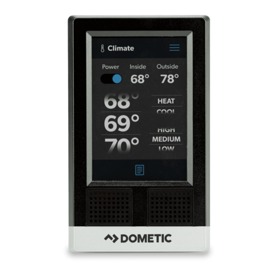
Page 5: Pcd5501 Lcd Display
PCD5501 LCD Single-Screen Interface • Awnings The 3.5 in. (89 mm) touch-screen display provides convenient access to the Dometic Interact system, and • Satellite dish allows users to access, view, and control all connected devices. It is available in single- or multiple-screen 2.3.3 DB-201 H-Bridge Driver Board... -
Page 6: Lr-125 Wi-Fi Server Module
There are no outputs on this module for battery- powered lights, awnings, or slide-outs. Users can gain system control through this module via the mobile application. Refer to the Dometic The TM-2021 controls/monitors the following devices/ Interact Operation Manual for more information. -
Page 7: Tm-180 Tank Dump
It continues to run for a programmed length of time after closing the valve. While the dump valves The Dometic Interact system of devices uses RVC data networking, utilizing a twisted pair of wires terminated at have an indicator circuit to indicate when they are each end of the network with 120-Ohm resistors. -
Page 8: Rvc Distribution Boards
General Information Dometic Interact Here is an example of a typical wireframe RVC communication network: 10 Typical Wireframe RV Communication Network 2.4.1 RVC Distribution Boards The RVC distribution boards used with this system enable Make sure to choose a distribution board with 120 ohm central distribution points for communication and power resistors on both ends of the bus. -
Page 9: Rvc Load Boxes
This section provides general installation information for while bypassing the inverting process. It also charges the the components that can be used with the Dometic battery in parallel. Refer to Fig. 15 on page 13. Interact system. Refer to “Component Overviews” for... -
Page 10: Installing The Distribution Board
Installation Dometic Interact 3.2 Installing the Distribution Board The diagram below shows one possible configuration of the system components installed on the distribution board. FUSED 12VDC FROM DC PANEL Distribution Board Plugs 120 Ohm 120 Ohm Designation Input/Output (Type) Designation... -
Page 11: Installing The Db-100
Dometic Interact Installation 3.3 Installing the DB-100 5. Ensure the DB-100 is compatible with Truma: 13 DB-100 Installation Example To install the DB-100 distribution board: a. Confirm the DB-100 software is version 1.27 and above. 1. Connect the 12 VDC positive wire to the 12V-IN port on the box using a 75 A fuse. -
Page 12: Installing The Db-201
Installation Dometic Interact 3.4 Installing the DB-201 14 DB-201 Installation Example To install the DB-201 driver board: c. Connect the two wires of the mechanical slide- out motor to the output side of the relay. 1. Connect the 12 VDC positive wire from the battery to the 12V-IN port on the load box using a 20 A fuse. -
Page 13: Installing The Inverter
Dometic Interact Installation 3.5 Installing the Inverter 15 Inverter Installation: Xantrex Example Follow the instructions for your inverter model. 1. Connect the main power supply with the RVC 2. If you are using a Magnum inverter, be sure to wire positive and negative wires to the RVC bus. -
Page 14: Installing The Tm-2021 Hvac Load Box
Installation Dometic Interact 3.6 Installing the TM-2021 HVAC Load Box 16 TM-2021 HVAC Load Box Installation Example To install the TM-2021: 5. Connect the Fan-4100 to the J8 port. 1. Connect the ground wire from the negative terminal There must be three signals from the box: fan of the battery to one end of the water pump switch. -
Page 15: Installing The Tm-180
TM-180. If you are using Dometic load boxes, be sure all the load boxes are updated with any software revisions, and be sure each load box is configured for your application based on the type of loads connected to the load box. -
Page 16: Installing The Seelevel Ii
Installation Dometic Interact 3.8 Installing the SeeLevel II 18 SeeLevel II Installation: Garnet SeeLevel Tank Sensor Example Follow the instructions for your sensor model. To install the SeeLevel II tank monitor: 7. Follow the schematics in order to wire the sensors and the mechanical gas gauge. -
Page 17: Installing The Touch-Screen Display
Dometic Interact Configuration 3.9 Installing the Touch-screen 5. Applying pressure to the Dometic logo, push the bottom edge of the display straight back until the Display entire display is flush with the wall enclosure. 4 Configuration This section provides information about the OmniScope... -
Page 18: Omniscope Connection And Use
1. To remove hard dirt or grime, a slightly damp cloth with non-abrasive cleaning product is acceptable; however, To connect the OmniScope to the Dometic Interact take care not to damage the touch-screen display. system and configure the load boxes: 1. -
Page 19: Troubleshooting
There is too much load on the circuit. Recycle the power to the LCD by turning the Interact system. breaker for the Dometic Interact on and then back off. There are loose wiring connections or an Ensure that the battery is powered properly and insufficient power supply. - Page 20 There is a water pump failure. There is a blown software fuse. Examine the Dometic Interact Fuses screen and reset the blown fuse, if applicable. There is a loose wiring connection or Verify that the voltage is correct on the 12 VDC power issue.
-
Page 21: Disposal
Dometic Interact Disposal 7 Disposal Place the packaging material in the appropriate recycling waste bins, whenever possible. Consult a local recycling center or specialist dealer for details about how to dispose of the product in accordance with all applicable national and local regulations. - Page 22 Mobile living made easy. dometic.com YOUR LOCAL YOUR LOCAL YOUR LOCAL DEALER SUPPORT SALES OFFICES dometic.com/dealer dometic.com/contact dometic.com/sales-offices...
Need help?
Do you have a question about the PCD5501 and is the answer not in the manual?
Questions and answers