Advertisement
Quick Links
Advertisement

Related Manuals for Seco Q7-928


Summary of Contents for Seco Q7-928
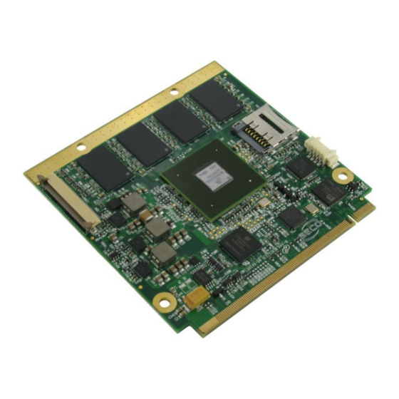
- Page 1 Q7-928 ® Qseven Rel. 2.0 Compliant Module with NXP i.MX6 Processor...
- Page 2 SECO S.r.l. reserves the right to change precise specifications without prior notice to supply the best product possible. For further information on this module or other SECO products, but also to get the required assistance for any and possible issues, please contact us using the dedicated web form available at http://www.seco.com...
- Page 3 ® 3.2.3 Qseven Connector ..........................................23 Chapter 4. Appendices ....................................41 Thermal Design ............................................42 Q7-928 Q7-928 User Manual - Rev. First Edition: 1.0 - Last Edition: 3.0 - Author: S.B. - Reviewed by P.Z Copyright © 2016 SECO S.r.l.
- Page 4 Information and assistance RMA number request Safety Electrostatic Discharges RoHS compliance Terminology and definitions Reference specifications Q7-928 Q7-928 User Manual - Rev. First Edition: 1.0 - Last Edition: 3.0 - Author: S.B. - Reviewed by P.Z Copyright © 2016 SECO S.r.l.
- Page 5 All changes or modifications to the equipment not explicitly approved by SECO S.r.l. could impair the equipment s functionality and could void the warranty Q7-928 Q7-928 User Manual - Rev. First Edition: 1.0 - Last Edition: 3.0 - Author: S.B. - Reviewed by P.Z Copyright © 2016 SECO S.r.l.
- Page 6 A RMA Number will be sent within 1 working day (only for on-line RMA requests). Q7-928 Q7-928 User Manual - Rev. First Edition: 1.0 - Last Edition: 3.0 - Author: S.B. - Reviewed by P.Z Copyright © 2016 SECO S.r.l.
- Page 7 Check carefully that all cables are correctly connected and that they are not damaged. 1.5 Electrostatic Discharges The Q7-928 module, like any other electronic product, is an electrostatic sensitive device: high voltages caused by static electricity could damage some or all the devices and/or components on-board.
- Page 8 Medium Access Controller, the hardware implementing the Data Link Layer of ISO/OSI-7 model for communication systems Mbps Megabits per second Q7-928 Q7-928 User Manual - Rev. First Edition: 1.0 - Last Edition: 3.0 - Author: S.B. - Reviewed by P.Z Copyright © 2016 SECO S.r.l.
- Page 9 Transistor-transistor Logic Universal Serial Bus uSDHC Ultra Secure Digital Host Controller V_REF Voltage reference Pin Q7-928 Q7-928 User Manual - Rev. First Edition: 1.0 - Last Edition: 3.0 - Author: S.B. - Reviewed by P.Z Copyright © 2016 SECO S.r.l.
- Page 10 PCI Express http://www.pcisig.com/specifications/pciexpress ® Qseven Design Guide http://www.sget.org/uploads/media/Qseven_Design_Guide_2_0.pdf ® Qseven specifications http://www.sget.org/uploads/media/Qseven-Spec_2.0_SGET.pdf SATA https://www.sata-io.org Q7-928 Q7-928 User Manual - Rev. First Edition: 1.0 - Last Edition: 3.0 - Author: S.B. - Reviewed by P.Z Copyright © 2016 SECO S.r.l.
- Page 11 SD Card Association https://www.sdcard.org/home SDIO https://www.sdcard.org/developers/overview/sdio SM Bus http://www.smbus.org/specs TMDS http://www.siliconimage.com/technologies/tmds http://www.usb.org/developers/docs/usb_20_070113.zip http://www.nxp.com/products/microcontrollers-and-processors/arm-processors/i.mx-applications-processors-based-on-arm-cores/i.mx-6- NXP i.MX6 processor processors:IMX6X_SERIES Q7-928 Q7-928 User Manual - Rev. First Edition: 1.0 - Last Edition: 3.0 - Author: S.B. - Reviewed by P.Z Copyright © 2016 SECO S.r.l.
- Page 12 Chapter 2. Introduction Technical Specifications Electrical Specifications Mechanical Specifications Block Diagram Q7-928 Q7-928 User Manual - Rev. First Edition: 1.0 - Last Edition: 3.0 - Author: S.B. - Reviewed by P.Z Copyright © 2016 SECO S.r.l.
- Page 13 Interfacing is possible using the direct parallel interface or the integrated MIPI/CSI interface (both available on the same connector). Q7-928 Q7-928 User Manual - Rev. First Edition: 1.0 - Last Edition: 3.0 - Author: S.B. - Reviewed by P.Z Copyright © 2016 SECO S.r.l.
- Page 14 2.2 Technical Specifications Processors ® NXP i.MX6 Family, based on ARM CORTEX-A9 processors 1 x USB OTG interface i.MX6S Solo - Single core up to 1GHz 4 x USB2.0 Host interfaces i.MX6D Dual - Dual core up to 1.2GHz per core Networking i.MX6DL Dual Lite - Dual core up to 1GHz per core i.MX6Q Quad - Quad core up to 1.2GHz per core...
- Page 15 2.3 Electrical Specifications ® According to Qseven specifications, Q7-928 board needs to be supplied only with an external +5V power supply. 5 Volts standby voltage needs to be supplied for working in ATX mode. For Real Time Clock working and CMOS memory data retention, it is also needed a backup battery voltage. All these voltages are supplied directly through card edge fingers (see connector’s pinout).
- Page 16 2.3.3 Inrush current In the following pictures are shown the inrush current relative to the total current drawn by Q7-928 module (with the only exception of the battery absorbed by the battery, drawn from VCC_RTC pin). Measurements have been made on all modules of Qseven i.MX6 family, no significant differences exist between various modules. For this reason, only graphs related to i.MX6 Solo equipped with 512MB of DRAM and i.MX6 Quad with 4GB of DRAM are shown.
- Page 17 The graphs below show the total current absorbed by the Q7-928 module in the boot phase, from POWER ON moment until the completion of the boot. The data shown in figure 3 are related to the module Q7-928 with iMX6 Quad Core and 4 GB of LDDR3 RAM. Measurements are made using Digital Multimeter TTi-1705.
- Page 18 Qseven module. Q7-928 Q7-928 User Manual - Rev. First Edition: 1.0 - Last Edition: 3.0 - Author: S.B. - Reviewed by P.Z Copyright © 2016 SECO S.r.l.
- Page 19 Factory CPLD alternatives +5V_S, +5V_A JTAG Power section ® Texas Instruments Power management MSP430F2232 microcontroller Q7-928 Q7-928 User Manual - Rev. First Edition: 1.0 - Last Edition: 3.0 - Author: S.B. - Reviewed by P.Z Copyright © 2016 SECO S.r.l.
- Page 20 Chapter 3. Introduction Connectors description Q7-928 Q7-928 User Manual - Rev. First Edition: 1.0 - Last Edition: 3.0 - Author: S.B. - Reviewed by P.Z Copyright © 2016 SECO S.r.l.
- Page 21 Card edge golden finger, pin 228 finger, pin 2 finger, pin 1 finger, pin 229 Q7-928 Q7-928 User Manual - Rev. First Edition: 1.0 - Last Edition: 3.0 - Author: S.B. - Reviewed by P.Z Copyright © 2016 SECO S.r.l.
- Page 22 Pins [20÷21; 27÷28]: MIPI CSI additional lanes (only for i.MX6 Dual and i.MX6 Quad) CSI0_DAT17 CSI0_D0_DN CSI0_DAT18 CSI0_D0_DP CSI0_DAT19 CSI0_D1_DN CSI0_DAT10 CSI0_D1_DP Q7-928 Q7-928 User Manual - Rev. First Edition: 1.0 - Last Edition: 3.0 - Author: S.B. - Reviewed by P.Z Copyright © 2016 SECO S.r.l.
- Page 23 GBE_MDI0+ GBE_LINK# GBE_ACT# N.A. N.C. SUS_S5# PWR_MGMT PWR_MGMT WAKE# SUS_S3# PWR_MGMT PWR_MGMT SUS_STAT# PWRBTN# PWR_MGMT Q7-928 Q7-928 User Manual - Rev. First Edition: 1.0 - Last Edition: 3.0 - Author: S.B. - Reviewed by P.Z Copyright © 2016 SECO S.r.l.
- Page 24 N.A. N.C. WDOUT MISC N.A. N.C. N.C. N.A. N.A. N.C. N.C. N.A. N.A. N.C. USB_4_5_OC# Q7-928 Q7-928 User Manual - Rev. First Edition: 1.0 - Last Edition: 3.0 - Author: S.B. - Reviewed by P.Z Copyright © 2016 SECO S.r.l.
- Page 25 TMDS_CLK+ N.C. N.A. HDMI TMDS_CLK- N.C. N.A. HDMI TMDS_TX1+ N.C. N.A. HDMI TMDS_TX1- N.C. N.A. Q7-928 Q7-928 User Manual - Rev. First Edition: 1.0 - Last Edition: 3.0 - Author: S.B. - Reviewed by P.Z Copyright © 2016 SECO S.r.l.
- Page 26 LPC/GPIO LPC/GPIO SERIRQ/GPIO6 LPC_LDRQ#/GPIO7 LPC/GPIO VCC_RTC (+3.3V_A) GP_PWM_OUT2 MISC MISC GP_TIMER_IN GP_PWM_OUT1 MISC SPI_MOSI SPI_CS0# Q7-928 Q7-928 User Manual - Rev. First Edition: 1.0 - Last Edition: 3.0 - Author: S.B. - Reviewed by P.Z Copyright © 2016 SECO S.r.l.
- Page 27 47kΩ resistor; it can be used directly to drive externally a single RESET Signal. In case it is necessary to supply Reset signal to multiple devices, provide for a buffer on the carrier board. Q7-928 Q7-928 User Manual - Rev. First Edition: 1.0 - Last Edition: 3.0 - Author: S.B. - Reviewed by P.Z Copyright © 2016 SECO S.r.l.
- Page 28 The customer acknowledges and agrees to the conditions set forth that these schematics are provided only as an example and that he will conduct an independent analysis and exercise judgment in the use of any and all material. SECO declines all and any liability for use of this or any other material in the customers’...
- Page 29 SATA_ACT#: Serial ATA Activity Led. Open collector output at +3.3V_S voltage. It is driven during SATA drive activity. 10nF AC series decoupling capacitors are placed on each line of SATA differential pairs. Q7-928 Q7-928 User Manual - Rev. First Edition: 1.0 - Last Edition: 3.0 - Author: S.B. - Reviewed by P.Z Copyright © 2016 SECO S.r.l.
- Page 30 Type A receptacles, while USB port #1 implements all the circuitry necessary for USB OTG management. Q7-928 Q7-928 User Manual - Rev. First Edition: 1.0 - Last Edition: 3.0 - Author: S.B. - Reviewed by P.Z Copyright © 2016 SECO S.r.l.
- Page 31 Remov e Jumper to set USB Port #1 in Client mode SUS_S5# R-100K IP4221CZ6-S NC7S00 USB_ID 2N7002 Q7-928 Q7-928 User Manual - Rev. First Edition: 1.0 - Last Edition: 3.0 - Author: S.B. - Reviewed by P.Z Copyright © 2016 SECO S.r.l.
- Page 32 HDA_RST#: AC’97 Codec Reset. Active Low signal Output from the module to the Carrier board, electrical level +3.3V_S. Q7-928 Q7-928 User Manual - Rev. First Edition: 1.0 - Last Edition: 3.0 - Author: S.B. - Reviewed by P.Z Copyright © 2016 SECO S.r.l.
- Page 33 LVDS_B2+/LVDS_B2-: LVDS Channel #1 differential data pair #2. LVDS_B3+/LVDS_B3-: LVDS Channel #1 differential data pair #3. LVDS_B_CLK+/LVDS_B_CLK-: LVDS Channel #1 differential Clock Q7-928 Q7-928 User Manual - Rev. First Edition: 1.0 - Last Edition: 3.0 - Author: S.B. - Reviewed by P.Z Copyright © 2016 SECO S.r.l.
- Page 34 Please refer to the following schematics as an example of implementation of voltage level shifters on the carrier board. Q7-928 Q7-928 User Manual - Rev. First Edition: 1.0 - Last Edition: 3.0 - Author: S.B. - Reviewed by P.Z Copyright © 2016 SECO S.r.l.
- Page 35 BAT54S +3.3V_S +5V_HDMI WHDM-19D5L1BF3U4W +5V_HDMI +5V_S R-1K SL04 BLM18PG121SN1 HDMI_HPD# BAT54S CC-1uF CC-100nF SN74LVC1G14DBVR R-20K Q7-928 Q7-928 User Manual - Rev. First Edition: 1.0 - Last Edition: 3.0 - Author: S.B. - Reviewed by P.Z Copyright © 2016 SECO S.r.l.
- Page 36 (SPI_CS0#) has already been used. It must not be used in case there is only one SPI device. Q7-928 Q7-928 User Manual - Rev. First Edition: 1.0 - Last Edition: 3.0 - Author: S.B. - Reviewed by P.Z Copyright © 2016 SECO S.r.l.
- Page 37 RSTBTN#: Reset Button Input, active low +3.3V_S electrical voltage signal, with 10kΩ pull-up resistor. This signal can be connected to a momentary push-button: Q7-928 Q7-928 User Manual - Rev. First Edition: 1.0 - Last Edition: 3.0 - Author: S.B. - Reviewed by P.Z Copyright © 2016 SECO S.r.l.
- Page 38 GPIO_6: This signal is carried on the pin usually dedicated to LVDS DisplayID DDC Data line. On the Q7-928 module, instead, it can be used as a Generic Purpose I/O, electrical level +3.3V_S with a 4k7Ω pull-up resistor. It is connected to i.MX6 processor’s GPIO_6 pad.
- Page 39 152: HDMI_CTRL_CLK 66: GP0_I2C_CLK I2C_3/I2C-2 0x3C (if MIPI_CSI driver for OV5640 camera is enabled) 68: GP0_I2C_DAT Q7-928 Q7-928 User Manual - Rev. First Edition: 1.0 - Last Edition: 3.0 - Author: S.B. - Reviewed by P.Z Copyright © 2016 SECO S.r.l.
- Page 40 MFG_NCx pins is reserved only for manufacturing phase; it must not be used by the customer. In case it is necessary to trace the software using any JTAG debugger, it is possible to provide Q7-928 module configured with i.MX6 JTAG port accessible on MFG_NCx pins.
- Page 41 Chapter 4. Thermal Design Q7-928 Q7-928 User Manual - Rev. First Edition: 1.0 - Last Edition: 3.0 - Author: S.B. - Reviewed by P.Z Copyright © 2016 SECO S.r.l.
- Page 42 Q7-928 HeatSink (Passive) for COMMERCIAL VERSION and Solo & DualLite INDUSTRIAL, Packaged Q928-DISS-2-I-PK Q7-928 HeatSink (Passive) for Dual & Quad (AUTOMOTIVE & INDUSTRIAL), Packaged Q7-928 Q7-928 User Manual - Rev. First Edition: 1.0 - Last Edition: 3.0 - Author: S.B. - Reviewed by P.Z Copyright © 2016 SECO S.r.l.
- Page 43 Standard Heatspreader dimensions Q7-928 Q7-928 User Manual - Rev. First Edition: 1.0 - Last Edition: 3.0 - Author: S.B. - Reviewed by P.Z Copyright © 2016 SECO S.r.l.
- Page 44 Standard Heatsink dimensions Q7-928 Q7-928 User Manual - Rev. First Edition: 1.0 - Last Edition: 3.0 - Author: S.B. - Reviewed by P.Z Copyright © 2016 SECO S.r.l.
- Page 45 SECO Srl - Via Calamandrei 91 52100 Arezzo - ITALY Ph: +39 0575 26979 - Fax: +39 0575 350210 www.seco.com Q7-928 Q7-928 User Manual - Rev. First Edition: 1.0 - Last Edition: 3.0 - Author: S.B. - Reviewed by P.Z Copyright © 2016 SECO S.r.l.
Need help?
Do you have a question about the Q7-928 and is the answer not in the manual?
Questions and answers