
Related Manuals for Seco COMe-C55-CT6


Summary of Contents for Seco COMe-C55-CT6
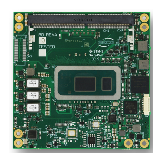
- Page 1 COMe-C55 COM-Express Type 6 Module with the ® Intel generation Core and Celeron 4000 CPUs...
- Page 2 SECO S.p.A. reserves the right to change precise specifications without prior notice to supply the best product possible. For further information on this module or other SECO products, but also to get the required assistance for any and possible issues, please contact us using the dedicated web form available at http://www.seco.com (registration required).
-
Page 3: Table Of Contents
Module connectors ....................................22 3.2.6 BOOT Strap Signals ........................................47 Appendices ....................................48 Thermal Design ........................................... 49 COMe-C55-CT6 COMe-C55-CT6 User Manual - Rev. First Edition: 1.0 - Last Edition: 1.0 - Author: S.B. - Reviewed by L.V. Copyright © 2020 SECO S.p.A. -
Page 4: Introduction
• Safety • Electrostatic Discharges • RoHS compliance • Terminology and definitions • Reference specifications COMe-C55-CT6 COMe-C55-CT6 User Manual - Rev. First Edition: 1.0 - Last Edition: 1.0 - Author: S.B. - Reviewed by L.V. Copyright © 2020 SECO S.p.A. -
Page 5: Warranty
All changes or modifications to the equipment not explicitly approved by SECO S.p.A. could impair the equipment and could void the warranty COMe-C55-CT6 COMe-C55-CT6 User Manual - Rev. First Edition: 1.0 - Last Edition: 1.0 - Author: S.B. - Reviewed by L.V. Copyright © 2020 SECO S.p.A. -
Page 6: Information And Assistance
A RMA Number will be sent within 1 working day (only for on-line RMA requests). COMe-C55-CT6 COMe-C55-CT6 User Manual - Rev. First Edition: 1.0 - Last Edition: 1.0 - Author: S.B. - Reviewed by L.V. Copyright © 2020 SECO S.p.A. -
Page 7: Safety
The COMe-C55-CT6 module is designed using RoHS compliant components and is manufactured on a lead-free production line. It is therefore fully RoHS compliant. COMe-C55-CT6 COMe-C55-CT6 User Manual - Rev. First Edition: 1.0 - Last Edition: 1.0 - Author: S.B. - Reviewed by L.V. Copyright © 2020 SECO S.p.A. -
Page 8: Terminology And Definitions
Low Voltage Differential Signaling, a standard for transferring data at very high speed using inexpensive twisted pair copper cables, usually used for video applications Mbps Megabits per second N.A. Not Applicable N.C. Not Connected COMe-C55-CT6 COMe-C55-CT6 User Manual - Rev. First Edition: 1.0 - Last Edition: 1.0 - Author: S.B. - Reviewed by L.V. Copyright © 2020 SECO S.p.A. - Page 9 Host Controller Interface, Host controller for USB 3.0 ports, which can also manage USB 2.0 and USB1.1 ports COMe-C55-CT6 COMe-C55-CT6 User Manual - Rev. First Edition: 1.0 - Last Edition: 1.0 - Author: S.B. - Reviewed by L.V. Copyright © 2020 SECO S.p.A.
-
Page 10: Reference Specifications
USB 2.0 and USB OTG https://www.usb.org/document-library/usb-20-specification USB 3.0 https://www.usb.org/document-library/usb-32-specification-released-september-22-2017-and-ecns xHCI http://www.intel.com/content/www/us/en/io/universal-serial-bus/extensible-host-controler-interface-usb-xhci.html?wapkw=xhci ® Intel 8th generatio https://ark.intel.com/content/www/us/en/ark/products/codename/135883/whiskey-lake.html#@Embedded 4000 series processor COMe-C55-CT6 COMe-C55-CT6 User Manual - Rev. First Edition: 1.0 - Last Edition: 1.0 - Author: S.B. - Reviewed by L.V. Copyright © 2020 SECO S.p.A. -
Page 11: Overview
• Introduction • Technical Specifications • Electrical Specifications • Mechanical Specifications • Block Diagram COMe-C55-CT6 COMe-C55-CT6 User Manual - Rev. First Edition: 1.0 - Last Edition: 1.0 - Author: S.B. - Reviewed by L.V. Copyright © 2020 SECO S.p.A. -
Page 12: Introduction
Rel.3.0 standard compliant, an open industry standard defined specifically for COMs (computer on modules). Its definition provides the ability to make a smooth transition from legacy parallel interfaces to the newest technologies based on serial buses available. Specifically, COMe-C55-CT6 is a ®... -
Page 13: Technical Specifications
** Temperatures indicated (minimum and maximum) are those measured at any point Optional eMMC 5.1 drive on-board of SECO standard heat-spreader for this product, during any and all times (including Up to 3 x S-ATA Gen3 channels microSD card slot on-board start-up). -
Page 14: Electrical Specifications
Power Consumption COMe-C55-CT6 module, like all COM Express modules, needs a carrier board for its normal working. All connections with the external world come through this carrier board, which provide also the required voltage to the board, deriving it from its power supply source. - Page 15 142mA Suspend to RAM (typical) Soft Off (typical) 63mA 52mA 86mA RTC Power consumption (typical) COMe-C55-CT6 COMe-C55-CT6 User Manual - Rev. First Edition: 1.0 - Last Edition: 1.0 - Author: S.B. - Reviewed by L.V. Copyright © 2020 SECO S.p.A.
-
Page 16: Mechanical Specifications
® the COM Express module. COMe-C55-CT6 COMe-C55-CT6 User Manual - Rev. First Edition: 1.0 - Last Edition: 1.0 - Author: S.B. - Reviewed by L.V. Copyright © 2020 SECO S.p.A. -
Page 17: Block Diagram
USB 3.1 Gen3 ports #0 ÷ #3 USB 2.0 ports #0 ÷ #7 +12V_S +12V_S, +5V_A Power section COMe-C55-CT6 COMe-C55-CT6 User Manual - Rev. First Edition: 1.0 - Last Edition: 1.0 - Author: S.B. - Reviewed by L.V. Copyright © 2020 SECO S.p.A. -
Page 18: Connectors
• Introduction • Connectors description COMe-C55-CT6 COMe-C55-CT6 User Manual - Rev. First Edition: 1.0 - Last Edition: 1.0 - Author: S.B. - Reviewed by L.V. Copyright © 2020 SECO S.p.A. -
Page 19: Introduction
Connector microSD card BIOS restore COM Express COM Express slot switch connector C-D connector A-B COMe-C55-CT6 COMe-C55-CT6 User Manual - Rev. First Edition: 1.0 - Last Edition: 1.0 - Author: S.B. - Reviewed by L.V. Copyright © 2020 SECO S.p.A. -
Page 20: Connectors Description
The two sockets together allow the insertion of up to 2 SO-DIMM modules, for support to dual channel memories. COMe-C55-CT6 COMe-C55-CT6 User Manual - Rev. First Edition: 1.0 - Last Edition: 1.0 - Author: S.B. - Reviewed by L.V. Copyright © 2020 SECO S.p.A. -
Page 21: Microsd Card Slot
3.2.3 microSD Card Slot CPUs used on the COMe-C55-CT6 board provide a SDXC 3.01 compliant controller, that can be used to implement another mass storages media other than the optional internal eMMC and the SATA interfaces (up to three). -push type 3.2.4... -
Page 22: Com Express ® Module Connectors
COMe-C55-CT6 board. Therefore, please refer to the following table for a list of effective signals reported on the connector. For accurate signals description, please consult the following paragraphs. - Page 23 USB_0+ USB1+ VCC_RTC eSPI_EN# N.A. N.C. N.C. N.A. N.A. N.C. SYS_RESET# PWR_MGMT LPC_SERIRQ CB_RESET# PWR_MGMT COMe-C55-CT6 COMe-C55-CT6 User Manual - Rev. First Edition: 1.0 - Last Edition: 1.0 - Author: S.B. - Reviewed by L.V. Copyright © 2020 SECO S.p.A.
- Page 24 LVDS_B2- LVDS eDP/LVDS eDP/LVDS_VDD_EN LVDS_B3+ LVDS LVDS LVDS_A3+ LVDS_B3- LVDS LVDS LVDS_A3- eDP/LVDS_BKLT_EN eDP/LVDS COMe-C55-CT6 COMe-C55-CT6 User Manual - Rev. First Edition: 1.0 - Last Edition: 1.0 - Author: S.B. - Reviewed by L.V. Copyright © 2020 SECO S.p.A.
- Page 25 +12V_RUN +12V_RUN A107 B107 +12V_RUN +12V_RUN A108 B108 +12V_RUN +12V_RUN A109 B109 +12V_RUN A110 B110 COMe-C55-CT6 COMe-C55-CT6 User Manual - Rev. First Edition: 1.0 - Last Edition: 1.0 - Author: S.B. - Reviewed by L.V. Copyright © 2020 SECO S.p.A.
- Page 26 PCIE PCIE PCIE_RX7- PCIE_TX7- PCIE DDI1_HPD N.C. N.A. N.A. N.C. N.C. N.A. N.A. N.C. DDI1_PAIR0+ COMe-C55-CT6 COMe-C55-CT6 User Manual - Rev. First Edition: 1.0 - Last Edition: 1.0 - Author: S.B. - Reviewed by L.V. Copyright © 2020 SECO S.p.A.
- Page 27 N.C. DDI2_PAIR3- PEG_RX0+ PEG_TX0+ PEG_RX0- PEG_TX0- TYPE N.A. TYPE0#: N.C. PEG_LANE_RV# PEG_RX1+ PEG_TX1+ PEG_RX1- PEG_TX1- COMe-C55-CT6 COMe-C55-CT6 User Manual - Rev. First Edition: 1.0 - Last Edition: 1.0 - Author: S.B. - Reviewed by L.V. Copyright © 2020 SECO S.p.A.
- Page 28 N.C. N.C. N.A. N.A. N.C. N.C. N.A. N.A. N.C. N.C. N.A. N.A. N.C. N.C. N.A. COMe-C55-CT6 COMe-C55-CT6 User Manual - Rev. First Edition: 1.0 - Last Edition: 1.0 - Author: S.B. - Reviewed by L.V. Copyright © 2020 SECO S.p.A.
- Page 29 +12V_RUN +12V_RUN C107 D107 +12V_RUN +12V_RUN C108 D108 +12V_RUN +12V_RUN C109 D109 +12V_RUN C110 D110 COMe-C55-CT6 COMe-C55-CT6 User Manual - Rev. First Edition: 1.0 - Last Edition: 1.0 - Author: S.B. - Reviewed by L.V. Copyright © 2020 SECO S.p.A.
- Page 30 3.2.5.1 Audio interface signals The COMe-C55-CT6 module supports HD audio format, thanks to native support offered by the processor to this audio codec standard. Up to 3 HD audio codecs on the carrier board can be supported. Here following the signals related to HD Audio interface: HDA_SYNC: HD Audio Serial Bus Synchronization.
- Page 31 The customer acknowledges and agrees to the conditions set forth that these schematics are provided only as an example and that he will conduct an independent analysis and exercise judgment in the use of any and all material. SECO declines all and any liability for use of this or any other material in the customers’...
- Page 32 3.2.5.4 PCI Express interface signals On COMe-C55-CT6 module, the SoC’s embedded PCH can manage eight PCI Express lane, one of which is used to manage the optional Gigabit Ethernet controller. PCI express Gen3 (8GT/s) is supported. These PCI-express lanes can be switched to support single PCI-e lanes, the third SATA port and the PCI-e Graphics interface.
- Page 33 PEG interface signals In addition to the eight PCI express lanes, described in the previous paragraph, the COMe-C55-CT6 module can offer a PCI-Express x2 or x4 graphics interface (PEG), which can be used for connection of external graphics cards. Such an interface is directly managed by the SoC’s embedded PCH.
- Page 34 2.0 port (i.e. USB 2.0 port#0 must be paired with USB 3.0 port #0 and so on). COMe-C55-CT6 COMe-C55-CT6 User Manual - Rev. First Edition: 1.0 - Last Edition: 1.0 - Author: S.B. - Reviewed by L.V. Copyright © 2020 SECO S.p.A.
- Page 35 0402 ESD9X5.0ST5G USB_4_5_OC# FAULT# RT9728AHGE USB7_P USB7_N USB5_P USB6_P USB5_N USB6_N USB4_P USB4_N DRTR5V0U4LP16 DRTR5V0U4LP16 COMe-C55-CT6 COMe-C55-CT6 User Manual - Rev. First Edition: 1.0 - Last Edition: 1.0 - Author: S.B. - Reviewed by L.V. Copyright © 2020 SECO S.p.A.
- Page 36 Display Port (eDP). Conversely, the LVDS interface, which is frequently used in many application fields, is not directly supported by these CPUs. For this reason, considering that LVDS interface can be multiplexed on the same pin with the eDP interface, on COMe-C55-CT6 module can be implemented an eDP to LVDS bridge (NXP PTN3460), which allow the implementation of a Dual Channel LVDS, with a maximum supported resolution of 1920x1200 @ 60Hz (dual channel mode).
- Page 37 LPC_SERIRQ: LPC Serialised IRQ request, bidirectional line, +3.3V_RUN electrical level with 8k2Ω pull-up resistor. This signal is used only by peripherals requiring Interrupt support. COMe-C55-CT6 COMe-C55-CT6 User Manual - Rev. First Edition: 1.0 - Last Edition: 1.0 - Author: S.B. - Reviewed by L.V. Copyright © 2020 SECO S.p.A.
- Page 38 VGA/CRT displays. As a factory option, however, it is possible to purchase COMe-C55-CT6 modules equipped with a DP to VGA bridge (NXP PTN3356BS), which allow the implementation of a VGA interface with a maximum supported resolution of 2048x1536 @ 50Hz (reduced blanking).
- Page 39 CC-10pF +5V_VGA +3.3V_RUN 74478617 VGA_BLU 1760015-046-R R-150 CC-10pF CC-10pF R-4K7 FDN337 BLM18PG121SN1 VGA_I2C_CK +5V_VGA IP4221CZ6-S COMe-C55-CT6 COMe-C55-CT6 User Manual - Rev. First Edition: 1.0 - Last Edition: 1.0 - Author: S.B. - Reviewed by L.V. Copyright © 2020 SECO S.p.A.
- Page 40 DDI2_PAIR2+ DP2_LANE2+ DP2 Differential pair #2 non-inverting line TMDS2_DATA0+ TMDS2 Differential pair #0 non-inverting line COMe-C55-CT6 COMe-C55-CT6 User Manual - Rev. First Edition: 1.0 - Last Edition: 1.0 - Author: S.B. - Reviewed by L.V. Copyright © 2020 SECO S.p.A.
- Page 41 Please take care of specifying if VGA interface is needed, before placing an order of COMe-C55-CT6 module. COMe-C55-CT6 COMe-C55-CT6 User Manual - Rev. First Edition: 1.0 - Last Edition: 1.0 - Author: S.B. - Reviewed by L.V. Copyright © 2020 SECO S.p.A.
- Page 42 100nF NC7WZ16P6 WDPE-20F3L1BU3 GND_DP0 BLM18PG121SN1J SDM2U40CSP-7B BLM18PG121SN1J +3.3V_RUN GND_DP0 nanoSMDC075F 100nF ESD9X5.0ST5G +5V_RUN Si2312BDS-T1-E3 100K COMe-C55-CT6 COMe-C55-CT6 User Manual - Rev. First Edition: 1.0 - Last Edition: 1.0 - Author: S.B. - Reviewed by L.V. Copyright © 2020 SECO S.p.A.
- Page 43 The schematic on the next page shows an example of implementation of RS-232 transceiver for the Carrier board. COMe-C55-CT6 COMe-C55-CT6 User Manual - Rev. First Edition: 1.0 - Last Edition: 1.0 - Author: S.B. - Reviewed by L.V. Copyright © 2020 SECO S.p.A.
- Page 44 I2C_DAT: general purpose I2C Bus data line. Bidirectional signal, electrical level +3.3V_ALW with a 2K2Ω pull-up resistor. COMe-C55-CT6 COMe-C55-CT6 User Manual - Rev. First Edition: 1.0 - Last Edition: 1.0 - Author: S.B. - Reviewed by L.V. Copyright © 2020 SECO S.p.A.
- Page 45 SUS_STAT#: Suspend status output, active low +3.3V_ALW electrical voltage signal. This output can be used to report to the devices on the carrier board that the COMe-C55-CT6 COMe-C55-CT6 User Manual - Rev. First Edition: 1.0 - Last Edition: 1.0 - Author: S.B. - Reviewed by L.V. Copyright © 2020 SECO S.p.A.
- Page 46 SMB_ALERT#: SM Bus Alert line for System Management. Input signal, electrical level +3.3V_ALW with a 1kΩ pull-up resistor. Any device place on the SM Bus can drive this signal low to signal an event on the bus itself. COMe-C55-CT6 COMe-C55-CT6 User Manual - Rev. First Edition: 1.0 - Last Edition: 1.0 - Author: S.B. - Reviewed by L.V. Copyright © 2020 SECO S.p.A.
-
Page 47: Boot Strap Signals
Configuration straps are signals that, during system reset, are set as inputs (independently by their behaviour during normal operations) in order to allow the proper configuration of the processor / PCH. For this reason, on COMe-C55-CT6 are placed the pull-up or pull-down resistors that are necessary to configure the board properly. -
Page 48: Appendices
• Thermal Design COMe-C55-CT6 COMe-C55-CT6 User Manual - Rev. First Edition: 1.0 - Last Edition: 1.0 - Author: S.B. - Reviewed by L.V. Copyright © 2020 SECO S.p.A. -
Page 49: Thermal Design
Please ask SECO for specific ordering codes. COMe-C55-CT6 COMe-C55-CT6 User Manual - Rev. First Edition: 1.0 - Last Edition: 1.0 - Author: S.B. - Reviewed by L.V. Copyright © 2020 SECO S.p.A. - Page 50 SECO S.p.A. - Via A. Grandi 20 52100 Arezzo - ITALY Ph: +39 0575 26979 - Fax: +39 0575 350210 www.seco.com COMe-C55-CT6 COMe-C55-CT6 User Manual - Rev. First Edition: 1.0 - Last Edition: 1.0 - Author: S.B. - Reviewed by L.V. Copyright © 2020 SECO S.p.A.
Need help?
Do you have a question about the COMe-C55-CT6 and is the answer not in the manual?
Questions and answers