Table of Contents
Advertisement
Use
CC1N7761en
19.02.2007
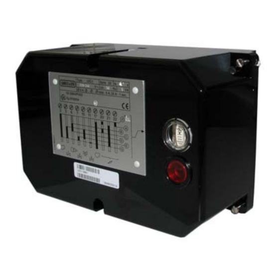
Control Units
Control unit for double- or multiflame supervision of oil, gas or forced draft oil /
gas burners of any fuel throughput, suited for continuous or intermittent opera-
tion.
The LEC1... and this Data Sheet are intended for use by OEMs which integrate the
control units in their products!
The LEC1... is designed for the fully automatic startup and supervision of forced draft
oil or gas burners where flame supervision should or must be carried out by separate
flame safeguards, e.g. with:
•
Double supervision of the main flame or pilot and main flame by 2 identical or dif-
ferent detectors
•
Supervision of forced draft oil / gas burners with different types of detectors, de-
pending on the selected operating mode
•
Multiflame supervision, that is, central and simultaneous control of the startup and
supervision sequence of several burners the flames of which must be individually
supervised by 1 or 2 flame safeguards each
Supplementary Data Sheets
•
LAE10
Data Sheet N7781
•
LFE10
Data Sheet N7781
•
LFE50
Data Sheet N7783
7
LEC1...
Building Technologies
HVAC Products
761
Advertisement
Table of Contents

Related Manuals for Siemens LEC1 Series


Summary of Contents for Siemens LEC1 Series
- Page 1 LEC1... Control Units Control unit for double- or multiflame supervision of oil, gas or forced draft oil / gas burners of any fuel throughput, suited for continuous or intermittent opera- tion. The LEC1... and this Data Sheet are intended for use by OEMs which integrate the control units in their products! The LEC1...
- Page 2 Use (cont´d) The following types of LAE10 For the supervision of oil burners with an active selenium photocell detec- flame safeguards are tor RAR… in intermittent operation available: LFE10 For the supervision with an ionization probe (gas burners) or with UV de- tectors QRA…...
- Page 3 Warning notes To avoid injury to persons, damage to property or the environment, the following warning notes should be observed! Only authorized staff may open, interfere with or modify the unit! • All activities (mounting, installation and service work, etc.) must be performed by qualified staff •...
- Page 4 Electrical connection of the flame detectors It is important to achieve practically disturbance- and loss-free signal transmission: • Never run the detector cable together with other cables – Line capacitance reduces the magnitude of the flame signal – Use a separate cable •...
- Page 5 Disposal notes The unit contains electric and electronic components and must not be disposed of as household waste. Local and currently valid legislation must be observed. Mechanical design The LEC1... as well as the flame safeguards LAE10 and LFE10 are of plug-in design and suitable for mounting in any position on the burner, on control desks or in control panels.
- Page 6 Technical data General unit data Mains voltage AC 220 V -15 %...AC 240 V +10 % AC 100 V -15 %...AC 110 V +10 % Mains frequency 50...60 Hz ±6 % Unit fuse, built-in T6.3H250V to DIN EN 60 127 External fuse max.
- Page 7 Function The following description of the unit’s function refers to the startup and supervision of a single burner. With multiflame supervision, all burners connected to the control unit are put into operation and supervised simultaneously in the same manner. A fault causing lockout of one of the burners therefore results in the shutdown of all burners.
- Page 8 Function (cont´d) Burner startup with In principle, the program sequence is the same as with burner startup without ignition ignition spark proving spark proving. Exceptions: If the UV flame detector does not receive any input signal during the short preigni- tion time (UL2 on «Short preignition»), lockout occurs before any gas is released, i.e.
- Page 9 Adjustment facilities on the unit • Before making any adjustments, disconnect the unit from the mains supply • Loosen all 6 retaining screws and only remove the unit cover • The numbering of the switching cams always starts from the motor •...
- Page 10 Adjustment facilities on the unit (cont´d) Adjusting the safety times «TSA» The safety times are adjusted by setting the red cams of the programming mechanism. Their time marks serve as a setting aid. After the adjustment, the fixing screws of the cams must be tightened very carefully to make any unintentional 7761p07/1296 readjustment impossible.
- Page 11 Basic diagram P(R) EK2* EK1* VI I I VI I I XI I I hr11 P (R) (11) 13 14 hr21 XI I hr12 VI I I I I 7761a01/1102 BV1 (BV1) N (Mp) * Do not press EK… for more than 10 seconds! P(R) LAE10...
- Page 12 Sequence diagram of programming mechanism TSA´ t3 ´ VIII t 1 0 XIII 7761d01/0201 Legend Unit fuse Actuator with limit or auxiliary switches Load relay with contacts «ar...» (refer so «Connection examples») Lockout relay with contacts «br...» a = actuator travels to the OPEN position BV...
- Page 13 Connection examples and sequence diagrams For connection examples and switching program for flame supervision with DETACTOGYR® LFE50..., refer to Data Sheet 7783. Double- or multiflame Startup with long preignition «t3» and checked actuator control. supervision of oil Air pressure supervision from the start to controlled shutdown. burners No load control.
- Page 14 Connection examples and sequence diagrams (cont’d) Double- or multiflame Startup with short preignition (3 seconds) and checked actuator control. supervision of gas Required type of flame safeguards: LFE10... with UV detectors QRA... or ionization burners (expanding probe. flame burners) LEC1... UL.2 19 18 12 11...
- Page 15 Connection examples and sequence diagrams (cont’d) Double- or multiflame supervision of burners for selectable operation with oil or gas (expanding flame burner) Startup with short preignition (3 seconds) and checked actuator control. Control of the 2nd output stage via on / off controller «R2». Required type of flame safeguards: LFE10...
- Page 16 Connection examples and sequence diagrams (cont’d) Double- or multiflame supervision of modulating burners Including checked actuator control. Required type of flame safeguards: For oil LAE10 with active selenium photocell detectors RAR... For gas LFE10 with UV detectors QRA... or ionization probe For oil / gas LFE10 with UV detectors QRA...
- Page 17 To remove the control unit from the plug-in base, loosen only the 4 screws A. To remove the unit cover, also loosen the 2 screws B. Legend Elongated holes for fixing the base Lockout reset button Viewing window ©2007 Siemens Building Technologies HVAC Products GmbH Subject to change! 17/17 Building Technologies CC1N7761en HVAC Products...
Need help?
Do you have a question about the LEC1 Series and is the answer not in the manual?
Questions and answers