Table of Contents
Advertisement
ISO 9001
Use
CC1N7153en
14.10.2002
Oil Burner Controls
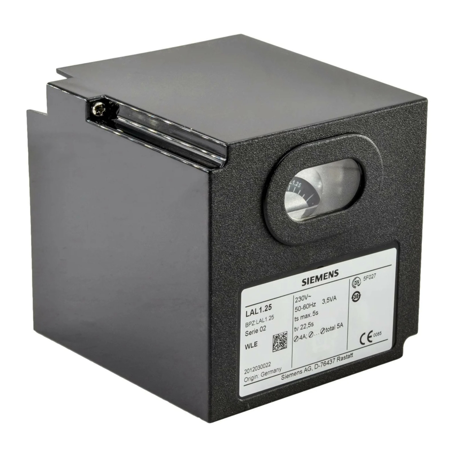
Oil burner controls
·
With or without air pressure supervision for checked air damper control
·
Flame Supervision with
– photoresistive detector QRB1..., or
– blue-flame detector QRC1..., or
– selenium photocell detector RAR...
The LAL... and this Data Sheet are intended for OEMs which integrate the oil
burner controls in their products!
-
For the control and supervision of oil atomization burners
-
For burners of medium to high capacity
For intermittent operation (at least one controlled shutdown every 24 hours)
-
-
Can be universally used with multistage or modulating burners
-
Suited for use with stationary air heaters
Lal1...
- Yellow- and blue-flame burners without air pressure supervision
LAL2...
- Yellow-flame burners with air pressure supervision
LAL3.25
- For special applications, e.g. burners of incinerator plants
(for details, refer to «Type summary» and «Notes»)
Lal4...
- Yellow- and blue-flame burners with air pressure supervision
For burner controls used in connection with burners for continuous operation, refer to
Data Sheet 7785 (LOK16...).
Siemens Building Technologies
HVAC Products
7
153
LAL...
Advertisement
Table of Contents

Related Manuals for Siemens LAL1.25


Summary of Contents for Siemens LAL1.25
- Page 1 (for details, refer to «Type summary» and «Notes») LAL4... - Yellow- and blue-flame burners with air pressure supervision For burner controls used in connection with burners for continuous operation, refer to Data Sheet 7785 (LOK16...). Siemens Building Technologies CC1N7153en HVAC Products 14.10.2002...
- Page 2 10 seconds since this damages the lockout relay in the unit · Fall or shock can adversely affect the safety functions. Such units may not be put into operation, even if they do not exhibit any damage 2/20 Siemens Building Technologies CC1N7153en HVAC Products 14.10.2002...
- Page 3 «B» on the plug-in section of the LAL... must be cut away. Just cutting is not permitted! Š For the permissible lengths and laying of detector cables, refer to «Flame supervision» Mounting notes · Ensure that the relevant safety regulations are complied with 3/20 Siemens Building Technologies CC1N7153en HVAC Products 14.10.2002...
- Page 4 Disposal notes The unit contains electrical and electronic components and may not be disposed of together with household waste. Local and currently valid legislation must be observed. 4/20 Siemens Building Technologies CC1N7153en HVAC Products 14.10.2002...
- Page 5 10 s 10 s Optional Optional 10 s 15 s 15 s 32 s 35 s 12.5 s ¹) With air pressure supervision: From the time the air pressure signal is received 5/20 Siemens Building Technologies CC1N7153en HVAC Products 14.10.2002...
- Page 6 DIN EN 60 721-3-3 Climatic conditions class 3K5 Mechanical conditions class 3M2 Temperature range -20...+60 °C Humidity < 95 % r.h. Condensation, formation of ice and ingress of water are not permitted! 6/20 Siemens Building Technologies CC1N7153en HVAC Products 14.10.2002...
- Page 7 RAR8...: 100 m shield insulated) Shield To termi- nal 23 LAL1... LAL1... LAL2... LAL2... LAL4... LAL3... LAL3... LAL4... 7153v01/0498 7153v05/0498 7153v02/0498 7153v03/0498 µA DC µA DC µA DC µA DC QRB1... QRB1... RAR... QRC1... 7/20 Siemens Building Technologies CC1N7153en HVAC Products 14.10.2002...
- Page 8 – remote emergency shutdown In addition, with LAL2... / LAL3... / LAL4...: – possibility of air pressure supervision with functional test of the air pressure monitor on startup – possibility of semiautomatic burner startup 8/20 Siemens Building Technologies CC1N7153en HVAC Products 14.10.2002...
- Page 9 13 to terminal 14 ® otherwise, the burner control will initiate lockout ® start of the air pressure check Short preignition time: «Z» must be connected to terminal 16, release of fuel via terminal 18 9/20 Siemens Building Technologies CC1N7153en HVAC Products 14.10.2002...
- Page 10 In the event of loss of flame during operation, the LAL... will initiate lockout For automatic start repetition, the clearly marked wire link «B» on the plug- in section of the LAL... must be cut away 10/20 Siemens Building Technologies CC1N7153en HVAC Products 14.10.2002...
- Page 11 During burner off times, the flame supervision circuit is live. When the start position is reached: With LAL1..., a voltage signals is fed to terminal 4 With LAL2... / LAL3... / LAL4..., a voltage signal is fed to terminal 12 11/20 Siemens Building Technologies CC1N7153en HVAC Products 14.10.2002...
- Page 12 – After rectification of a fault that led to shutdown – After each power failure During this period of time, power is only fed to terminals 7 and 9...11. · Then, the LAL..will program a new burner startup sequence 12/20 Siemens Building Technologies CC1N7153en HVAC Products 14.10.2002...
- Page 13 Connection diagrams (for variants, refer to «Connection examples») LAL1... 16 17 11 10 1(3) QRB1... 7153a01/0398 QRC1... LAL2... / LAL3... 16 17 18 11 10 1(3) QRB1... 7153a02/0498 RAR... 13/20 Siemens Building Technologies CC1N7153en HVAC Products 14.10.2002...
- Page 14 Connection diagrams (for variants, refer to «Connection examples») LAL4... 16 17 18 11 10 1(3) QRB1... 7153a04/0498 QRC1... 14/20 Siemens Building Technologies CC1N7153en HVAC Products 14.10.2002...
-
Page 15: Connection Diagrams
EK2* 7153a08/0598 Do not press the lockout reset button for more than 10 seconds! For the connection of the safety shutoff valve, refer to the plant diagram provided by the burner supplier. 15/20 Siemens Building Technologies CC1N7153en HVAC Products 14.10.2002... - Page 16 For the connection of the safety shutoff valve, refer to the plant diagram provided by the burner supplier. Sequence diagram Control output at terminal: t3´ VIII t10* XIII 7153d01e/0402 Positions of lockout indicator * These data do not apply to LAL1... 16/20 Siemens Building Technologies CC1N7153en HVAC Products 14.10.2002...
- Page 17 Interval to the OPEN command for the air damper Postpurge time (with «M2») Not with all LAL…: For self-shutdown Interval between start command and voltage of the sequence switch at terminal 7 (start delay time for «M2») 17/20 Siemens Building Technologies CC1N7153en HVAC Products 14.10.2002...
- Page 18 «W» responds. «L3» indicates when the burner is ready for startup. It extinguishes shortly after the burner is started up. For other connections, refer to «Con- nection diagrams». 18/20 Siemens Building Technologies CC1N7153en HVAC Products 14.10.2002...
- Page 19 During burner off times, the air damper is fully closed. When using actuators with changeover end switch «z» for the CLOSED position, terminals 10 and 11 must be interconnected. For other connections, refer to «Connection diagrams». 100% min. 0... 7153a10/0498 19/20 Siemens Building Technologies CC1N7153en HVAC Products 14.10.2002...
- Page 20 LAL... with plug-in base AGM... 18,9 7153m02/0396 27,5 27,5 18,5 13,5 Plug-in base AGM... 5,2x6,7 (Pg11 or M16 threads) 18,9 5,2x6,7 12,8 51,5 51,5 ã 2002 Siemens Building Technologies Subject to change! 20/20 Siemens Building Technologies CC1N7153en HVAC Products 14.10.2002...
Need help?
Do you have a question about the LAL1.25 and is the answer not in the manual?
Questions and answers