Table of Contents
Advertisement
Quick Links
Iwaki
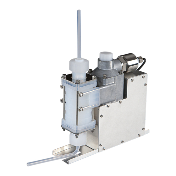
Photoresist Dispensing Pump
PDS-105 RA/RB
Instruction manual
Thank you for choosing our product.
Please read through this instruction manual before use.
This instruction manual describes important precautions and instruc-
tions for the product. Always keep it on hand for quick reference.
©2011 IWAKI CO., LTD.
Advertisement
Table of Contents

Subscribe to Our Youtube Channel
Related Manuals for IWAKI PUMPS PDS-105 RA


Summary of Contents for IWAKI PUMPS PDS-105 RA
- Page 1 Iwaki Photoresist Dispensing Pump PDS-105 RA/RB Instruction manual Thank you for choosing our product. Please read through this instruction manual before use. This instruction manual describes important precautions and instruc- tions for the product. Always keep it on hand for quick reference.
-
Page 2: Order Confirmation
Order confirmation Open the package and check that the product conforms to your order. If any problem or inconsistency is found, immediately contact your distributor. a. Check if the delivery is correct. Check the nameplate to see if the information such as model codes and production number are as or- dered. -
Page 3: Table Of Contents
Contents Order confirmation ............................2 Safety instructions ..............5 Warnings ................................ 6 Cautions ................................. 7 Precautions for use ............................8 Overview ..................9 Introduction ..............................9 Pump structure & Operating principle ......................9 Discharge process ..........................9 Suction process ..........................10 Identification codes ............................ - Page 4 Maintenance ................17 Troubleshooting ............................17 Inspection ..............................18 Daily inspection ............................18 Wear part list ............................18 Specification/Outer dimension ........................19 Specification ............................. 19 Pump ..............................19 Stepping motor ............................ 20 Encoder (RB type) ..........................20 Home sensor ............................20 Pressure sensor ..........................
-
Page 5: Safety Instructions
Safety instructions Read through this section before use. This section describes important information for you to prevent personal injury or property damage. ■ Symbols In this instruction manual, the degree of risk caused by incorrect use is noted with the follow- ing symbols. -
Page 6: Warnings
WARNING Turn off power before work Risk of electrical shock. Be sure to turn off power to stop the pump and related devices before service is performed. Let other people know about the situation by displaying a notice such as "POWER OFF (Maintenance)" Requirement near the power switch. -
Page 7: Cautions
CAUTION Qualified personnel only The pump should be handled or operated by qualified personnel with a full understanding of the pump. Any person not familiar with the product Requirement should not take part in the operation or maintenance of the pump. Use specified power only Do not apply any power other than that specified on the nameplate. -
Page 8: Precautions For Use
Precautions for use • Electrical work should be performed by a qualified electrician. Otherwise, personal injury or property damage could result. Caution • Do not install the pump: –In a flammable atmosphere. –In a dusty/humid place. Caution – In a corrosive atmosphere. •... -
Page 9: Overview
Overview Pump characteristics, features and part names are described in this sec- tion. Introduction Pump structure & Operating principle The rotational motion of the stepping motor is changed to linear motion by the direct drive unit. Liquid is loaded into the pump head and then delivered to a discharge line as the bellows reciprocates. Principle of operation ●... -
Page 10: Suction Process
■ Suction process Introduction... -
Page 11: Identification Codes
Identification codes Each code represents the following information. PDS - 1 05 RA - K P W2 a. Series name b. Product classification 1: Pump c. Flow rate 05: 5.0ml/shot (max discharge capacity) d. Drive unit RA: Compact type RB: With an encoder (line driver) e. -
Page 12: Installation
Installation This section describes the installation of the pump, piping and wiring. Read through this section before work. Points to be observed Observe the following points when installing the pump. • Be sure to turn off power to stop the pump and related devices before service is per- formed. -
Page 13: Installation/Piping/Wiring
Installation/Piping/Wiring Points to be observed Observe the following points during wiring work. • Electrical work should be performed by a qualified electrician. Always observe applica- ble codes or regulations. • Do not perform wiring work while the power is on. Otherwise, an electrical shock or short circuit may result. -
Page 14: Wiring
Wiring See the table below for wiring with each device. ■ A connector (signal) Pin number Terminal assignment Encoder A phase + Line driver output Encoder A phase - Line driver output Encoder B phase + Line driver output Encoder B phase - Line driver output GND (common) Sensor output (open collector) 5-24VDC (home sensor power) -
Page 15: Operation
Operation This section describes pump operation. Observe instructions in this manu- al. See manufacturer's instruction manual for the motor driver. Pump setting First, program operation of the pump. Pulse input direction & Motor rotation The pump lets out liquid at the input of the CCW direction command pulse and takes in liquid at the input of the CW direction command pulse. -
Page 16: Motor Waiting Time
Motor waiting time A discharge and a suction process are repeated in turn during operation, changing the rotational direction of the motor. A motor waiting time until a shift of a rotational direction needs to be programmed before operation. See the formula below for detail. T >= t/2 T: Waiting time t : Discharge time or suction time, whichever is longer. -
Page 17: Maintenance
Maintenance This section describes troubleshooting, inspection, specification and dimensions. Points to be observed Observe the following points during maintenance work. • Follow instructions in this manual for replacement of wear parts. Do not disassemble the pump beyond the extent of the instructions. •... -
Page 18: Inspection
Inspection Perform daily inspection to keep pump performance and safety. Daily inspection Check for a leak or any other abnormality during operation. Upon sensing abnormality, stop operation immedi- ately and remove problems according to "Troubleshooting". Wear part list To run the pump for a long period, wear parts need to be replaced periodically or when pump performance has reduced. -
Page 19: Specification/Outer Dimension
Specification/Outer dimension Specification Information in this section is subject to change without notice. ■ Pump Item Spec Max discharge capacity 5.0 [ml/shot] Max discharge pressure* 150 [kPa] 4&6 Pressure resistance 300 [kPa] Discharge speed 0.1-4.0 [ml/sec] Suction speed* 0.1-3.0 [ml/sec] Resolution 0.01 [ml] Discharge accuracy... -
Page 20: Stepping Motor
■ Stepping motor Items Spec Manufacturer ORIENTAL MOTOR Co, Ltd. Model PK545-NB or equivalent Maximum holding torque 0.23 N·m Rated current 0.75A/Phase Step angle 0.72° Insulation resistance B class (130ºC) The above date is based on use of an ORIENTAL MOTOR CSD5807N2-P driver. ■... -
Page 21: Outer Dimension
Outer dimension ■ PDS-105R A/B 1/4" PFA tube (2000) (189) (100) 213.5 1/4" PFA tube Specification/Outer dimension... -
Page 22: Part Names
Part names ■ PDS-105R A/B Name Q'ty Material Remarks Pump head unit In port unit Out port In connecting port Out connecting port O ring Kalrez® AS568-129 Valve cap Valve seat PCTFE Valve guide PTFE Valve RUBY 3/16" Valve gasket PTFE Valve case PCTFE... - Page 23 Specification/Outer dimension...
- Page 24 IWAKI Norge AS TEL : (47)23 38 49 00 FAX : 23 38 49 01 China IWAKI Pumps (Guandong) Co., Ltd. TEL : (86)750 3866228 FAX : 750 3866278 Singapore IWAKI Singapore Pte. Ltd. TEL : (65)6316 2028 FAX : 6316 3221 China GFTZ IWAKI Engineering &...
Need help?
Do you have a question about the PDS-105 RA and is the answer not in the manual?
Questions and answers