Advertisement
Quick Links
MANUFACTURED BY:
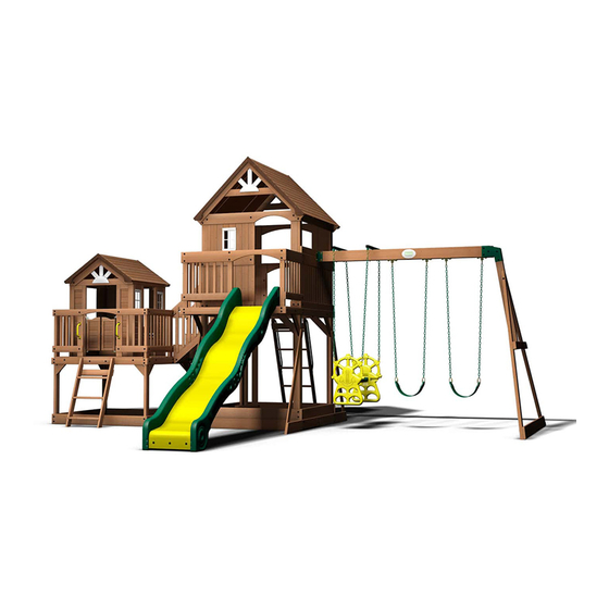
Wooden Swing Set
Backyard Discovery
3305 Airport Drive
Pittsburg, KS 66762
Model # 1606036
Owner's Manual & Assembly Instructions
800-856-4445
average 2 person assembly time
assembly time may vary based on skill level
For the most up to date assembly manual,
to register your set, or to order replacement parts please visit
www.backyarddiscovery.com
SAVE THIS ASSEMBLY MANUAL FOR FUTURE REFERENCE IN THE EVENT THAT
YOU NEED TO ORDER REPLACEMENT PARTS.
Made in China |
Advertisement

Subscribe to Our Youtube Channel
Related Manuals for Backyard Discovery MALIBU


Summary of Contents for Backyard Discovery MALIBU
- Page 1 MANUFACTURED BY: Wooden Swing Set Backyard Discovery 3305 Airport Drive Pittsburg, KS 66762 Model # 1606036 Owner's Manual & Assembly Instructions 800-856-4445 average 2 person assembly time assembly time may vary based on skill level For the most up to date assembly manual, to register your set, or to order replacement parts please visit www.backyarddiscovery.com...
- Page 2 INSTALLATION SERVICES AVAILABLE! Need a helping hand? Let our team of professionals handle the installation for you! *Installation services are only available to U.S. customers. With Go Configure, we bring you 18 years of experience right to your doorstep. We service a wide array of indoor and outdoor recreation products that most consumers don’t have the time or ability to deliver &...
- Page 3 Please Read This Before Starting Assembly MISSING A PART? CALL US BEFORE GOING BACK TO THE STORE Th e store where you made your purchase does not stock parts for this item. If you have assembly questions or you are missing or have damaged parts, please call you can also visit www.backyarddiscovery.com or e-mail customerservice@backyarddiscovery.com...
- Page 4 Botanical, Adventure Playsets, and Leisure Time Products. Backyard Discovery warrants that this product is free from defect in materials and workmanship for a period of one (1) year from the original date of purchase. Th is one (1) year warranty covers all parts including wood, hardware, and accessories. All wood carries a fi ve (5) year pro-rated warranty against rot and decay. Refer to the schedule below for charges associated with replacement of parts under this Limited Warranty.
- Page 5 Operating Instructions and Safety Warnings WARNING: BURN HAZARD • Pay special attention to plastic and metal surfaces as they may be hot enough to cause burns. • Always check the temperature of the product before NOTE: letting your children play on it. •...
- Page 6 Please Read This Before Starting Assembly Positioning Your Playcenter Suggested Playground Surfacing • Th e playcenter is designed to be installed on a level • Do not install home playground equipment over surface by an adult with an adult helper. Place concrete, asphalt, packed earth, grass, carpet, or any in a fl at area of your yard to minimize ground other hard surface.
- Page 7 Please Read This Before Starting Assembly APPENDIX A The following information is from the United States X3.1.3.2 Do not install loose-fi ll surfacing over hard surfaces such as concrete or asphalt. Consumer Product Safety Commission’s Information X3.1.4 Poured-In-Place Surfaces or Pre-Manufactured Sheet for playground surfacing material;...
- Page 8 Check all moving parts including swing seats, third party person or service to assemble this product. ropes, cables, and chains for wear, rust, or other Backyard Discovery assumes no responsibility or deterioration. Replace as needed. liability for any charge incurred by the Customer for any assembly services’...
- Page 9 About Our Wood Backyard Discovery uses 100% Cedar (C. Lanceolata) wood. Although we take great care in selecting the best quality lumber available, wood is still a product of nature and susceptible to weathering which can change the appearance of your set.
- Page 10 Assembly Tips Protrusion Hazard Incorrect Correct If you see exposed threads and your bolt protrudes beyond the T-Nut you may have over tightened the bolt or used incorrect hardware. If you’ve overtightened, remove the bolt and add washers to eliminate the protrusion.
- Page 11 Assembly Tips ASSEMBLY TIP: Keep an eye out for these boxes which will contain helpful pictures and information making the assembly process as quick and painless as possible. Sorting Wood When removing the wood from the boxes we recommend arranging them by part number before you begin assembly.
- Page 12 Tools Required for Installation: (These are the tools that are generally required for assembly of our outdoor products. These tools are not included with the outdoor product purchase.) (Square) (Level 24") (Open End Wrenches 1/2") (Tape Measure) (5/16" , 7/16", 1/8" & 3/8" Drill Bits) (Phillips Screw Driver) (Claw Hammer) (Rubber Mallet - Optional)
- Page 13 Basic Setup Dimensions Place the set on level ground, not less than 6 ft [2 m] from any structure or obstruction such as a fence, garage, house, overhanging branches, laundry lines, or electrical wires. Safe Play Zone 6'-0" 28'-5 1/4" 16'-5 1/4"...
- Page 14 Parts Identification Wood Components (NOT TO SCALE) A50 - SWING BEAM - W4L06616 3 3/8"x5 1/4"x89 1/2" (86x134x2274) E1 - LEFT FRONT UPRIGHT - W4L06385 1 3/8"x3 3/8"x60 5/8" (36x86x1540) E2 - RIGHT FRONT UPRIGHT - W4L06386 1 3/8"x3 3/8"x60 5/8" (36x86x1540) E3 - RIGHT REAR UPRIGHT - W4L06387 1 3/8"x3 3/8"x67 1/2"...
- Page 15 Parts Identification Wood Components (NOT TO SCALE) E51 - ANGLE BRACE - W4L06614 1 3/8"x3 3/8"x88 3/4" (36x86x2254) F1 - RIGHT DECK UPRIGHT - W4L06440 1 3/8"x2 3/8"x30 3/8" (36x60x770) F2 - DECK UPRIGHT - W4L06441 1 3/8"x2 3/8"x30 3/8" (36x60x770) F3 - LEFT DECK UPRIGHT - W4L06445 1 3/8"x2 3/8"x30 3/8"...
- Page 16 Parts Identification Wood Components (NOT TO SCALE) H8 - FLOOR RAIL - W4L06437 1"x3 3/8"x52 1/2" (24x86x1335) H9 - FLOOR RAIL - W4L06438 1"x3 3/8"x54 1/2" (24x86x1383) H10 - FLOOR RAIL - W4L06439 1"x3 3/8"x54 1/2" (24x86x1383) H11 - DECK BRACE - W4L06448 1"x3 3/8"x17 7/8"...
- Page 17 Parts Identification Wood Components (NOT TO SCALE) J2 - COUNTER TOP SUPPORT - W4L06411 1"x2 3/8"x5 7/8" (24x60x150) J3 - SEAT SUPPORT - W4L06417 1"x2 3/8"x8 3/8" (24x60x214) J4 - FLOOR SUPPORT - W4L06454 1"x2 3/8"x52 1/2" (24x60x1335) J9 - SUPPORT BOARD - W4L06064 1"x2 3/8"x3"...
- Page 18 Parts Identification Wood Components (NOT TO SCALE) K11 - WALL RAIL - W4L06470 5/8"x5 1/4"x3 3/8" (16x134x86) K12 - ARCHED WALL RAIL - W4L06471 5/8"x5 1/4"x54 1/8" (16x134x1375) K13 - WALL RAIL - W4L06473 5/8"x5 1/4"x28 5/8" (16x134x728) K14 - WALL RAIL - W4L06474 5/8"x5 1/4"x4 3/4"...
- Page 19 Parts Identification Wood Components (NOT TO SCALE) L5 - LONG SIDE BOARD - W4L06421 5/8"x4 3/8"x15" (16x112x380) L6 - SHORT SIDE BOARD - W4L06422 5/8"x4 3/8"x7 1/2" (16x112x192) L7 - ARCHED SIDE BOARD - W4L06423 5/8"x4 3/8"x15" (16x112x380) L8 - SEAT BOARD - W4L06418 1"x4 3/8"x36 3/4"...
- Page 20 Parts Identification Wood Components (NOT TO SCALE) M12 - REAR CORNER BOARD - W4L06447 5/8"x3 3/8"x45 3/4" (16x86x1163) M13 - ANGLE BRACE - W4L06449 5/8"x3 3/8"x55 7/8" (16x86x1420) M14 - FLOOR BOARD - W4L06452 5/8"x3 3/8"x21 1/2" (16x86x546) M15 - FLOOR BOARD - W4L06453 5/8"x3 3/8"x21 1/2"...
- Page 21 Parts Identification Wood Components (NOT TO SCALE) M27 - WALL BOARD - W4L06534 5/8"x3 3/8"x48" (16x86x1219) M28 - WALL BOARD - W4L06535 5/8"x3 3/8"x29 7/8" (16x86x760) M29 - WALL BOARD - W4L06536 5/8"x3 3/8"x8 1/4" (16x86x210) M30 - WALL BOARD - W4L06537 5/8"x3 3/8"x26 7/8"...
- Page 22 Parts Identification Wood Components (NOT TO SCALE) N1 - TIE STRAP - W4L05043 5/8”x2”x3 1/8” (16x50x80) N2 - REAR WINDOW SHELF - W4L06414 5/8"x2 3/8"x18 7/8" (16x60x479) N3 - LEFT WINDOW SHELF - W4L06415 5/8"x2 3/8"x19 1/8" (16x60x485) N4 - SEAT CLEAT - W4L06419 5/8"x2 3/8"x9"...
- Page 23 Parts Identification Wood Components (NOT TO SCALE) T3 - SUPPORT BOARD - W4L06444 1"x1 3/8"x49 5/8" (24x34x1262) Y1 - STAIR BOARD - W4L06621 5/8"x4"x20 5/8" (16x102x525) Y2 - STAIR BOARD - W4L06620 5/8"x2 5/8"x20 5/8" (16x67x525) WP2 - REAR RIGHT CORNER PANEL - W2A01914 WP1 - FRONT RIGHT CORNER PANEL - W2A01911 WP3 - FRONT LEFT CORNER PANEL - W2A01917 WP4 - REAR LEFT CORNER PANEL - W2A01920...
- Page 24 Parts Identification Wood Components (NOT TO SCALE) WP5 - REAR CENTER PANEL - W2A01922 WP6 - LEFT CENTER PANEL - W2A01924 WP8 - HEADER ASSEMBLY - W2A01926 SR1 - STAIR STRINGER ASSEMBLY - W2A01937 RP1 - LOWER ROOF PANEL - W2A01929 RP2 - UPPER ROOF PANEL - W2A01930 RP3 - LOWER ROOF PANEL - W2A01932 RP4 - UPPER ROOF PANEL - W2A01936...
- Page 25 Parts Identification Hardware (11) - BOLT WH 5/16x2-1/2 BLK - H100194 - BOLT WH 5/16x1/2 - H100115 (30) - BOLT WH 5/16x3/4 - H100222 - BOLT WH 5/16x2-1/4 BLK - H100205 (76) - BOLT WH 5/16x1 3/4 BLK - H100378 - BOLT WH 5/16x2 BLK - H100457 (18) - BOLT WH 5/16x1 1/2 BLK - H100407...
- Page 26 Parts Identification Hardware CR - SCREW PFH 8x3/4 - H100121 VQ - LAG SCREW WH 5/16x2-1/2 BLK - H100197 (22) BN - SCREW PFH 8x1 - H100085 (334) BR - SCREW PFH 8x1 1/8 - H100088 (30) - LAG SCREW WH 5/16x2 BLK - H100458 (132) BQ - SCREW PFH 8x1 1/4 - H100087 (238)
- Page 27 Parts Identification Hardware (10) C - NUT BARREL WH 5/16x1 1/2 - H100006 VL - NUT BARREL WH 5/16x1-1/2 BLK - H100193 (18) VK - NUT BARREL WH 5/16x7/8 BLK - H100192 (14) - NUT BARREL WH 5/16x5/8 BLK - H100469 (11) - NUT BARREL WH 1/4x7/8 BLK - H100399 - NUT BARREL WH 1/4x5/8 BLK - H100404...
- Page 28 Parts Identification Hardware (235) VR - WASHER LOCK EXT 8x19 BLK - H100198 AC - WASHER LOCK EXT 8x19 - H100030 CF - WASHER LOCK INT 10x18 - H100107 (27) VS - WASHER LOCK EXT 12x19 BLK - H100199 BX - WASHER SPLIT 5/16 - H100095 (16) - WASHER LOCK EXT 8x15 BLK - H100400 (30)
- Page 29 Parts Identification Accessories (NOT TO SCALE) DW - SLIDE SUPPORT TUBE 21.34x505 - A100034 21.34 OD x 2.77 W x 505 EW - GLIDER SUPPORT BYD GREEN - A100065 GD - L BRACKET 66x66x127 - A100140 - 90° L-BRACKET - BLK - A4M00555 TZ - L BRACKET 2.5x38x50x55 - A100340 EX - GLIDER BUSHING BYD GREEN - A100066 EY - TUBING CAP GLIDER SUPPORT - A100067...
- Page 30 Parts Identification Accessories (NOT TO SCALE) VB - PLASTIC SUNBURST - A100361 TC - SWING BEAM EXTENSION BRACKET-RIGHT - A100326 TB - SWING BEAM EXTENSION BRACKET-LEFT - A100325 - STOVE KIT - A6P00025 - FAUCET KIT - A6P00024 - SURFACE MOUNT BASIN - A6P00032 KE - SLIDE BED 10' YELLOW - A100197 - SEAT CUSHION - A6P00107 - WINDOW (FLAT PACK) - A6P00019...
- Page 31 H79 - LEFT UPRIGHT - W4L06611 H76 - LADDER RUNG - W4L06609 1"x3 3/8"x38 3/8" (24x86x976) 1"x3 3/8"x18 1/8" (24x86x460) 3 FOOT LADDER ASSEMBLY STEP 1 SCREW PFH SCREW PFH 8x2 (6 PLCS)
- Page 32 H80 - RIGHT UPRIGHT - W4L06612 1"x3 3/8"x38 3/8" (24x86x976) 3 FOOT LADDER ASSEMBLY STEP 2 SCREW PFH SCREW PFH 8x2 (6 PLCS)
- Page 33 M73 - REAR SUPPORT - W4L06608 5/8"x3 3/8"x19 1/4" (16x86x488) 3 FOOT LADDER ASSEMBLY STEP 3 SCREW PFH SCREW PFH 8x2 (4 PLCS) 1 1/4...
- Page 34 M110 - ATTACHMENT BOARD - W4L06610 5/8"x3 3/8"x19 1/4" (16x86x488) 3 FOOT LADDER ASSEMBLY STEP 4 SCREW PFH 8x2 (4 PLCS) M110 SCREW PFH FLUSH...
- Page 35 H76 - LADDER RUNG - W4L06609 H77 - LEFT UPRIGHT - W4L06606 1"x3 3/8"x18 1/8" (24x86x460) 1"x3 3/8"x64 3/8" (24x86x1634) 5 FOOT LADDER ASSEMBLY STEP 1 SCREW PFH 8x2 (10 PLCS) SCREW PFH (10)
- Page 36 H78 - RIGHT UPRIGHT - W4L06607 1"x3 3/8"x64 3/8" (24x86x1634) 5 FOOT LADDER ASSEMBLY STEP 2 SCREW PFH (10) SCREW PFH 8x2 (10 PLCS)
- Page 37 M73 - REAR SUPPORT - W4L06608 M110 - ATTACHMENT BOARD - W4L06610 5/8"x3 3/8"x19 1/4" (16x86x488) 5/8"x3 3/8"x19 1/4" (16x86x488) 5 FOOT LADDER ASSEMBLY STEP 3 M110 SCREW PFH 8x2 SCREW PFH (8 PLCS) FLUSH 1 1/4...
- Page 38 JV - HAND GRIP GREEN 816 c/c - A100134 5 FOOT LADDER ASSEMBLY STEP 4 LAG SCREW WH 1/4x1-1/2 (4 PLCS) LAG SCREW WH 1/4x1-1/2...
- Page 39 A50 - SWING BEAM - W4L06616 3 3/8"x5 1/4"x89 1/2" (86x134x2274) TC - SWING BEAM EXTENSION BRACKET-RIGHT - A100326 GD - L BRACKET 66x66x127 - A100140 TB - SWING BEAM EXTENSION BRACKET-LEFT - A100325 5 FT SWING BEAM ASSEMBLY STEP 1 NUT LOCK 5/16 BLK (2 PLCS) WASHER FLAT 8x27 BLK...
- Page 40 E51 - ANGLE BRACE - W4L06614 SP50 - SWING BEAM SUPPORT - W4L06617 1 3/8"x3 3/8"x88 3/4" (36x86x2254) 3 3/8"x3 3/8"x49 3/8" (86x86x1254) G50 - GROUND BOARD - W4L06613 E50 - END SUPPORT - W4L06615 1"x5 1/4"x86 3/4" (24x134x2202) 1 3/8"x3 3/8"x44 1/8" (36x86x1120) STEP 2 5 FT SWING BEAM ASSEMBLY BOLT WH...
- Page 41 STEP 3 5 FT SWING BEAM ASSEMBLY SWING BEAM ASSEMBLY BOLT WH 5/16x3 BLK NUT BARREL WH 5/16x7/8 NUT BARREL WH 5/16x7/8 BLK (2 PLCS) SWING BEAM END ASSEMBLY BOLT WH 5/16x3 BLK (2 PLCS)
- Page 42 - SWING HANGER - A4M00505 STEP 4 5 FT SWING BEAM ASSEMBLY T-NUT 3/8 WASHER FLAT 11x25 WASHER LOCK INT 10x18 T-NUT 3/8 (8 PLCS) WASHER LOCK INT 10x18 SWING HANGER (8 PLCS) (4 PLCS) BOLT HEX 3/8x5 3/4 (8 PLCS)
- Page 43 EW - GLIDER SUPPORT BYD GREEN - A100065 EX - GLIDER BUSHING BYD GREEN - A100066 EY - TUBING CAP GLIDER SUPPORT - A100067 STEP 5 5 FT SWING BEAM ASSEMBLY BOLT WH 5/16x5 3/4 6" SWING HANGER QUICK LINK GLIDER SUPPORT BYD GREEN (2 PLCS) NUT LOCK...
- Page 44 EZ - CHAIN GREEN 51.25" - A100068 DN - GLIDER SEAT DARK GREEN - A100025 FA - QUICK LINK - A100069 DO - CAPTAINS GLIDER ARM YELLOW - A100026 5' CAPTAINS GLIDER ASSEMBLY BOLT WH 5/16x5 3/4 NUT LOCK 5/16 WASHER FLAT 8x27...
- Page 45 M70 - SLIDE BED SUPPORT - W100935 5/8"x3 3/8"x19 7/8" (16x86x505) KE - SLIDE BED 10' YELLOW - A100197 SLIDE ASSEMBLY STEP 1 BOLT WH 5/16x1/2 T-NUT 5/16 SLIDE BED 10' YELLOW (SEE SLIDE ASSEMBLY INSTALLATION STEP FOR DECK MOUNTING HOLE DRILLING LOCATIONS).
-
Page 46: Table Of Contents
DS - SLIDE RAIL 10' BOTTOM RIGHT GREEN - A100031 TR - SLIDE RAIL 10' TOP RIGHT GREEN - A100033 DR - SLIDE RAIL 10' BOTTOM LEFT GREEN - A100030 DT - SLIDE RAIL 10' TOP LEFT GREEN - A100032 SLIDE ASSEMBLY STEP 2 REPEAT ON OTHER SIDE, MAKING A LEFT AND RIGHT ASSEMBLY. -
Page 47: Slide Assembly Step
DW - SLIDE SUPPORT TUBE 21.34x505 - A100034 21.34 OD x 2.77 W x 505 SLIDE ASSEMBLY STEP 3 PLACE (1) SLIDE RAIL ASSEMBLY ON A FLAT SURFACE AND BEGIN INSERTING SLIDE BED AT THE BOTTOM OF THE SLIDE RAIL (FIG. 1). HAVE A HELPER BEND THE SLIDE BED TOWARDS THE TOP OF THE SLIDE AND INSERT THE BED INTO THE SLIDE CAVITY. - Page 48 SLIDE ASSEMBLY STEP 4 ONCE THE SLIDE BED, SUPPORT TUBES, AND SUPPORT BOARD ARE COMPLETELY IN THE CAVITY AND SUPPORT POCKET, SECURE USING 2 1/2" SCREWS AT EACH OF THE PILOT HOLE LOCATIONS AS SHOWN. REPEAT PROCESS FOR OPPOSITE SLIDE RAIL. SCREW PFH (38) 8x2 1/2...
-
Page 49: Washer Lock Ext 8X19
E2 - RIGHT FRONT UPRIGHT - W4L06386 H4 - FLOOR RAIL - W4L06396 1 3/8"x3 3/8"x60 5/8" (36x86x1540) 1"x3 3/8"x54 7/8" (24x86x1394) E3 - RIGHT REAR UPRIGHT - W4L06387 1 3/8"x3 3/8"x67 1/2" (36x86x1715) K2 - GROUND BOARD - W4L06390 5/8"x5 1/4"x56 1/8"... - Page 50 E1 - LEFT FRONT UPRIGHT - W4L06385 H2 - FLOOR RAIL - W4L06392 1 3/8"x3 3/8"x60 5/8" (36x86x1540) 1"x3 3/8"x54 7/8" (24x86x1394) E4 - LEFT REAR UPRIGHT - W4L06388 K2 - GROUND BOARD - W4L06390 1 3/8"x3 3/8"x35" (36x86x889) 5/8"x5 1/4"x56 1/8" (16x134x1426) STEP 2 NOTE HOLE LOCATION FOR PROPER INSTALLATION.
-
Page 51: Washer (8) Lock Ext 8X19
H1 - FLOOR RAIL - W4L06391 1"x3 3/8"x56 3/4" (24x86x1442) K1 - GROUND BOARD - W4L06389 5/8"x5 1/4"x54 7/8" (16x134x1394) H3 - FLOOR RAIL - W4L06395 M3 - WALL RAIL - W4L06394 1"x3 3/8"x56 3/4" (24x86x1442) 5/8"x3 3/8"x54 7/8" (16x86x1394) STEP 3 WASHER LOCK EXT 8x19 BLK (4 PLCS) - Page 52 H20 - DECK BRACE - W4L06397 1"x3 3/8"x13" (24x86x330) STEP 4 BOLT WH 5/16x1 3/4 BLK LAG SCREW (8 PLCS) WH 1/4x1-1/2 BOLT WH WASHER LOCK EXT 8x19 BLK 5/16x1 3/4 (8 PLCS) WASHER LOCK EXT WASHER 6x15 BLK LOCK EXT T-NUT 5/16 BLK 8x19 BLK (8 PLCS)
- Page 53 H5 - FLOOR SUPPORT - W4L06399 1"x3 3/8"x54 7/8" (24x86x1394) STEP 5 FLUSH SCREW PFH 8x2 1/2 SCREW PFH 8x2 1/2 (8 PLCS)
- Page 54 J1 - FLOOR SUPPORT BLOCK - W4L06403 E5 - RAIL UPRIGHT - W4L06398 1"x2 3/8"x3 3/8" (24x60x86) 1 3/8"x3 3/8"x35 7/8" (36x86x912) STEP 6 BOLT WH 5/16x2-1/4 BLK (2 PLCS) WASHER LOCK EXT 8x19 BLK (2 PLCS) BOLT WH 5/16x2-1/4 WASHER LOCK EXT 8x19 BLK...
- Page 55 M4 - FLOOR BOARD - W4L06401 L1 - FLOOR BOARD - W4L06400 5/8"x3 3/8"x56 3/4" (16x86x1442) 5/8"x4 3/8"x52" (16x112x1321) M5 - FLOOR BOARD - W4L06402 L2 - FLOOR BOARD - W4L06404 5/8"x3 3/8"x54 3/8" (16x86x1382) 5/8"x4 3/8"x54 3/8" (16x112x1382) STEP 7 SCREW PFH 8x1 1/2 SCREW PFH (64 PLCS)
- Page 56 M2 - WALL RAIL - W4L06393 5/8"x3 3/8"x17 1/2" (16x86x445) STEP 8 LAG SCREW WH 5/16x1 1/2 WASHER LOCK EXT 8x19 BLK LAG SCREW WH 5/16x1 1/2 BLK (2 PLCS) WASHER LOCK EXT 8x19 BLK (2 PLCS)
- Page 57 M36 - FILLER BOARD - W4L06800 M7 - WALL RAIL - W4L06406 M37 - FILLER BOARD - W4L06801 5/8"x3 3/8"x31 1/2" (16x86x799) 5/8"x3 3/8"x3" (16x86x76) 5/8"x3 3/8"x6 3/4" (16x86x170) STEP 9 BOLT WH 5/16x1 3/4 SCREW PFH 8x1 1/2 WASHER LOCK EXT 8x19 BLK SCREW PFH 8x1 1/2...
- Page 58 M8 - WALL RAIL - W4L06409 5/8"x3 3/8"x17 1/4" (16x86x439) STEP 10 BOLT WH 5/16x1 3/4 WASHER LOCK EXT 8x19 BLK T-NUT 5/16 T-NUT 5/16 BLK (2 PLCS) WASHER LOCK EXT 8x19 BLK (2 PLCS) BOLT WH 5/16x1 3/4 BLK (2 PLCS)
- Page 59 M9 - WALL RAIL - W4L06410 5/8"x3 3/8"x16 5/8" (16x86x423) STEP 11 LAG SCREW WH 5/16x1 1/2 WASHER LOCK EXT 8x19 BLK WASHER LOCK EXT 8x19 BLK (2 PLCS) LAG SCREW WH 5/16x1 1/2 BLK (2 PLCS)
- Page 60 M6 - WALL BOARD - W4L06405 5/8"x3 3/8"x25" (16x86x635) STEP 12 BOLT WH 5/16x1 1/4 T-NUT 5/16 BLK (4 PLCS) WASHER LOCK EXT 8x19 BLK T-NUT 5/16 WASHER LOCK EXT 8x19 BLK (4 PLCS) BOLT WH 5/16x1 1/4 BLK (4 PLCS)
- Page 61 S1 - RAIL BOARD - W4L06408 1"x1"x25 1/4" (24x24x640) STEP 13 SCREW PFH 8x1 1/8 SCREW PFH 8x1 1/8 (8 PLCS)
- Page 62 O2 - PICKET - W4L06407 5/8"x1 3/8"x18 3/4" (16x34x476) STEP 14 2" (3 SPCS) SCREW PFH 8x1 1/8 SCREW PFH 8x1 1/8 (6 PLCS) 2"...
- Page 63 O2 - PICKET - W4L06407 5/8"x1 3/8"x18 3/4" (16x34x476) STEP 15 SCREW PFH 8x1 1/8 2" (3 PLCS) (6 PLCS) SCREW PFH 8x1 1/8 2"...
- Page 64 O2 - PICKET - W4L06407 5/8"x1 3/8"x18 3/4" (16x34x476) STEP 16 2" (3 SPCS) SCREW PFH 8x1 1/8 (6 PLCS) SCREW PFH 8x1 1/8 2"...
- Page 65 O2 - PICKET - W4L06407 5/8"x1 3/8"x18 3/4" (16x34x476) STEP 17 2 1/4" (6 SPCS) SCREW PFH 8x1 1/8 (12 PLCS) SCREW PFH (12) 8x1 1/8 2"...
- Page 66 O2 - PICKET - W4L06407 5/8"x1 3/8"x18 3/4" (16x34x476) STEP 18 2 5/8" (3 SPCS) SCREW PFH 8x1 1/8 (6 PLCS) SCREW PFH 8x1 1/8 2"...
- Page 67 - 90° L-BRACKET - BLK - A4M00555 STEP 19 SCREW PWH 8x5/8 BLK (2 PLCS) SCREW PWH 8x5/8 BLK 90° L-BRACKET - BLK (2 PLCS)
- Page 68 EA - HAND GRIP YELLOW PLASTIC - A100043 STEP 20 BOLT WH 1/4x1 BLK WASHER LOCK EXT 6x15 BLK T-NUT 1/4 T-NUT 1/4 BLK (4 PLCS) HAND GRIP YELLOW PLASTIC (2 PLCS) WASHER LOCK EXT 6x15 BLK (2 PLCS) BOLT WH 1/4x1 BLK (2 PLCS)
- Page 69 WP1 - FRONT RIGHT CORNER PANEL - W2A01911 WP2 - REAR RIGHT CORNER PANEL - W2A01914 WP3 - FRONT LEFT CORNER PANEL - W2A01917 WP4 - REAR LEFT CORNER PANEL - W2A01920 Playhouse Assembly STEP 21 STAND THE (4) CORNER WALL ASSEMBLIES AS SHOWN BELOW. LEFT BACK NOTE THE PROFILE OF...
- Page 70 WP6 - LEFT CENTER PANEL - W2A01924 STEP 22 SCREW PFH (10) SCREW PFH 8x1 (10 PLCS) BACK LEFT FRONT RIGHT...
- Page 71 WP5 - REAR CENTER PANEL - W2A01922 STEP 23 SCREW PFH (10) SCREW PFH 8x1 (10 PLCS) BACK LEFT RIGHT FRONT...
- Page 72 WP8 - HEADER ASSEMBLY - W2A01926 STEP 24 ALL INTERIOR SURFACES ARE FLUSH. SCREW PFH 8x2 1/2 SCREW PFH 8x2 1/2 (4 PLCS) LEFT BACK RIGHT FRONT...
- Page 73 N1 - TIE STRAP - W4L05043 5/8”x2”x3 1/8” (16x50x80) STEP 25 SCREW PFH 8x1 1/4 (32 PLCS) SCREW PFH (32) 8x1 1/4 BACK LEFT INSTALL WITH THE EDGE SURFACE OF 'N1' FLUSH WITH THE END OF WALL BOARD, AS SHOWN. FRONT RIGHT...
- Page 74 L3 - GABLE BOARD - W4L06412 5/8"x4 3/8"x25 3/8" (16x112x644) STEP 26 BOLT WH 1/4x1 BLK (4 PLCS) WASHER LOCK EXT 6x15 BLK BOLT WH (4 PLCS) 1/4x1 BLK WASHER WASHER LOCK EXT 8x15 BLK LOCK EXT (4 PLCS) 6x15 BLK NUT BARREL WH 1/4x7/8 BLK (4 PLCS) WASHER...
- Page 75 VB - PLASTIC SUNBURST - A100361 STEP 27 PLASTIC SUNBURST (2 PLCS) SCREW PWH 8x3/4 (8 PLCS) SCREW PFH 8x1 1/4 SCREW PWH 8x3/4 SCREW PFH 8x1 1/4 (4 PLCS) LEFT BACK RIGHT FRONT...
- Page 76 RP2 - UPPER ROOF PANEL - W2A01930 STEP 28 SCREW PFH 8x1 1/2 (8 PLCS) SCREW PFH 8x1 1/2 BACK LEFT RIGHT FRONT...
- Page 77 RP1 - LOWER ROOF PANEL - W2A01929 STEP 29 SCREW PFH 8x1 1/2 BACK LEFT FRONT RIGHT SCREW PFH 8x1 1/2 (8 PLCS)
- Page 78 N3 - LEFT WINDOW SHELF - W4L06415 5/8"x2 3/8"x19 1/8" (16x60x485) STEP 30 SCREW PFH 8x1 1/4 (2 PLCS) SCREW PFH FLUSH SURFACES 8x1 1/4 LEFT BACK FRONT RIGHT...
- Page 79 N2 - REAR WINDOW SHELF - W4L06414 5/8"x2 3/8"x18 7/8" (16x60x479) STEP 31 SCREW PFH 8x1 1/4 (2 PLCS) FLUSH SURFACES SCREW PFH 8x1 1/4 BACK LEFT RIGHT FRONT...
- Page 80 - 90° L-BRACKET - BLK - A4M00555 STEP 32 ALIGN BRACKETS WITH PILOT HOLES. SCREW PWH 8x5/8 BLK BACK LEFT FRONT RIGHT SCREW PWH 8x5/8 BLK (8 PLCS) 90° L-BRACKET - BLK (8 PLCS) EDGES FLUSH IN DOOR OPENINGS.
- Page 81 Q1 - COUNTER TOP SUPPORT - W4L06416 1"x4 3/8"x5 7/8" (24x112x150) STEP 33 SCREW PFH 8x1-1/2 BLK BACK RIGHT LEFT FRONT THIS SURFACE IS FLUSH WITH THE TOP EDGE OF THE DARK BROWN PANEL. SCREW PFH 8x1-1/2 BLK (2 PLCS)
- Page 82 J2 - COUNTER TOP SUPPORT - W4L06411 1"x2 3/8"x5 7/8" (24x60x150) STEP 34 SCREW PFH 8x1 1/4 (2 PLCS) SCREW PFH 8x1 1/4 FRONT 13 3/4" BACK RIGHT 1 1/4"...
- Page 83 M10 - COUNTER TOP - W4L06413 5/8"x3 3/8"x23 5/8" (16x86x600) STEP 35 SCREW PFH 8x1 1/4 FRONT FLUSH BACK RIGHT SCREW PFH 8x1 1/4 (4 PLCS)
- Page 84 SR - "B" REVISION TAG - A100315 STEP 36 SCREW PWH 8x5/8 LEFT FRONT RIGHT BACK "B" REVISION TAG (1 PLC) SCREW PWH 8x5/8 (2 PLCS)
- Page 85 - FAUCET KIT - A6P00024 STEP 37 SCREW PFH 8x1 1/2 SCREW PFH 8x1 1/2 (2 PLCS) 1" FAUCET LOCATION FAUCET KIT (1 PLC)
- Page 86 - SURFACE MOUNT BASIN - A6P00032 STEP 38 SCREW PWH 8x5/8 SURFACE MOUNT BASIN (1 PLC) 3/8" SINK BASIN SCREW PWH 8x5/8 (2 PLCS) LOCATION...
- Page 87 - STOVE KIT - A6P00025 STEP 39 SCREW PFH 8x1 1/8 SCREW PFH 8x1 1/8 (4 PLCS) 1 1/8" STOVE LOCATION STOVE KIT (1 PLC)
- Page 88 J3 - SEAT SUPPORT - W4L06417 1"x2 3/8"x8 3/8" (24x60x214) STEP 40 SCREW PFH 8x1 1/4 7 5/8" 7/16" SCREW PFH 8x1 1/4 (4 PLCS)
- Page 89 N4 - SEAT CLEAT - W4L06419 L8 - SEAT BOARD - W4L06418 5/8"x2 3/8"x9" (16x60x230) 1"x4 3/8"x36 3/4" (24x112x934) STEP 41 SCREW PFH 8x1 1/4 (6 PLCS) SCREW PFH 8x1 1/4 SCREW PFH SCREW PFH 8x1 1/2 8x1-1/2 BLK ASSEMBLE BENCH SUB-ASSEMBLY FIRST. SCREW PFH 8x1-1/2 BLK (2 PLCS) MATE THE REAR BENCH BOARD...
- Page 90 M33 - FASCIA BOARD - W4L06559 5/8"x3 3/8"x25 5/8" (16x86x652) STEP 42 SCREW PFH 8x1 1/4 BLK SCREW PFH 8x1 1/4 BLK (4 PLCS) FRONT RIGHT...
- Page 91 M33 - FASCIA BOARD - W4L06559 5/8"x3 3/8"x25 5/8" (16x86x652) STEP 43 SCREW PFH 8x1 1/4 BLK SCREW PFH 8x1 1/4 BLK (2 PLCS) RIGHT BACK...
- Page 92 - SALOON DOOR HINGE KIT - A4M00642 DP1 - RIGHT DOOR DP2 - LEFT DOOR - SALOON DOOR ASSEMBLY - W2A01928 HINGE KIT - A4M00642 ASSEMBLY - W2A01927 STEP 44 BOTH THE LEFT AND RIGHT DOOR SHOULD BE ASSEMBLED BEFORE INSTALLATION ON THE PLAYHOUSE. SPRING PFH SCREW (1 PLC)
- Page 93 - SALOON DOOR HINGE KIT - A4M00642 (DOOR FRAME HALF OF HINGE). STEP 45 FRONT NOTE HOLE LOCATION FOR PROPER INSTALLATION. PFH SCREW (4 PLCS) BOTTOM HINGE BRACKET (2 PLCS)
- Page 94 STEP 46 TOP HINGE (1 PLC) PLACE THE TOP HINGE OVER THE POST AND COMPRESS THE SPRING UNTIL THE HOLES IN THE TOP HINGE AND THE HOLES IN THE PANEL ALIGN. SECURE WITH PPH SCREWS, AS SHOWN. PPH SCREW (2 PLCS)
- Page 95 STEP 47 TOP HINGE (1 PLC) PLACE THE TOP HINGE OVER THE POST AND COMPRESS THE SPRING UNTIL THE HOLES IN THE TOP HINGE AND THE HOLES IN THE PANEL ALIGN. SECURE WITH PPH SCREWS, AS SHOWN. PPH SCREW (2 PLCS)
- Page 96 3 FT LADDER ASSEMBLY STEP 48 BOLT WH 5/16x1 1/2 WASHER LOCK EXT 8x19 BLK T-NUT 5/16 T-NUT 5/16 BLK (2 PLCS) 3 FT LADDER ASSEMBLY WASHER LOCK EXT 8x19 BLK (2 PLCS) BOLT WH 5/16x1 1/2 BLK (2 PLCS)
- Page 97 TO COMPLETE THIS PORTION OF THE ASSEMBLY PROCESS. SCREW PFH 8x1 3/4 SCREW PWH 8x5/8 BLK SCREW PFH 8x1 3/4 FRONT & RIGHT SIDE MALIBU PLAYHOUSE (8 PLCS) SCREW PWH 8x5/8 BLK (8 PLCS) LEFT & BACK WALLS ARE INSET 1/8".
- Page 98 E6 - FRONT RIGHT UPRIGHT - W2A01933 K4 - GROUND BOARD - W4L06429 1 3/8"x3 3/8"x84" (36x86x2135) 5/8"x5 1/4"x55 5/8" (16x134x1412) E8 - REAR RIGHT UPRIGHT - W4L06426 1 3/8"x3 3/8"x84" (36x86x2135) K5 - GROUND BOARD - W4L06430 5/8"x5 1/4"x55 5/8" (16x134x1412) H7 - FLOOR RAIL - W4L06436 1"x3 3/8"x76 7/8"...
- Page 99 E7 - FRONT LEFT UPRIGHT - W4L06425 1 3/8"x3 3/8"x84" (36x86x2134.5) K5 - GROUND BOARD - W4L06430 5/8"x5 1/4"x55 5/8" (16x134x1412) E9 - FRONT RIGHT UPRIGHT - W4L06427 1 3/8"x3 3/8"x84" (36x86x2134.5) M23 - WALL RAIL - W4L06467 5/8"x3 3/8"x3 3/8" (16x86x86) H6 - FLOOR RAIL - W4L06435 1"x3 3/8"x76 7/8"...
- Page 100 K3 - GROUND BOARD - W4L06428 5/8"x5 1/4"x52 1/2" (16x134x1335) STEP 52 WASHER LOCK EXT 8x19 BLK (16 PLCS) LAG SCREW (16) WH 5/16x1 1/2 LAG SCREW WH 5/16x1 1/2 BLK (16 PLCS) WASHER (16) LOCK EXT 8x19 BLK...
- Page 101 H8 - FLOOR RAIL - W4L06437 1"x3 3/8"x52 1/2" (24x86x1335) H10 - FLOOR RAIL - W4L06439 1"x3 3/8"x54 1/2" (24x86x1383) STEP 53 WASHER LOCK EXT 8x19 BLK (8 PLCS) LAG SCREW WH 5/16x2 LAG SCREW WH 5/16x2 BLK (8 PLCS) WASHER LOCK EXT 8x19 BLK...
- Page 102 H11 - DECK BRACE - W4L06448 1"x3 3/8"x17 7/8" (24x86x453) STEP 54 BOLT WH 5/16x1 3/4 LAG SCREW BOLT WH 5/16x1 3/4 BLK WH 1/4x2 BLK (6 PLCS) WASHER WASHER LOCK EXT 8x19 BLK LOCK EXT 8x19 BLK (6 PLCS) WASHER LOCK EXT 6x15 BLK...
- Page 103 F1 - RIGHT DECK UPRIGHT - W4L06440 F3 - LEFT DECK UPRIGHT - W4L06445 1 3/8"x2 3/8"x30 3/8" (36x60x770) 1 3/8"x2 3/8"x30 3/8" (36x60x770) STEP 55 LAG SCREW WH 5/16x2 WASHER LOCK EXT 8x19 BLK HOLES TO THE OUTSIDE FOR PROPER INSTALLATION.
- Page 104 23 5/8" 26 9/16" H9 - FLOOR RAIL - W4L06438 1"x3 3/8"x54 1/2" (24x86x1383) STEP 56 T-NUT 5/16 BLK WASHER LOCK EXT 8x19 BLK (4 PLCS) (4 PLCS) BOLT WH 5/16x2-1/4 BLK (4 PLCS) BOLT WH 5/16x2-1/4 WASHER LOCK EXT 8x19 BLK T-NUT 5/16...
- Page 105 F2 - DECK UPRIGHT - W4L06441 1 3/8"x2 3/8"x30 3/8" (36x60x770) STEP 57 T-NUT 5/16 BLK (2 PLCS) WASHER LOCK EXT 8x19 BLK BOLT WH 5/16x2-1/4 (2 PLCS) BOLT WH 5/16x2-1/4 BLK (2 PLCS) WASHER LOCK EXT 8x19 BLK T-NUT 5/16...
- Page 106 T1 - SUPPORT BOARD - W4L06442 T2 - SUPPORT BOARD - W4L06443 1"x1 3/8"x21 1/8" (24x34x538) 1"x1 3/8"x24 1/8" (24x34x613) J9 - SUPPORT BOARD - W4L06064 T3 - SUPPORT BOARD - W4L06444 1"x2 3/8"x3" (24x60x76) 1"x1 3/8"x49 5/8" (24x34x1262) STEP 58 SCREW PFH 8x1 3/4 (2 PLCS) SCREW PFH 8x1 3/4...
- Page 107 J4 - FLOOR SUPPORT - W4L06454 1"x2 3/8"x52 1/2" (24x60x1335) STEP 59 SCREW PFH 8x2 (8 PLCS) SCREW PFH...
- Page 108 T3 - SUPPORT BOARD - W4L06444 1"x1 3/8"x49 5/8" (24x34x1262) STEP 60 SCREW PFH 8x1 3/4 SCREW PFH 8x1 3/4 (8 PLCS)
- Page 109 E10 - FORT UPRIGHT - W4L06455 1 3/8"x3 3/8"x51 3/8" (36x86x1305) STEP 61 BOLT WH 5/16x2-1/4 FRONT WASHER LOCK EXT 8x19 BLK T-NUT 5/16 NOTE HOLE LOCATION FOR PROPER INSTALLATION. T-NUT 5/16 BLK (2 PLCS) BOLT WH 5/16x2-1/4 BLK (2 PLCS) WASHER LOCK EXT 8x19 BLK (2 PLCS)
- Page 110 M11 - FRONT CORNER BOARD - W4L06446 5/8"x3 3/8"x45 3/4" (16x86x1163) STEP 62 SCREW PFH 8x1 1/2 SCREW PFH 8x1 1/2 (6 PLCS) NOTE HOLE LOCATION FOR PROPER INSTALLATION.
- Page 111 H11 - DECK BRACE - W4L06448 1"x3 3/8"x17 7/8" (24x86x453) STEP 63 BOLT WH 5/16x1 3/4 BLK (2 PLCS) WASHER LOCK EXT 8x19 BLK BOLT WH (2 PLCS) 5/16x1 3/4 LAG SCREW WH 1/4x2 BLK WASHER LOCK EXT 6x15 BLK WASHER LOCK EXT (2 PLCS)
- Page 112 M13 - ANGLE BRACE - W4L06449 M38 - SAFETY BOARD - W4L07011 5/8"x3 3/8"x55 7/8" (16x86x1420) 5/8"x3 3/8"x54 3/8" (16x86x1380) STEP 64 WASHER LOCK EXT 8x19 BLK (3 PLCS) T-NUT 5/16 BLK (3 PLCS) BOLT WH 5/16x1 3/4 BLK BOLT WH (3 PLCS) 5/16x1 BLK BOLT WH...
- Page 113 N5 - FLOOR BOARD - W4L06451 M14 - FLOOR BOARD - W4L06452 M15 - FLOOR BOARD - W4L06453 5/8"x2 3/8"x20 1/8" (16x60x510) 5/8"x3 3/8"x21 1/2" (16x86x546) 5/8"x3 3/8"x21 1/2" (16x86x546) STEP 65 SCREW PFH (32) 8x1 1/2 SCREW PFH 8x1 1/2 (32 PLCS) FRONT...
- Page 114 18 9/16" N6 - FLOOR BOARD - W4L06456 5/8"x2 3/8"x54 1/4" (16x60x1379) M16 - FLOOR BOARD - W4L06458 5/8"x3 3/8"x54 1/4" (16x86x1379) N7 - FLOOR BOARD - W4L06457 5/8"x2 3/8"x54 1/4" (16x60x1379) STEP 66 SCREW PFH (64) 8x1 1/2 FRONT SCREW PFH 8x1 1/2 (64 PLCS)
- Page 115 M12 - REAR CORNER BOARD - W4L06447 5/8"x3 3/8"x45 3/4" (16x86x1163) STEP 67 SCREW PFH 8x1 1/2 SCREW PFH 8x1 1/2 (6 PLCS)
- Page 116 M19 - WALL RAIL - W4L06463 M22 - WALL RAIL - W4L06466 M20 - WALL RAIL - W4L06464 5/8"x3 3/8"x29 1/4" (16x86x744) 5/8"x3 3/8"x30 1/2" (16x86x774) 5/8"x3 3/8"x5 3/8" (16x86x138) STEP 68 BOLT WH 5/16x1 3/4 LAG SCREW WH 5/16x2 T-NUT 5/16 WASHER LOCK EXT...
- Page 117 M24 - WALL RAIL - W4L06468 5/8"x3 3/8"x15 5/8" (16x86x398) STEP 69 LAG SCREW WH 5/16x2 WASHER LOCK EXT 8x19 BLK LAG SCREW WH 5/16x2 BLK (2 PLCS) WASHER LOCK EXT 8x19 BLK (2 PLCS) NOTE HOLE LOCATION FOR PROPER INSTALLATION.
- Page 118 M17 - WALL RAIL - W4L06459 M18 - WALL RAIL - W4L06461 5/8"x3 3/8"x26 5/8" (16x86x676) 5/8"x3 3/8"x25 7/8" (16x86x658) STEP 70 LAG SCREW WH 5/16x1 1/2 BOLT WH 5/16x1 3/4 WASHER LOCK EXT 8x19 BLK T-NUT 5/16 FRONT T-NUT 5/16 BLK (4 PLCS) WASHER LOCK EXT 8x19 BLK (2 PLCS)
- Page 119 K11 - WALL RAIL - W4L06470 K8 - ARCHED WALL RAIL - W4L06460 5/8"x5 1/4"x3 3/8" (16x134x86) 5/8"x5 1/4"x54 1/8" (16x134x1375) G1 - WALL RAIL - W4L06469 K10 - WALL RAIL - W4L06462 1"x5 1/4"x76 7/8" (24x134x1952) 5/8"x5 1/4"x53" (16x134x1346) STEP 71 LAG SCREW WH 5/16x1-1/2 BLK (2 PLCS)
- Page 120 16" 15 11/16" K12 - ARCHED WALL RAIL - W4L06471 5/8"x5 1/4"x54 1/8" (16x134x1375) STEP 72 LAG SCREW WH 5/16x1 1/2 BLK (2 PLCS) WASHER LOCK EXT 8x19 BLK (2 PLCS) LAG SCREW WH 5/16x1 1/2 WASHER LOCK EXT 8x19 BLK...
- Page 121 E11 - RIGHT FORT UPRIGHT - W4L06475 E12 - LEFT FORT UPRIGHT - W4L06476 1 3/8"x3 3/8"x23 3/4" (36x86x602) 1 3/8"x3 3/8"x23 3/4" (36x86x602) STEP 73 LAG SCREW WH 5/16x1 1/2 BOLT WH T-NUT 5/16 BLK 5/16x1 3/4 (2 PLCS) BOLT WH 5/16x2-1/4 WASHER...
- Page 122 K14 - WALL RAIL - W4L06474 K13 - WALL RAIL - W4L06473 5/8"x5 1/4"x4 3/4" (16x134x122) 5/8"x5 1/4"x28 5/8" (16x134x728) STEP 74 LAG SCREW WH 5/16x1 1/2 WASHER LOCK EXT 8x19 BLK LAG SCREW WH 5/16x1 1/2 BLK (4 PLCS) WASHER LOCK EXT 8x19 BLK (4 PLCS) FRONT...
- Page 123 NOTE HOLE LOCATION FOR PROPER INSTALLATION. K15 - ARCHED WALL RAIL - W4L06479 1 3/8" K17 - ARCHED WALL RAIL - W4L06531 5/8"x5 1/4"x53 7/8" (16x134x1367) 5/8"x5 1/4"x53 7/8" (16x134x1367) K16 - ARCHED WALL RAIL - W4L06530 K18 - WALL RAIL - W4L06532 H13 - SWING BEAM MOUNT - W4L06533 5/8"x5 1/4"x54 3/8"...
- Page 124 M30 - WALL BOARD - W4L06537 5/8"x3 3/8"x26 7/8" (16x86x684) STEP 76 SCREW PFH (28) 8x1 1/8 SCREW PFH 8x1 1/8 (28 PLCS) FRONT...
- Page 125 M26 - WALL BOARD - W4L06478 M27 - WALL BOARD - W4L06534 5/8"x3 3/8"x26 7/8" (16x86x684) 5/8"x3 3/8"x48" (16x86x1219) H12 - WALL BOARD - W4L06472 EA - HAND GRIP YELLOW PLASTIC - A100043 - 90° L-BRACKET - BLK - A4M00555 1"x3 3/8"x48"...
- Page 126 M30 - WALL BOARD - W4L06537 5/8"x3 3/8"x26 7/8" (16x86x684) STEP 78 SCREW PFH (56) 8x1 1/8 SCREW PFH 8x1 1/8 (56 PLCS) FRONT...
- Page 127 M25 - WALL BOARD - W4L06477 M27 - WALL BOARD - W4L06534 - 90° L-BRACKET - BLK - A4M00555 5/8"x3 3/8"x48" (16x86x1219) 5/8"x3 3/8"x48" (16x86x1219) M29 - WALL BOARD - W4L06536 H12 - WALL BOARD - W4L06472 M28 - WALL BOARD - W4L06535 5/8"x3 3/8"x8 1/4"...
- Page 128 - WINDOW (FLAT PACK) - A6P00019 STEP 80 SCREW PWH 8x5/8 WINDOW (FLAT PACK) SCREW PWH 8x5/8 (4 PLCS)
- Page 129 M31 - GABLE BOARD - W4L06538 M32 - GABLE BOARD - W4L06539 5/8"x3 3/8"x41 3/8" (16x86x1052) 5/8"x3 3/8"x41 3/8" (16x86x1052) STEP 81 SCREW PFH 8x2 1/2 (2 PLCS) NOTE PILOT HOLES FOR SUNBURST INSTALLATION TO THE INSIDE OF FORT. LAG SCREW WH 5/16x2-1/2 WASHER LOCK EXT...
- Page 130 N8 - GABLE BOARD - W4L06558 5/8"x2 3/8"x34 3/4" (16x60x884) VB - PLASTIC SUNBURST - A100361 STEP 82 PLASTIC SUNBURST INSTALL SUNBURST BEFORE 'N8' BOARD. SCREW PWH SCREW PWH 8x3/4 8x3/4 (8 PLCS) SCREW PFH (12) 8x1-1/8" SCREW PFH 8x1-1/8" (12 PLCS) PLASTIC SUNBURST FRONT...
- Page 131 RP4 - UPPER ROOF PANEL - W2A01936 STEP 83 SCREW PFH 8x1 3/4 (12 PLCS) SCREW PFH (12) 8x1 3/4...
- Page 132 RP3 - LOWER ROOF PANEL - W2A01932 STEP 84 SCREW PFH 8x1 3/4 (12 PLCS) SCREW PFH (12) 8x1 3/4...
- Page 133 - 90° L-BRACKET - BLK - A4M00555 STEP 85 SCREW PWH 8x1/2 BLK 90° L-BRACKET - BLK (2 PLCS) SCREW PWH 8x1/2 BLK (4 PLCS)
- Page 134 M34 - FASCIA BOARD - W4L06560 5/8"x3 3/8"x42" (16x86x1068) STEP 86 SCREW PFH (12) 8x1 1/4 BLK SCREW PFH 8x1 1/4 BLK (12 PLCS)
- Page 135 O2 - PICKET - W4L06407 5/8"x1 3/8"x18 3/4" (16x34x476) STEP 87 SCREW PFH (10) 8x1 1/8 2 1/2" TYP (5 SPCS) SCREW PFH 8x1 1/8 (10 PLCS) 1 1/2" TYP...
- Page 136 O2 - PICKET - W4L06407 5/8"x1 3/8"x18 3/4" (16x34x476) STEP 88 SCREW PFH (10) 8x1 1/8 2 1/2" TYP (5 SPCS) SCREW PFH 8x1 1/8 (10 PLCS) 1 1/2" TYP BACK VIEW...
- Page 137 O2 - PICKET - W4L06407 5/8"x1 3/8"x18 3/4" (16x34x476) STEP 89 SCREW PFH (10) 8x1 1/8 2 1/2" TYP (5 SPCS) SCREW PFH 8x1 1/8 (10 PLCS) 1 1/2" TYP...
- Page 138 Q2 - SANDBOX SEAT SUPPORT - W4L06434 G2 - SANDBOX SEAT - W4L06433 1"x4 3/8"x8" (24x112x202) 1"x5 1/4"x14 5/8" (24x134x370) STEP 90 SCREW PFH 8x1-1/2" (8 PLCS) SCREW PFH (32) 8x1-1/2" SCREW PFH 8x1-1/2" (24 PLCS) 2 1/2" TYP BOTH SEAT SUPPORTS FRONT...
- Page 139 M1 - GROWTH BOARD - W4L06143 5/8"x3 3/8"x60 1/4" (16x86x1530) STEP 91 SCREW PFH 8x1 1/8 SCREW PFH 8x1 1/8 (2 PLCS) 6 1/2" SCREW PFH 8x1 1/8 (2 PLCS) BACK...
- Page 140 STEP 92 THE GROUND MUST BE LEVEL FOR EASE OF ASSEMBLY! SET FORT AND PLAYHOUSE DECK APPROXIMATELY " FROM EACH OTHER TO ACCOMMODATE THE STAIRCASE ASSEMBLY.
- Page 141 (2) SR1 - STAIR STRINGER ASSEMBLY - W2A01937 TZ - L BRACKET 2.5x38x50x55 - A100340 1"x8"x39 5/8" (24x205x1041) STEP 93 STAIRCASE ASSEMBLY BOLT WH NUT BARREL WH 5/16x7/8 BLK 5/16x1/2 BLK (4 PLCS) WASHER LOCK EXT 12x19 BLK (4 PLCS) WASHER LOCK EXT 12x19 BLK...
- Page 142 Y2 - STAIR BOARD - W4L06620 M35 - STAIR BOARD - W4L06618 K19 - STAIR BOARD - W4L06619 5/8"x2 5/8"x20 5/8" (16x67x525) 5/8"x3 3/8"x20 5/8" (16x86x525) 5/8"x5 1/4"x20 5/8" (16x134x525) STEP 94 SCREW PFH 8x1 1/4 (10 PLCS) SCREW PFH (10) 8x1 1/4 1/16"...
- Page 143 Y2 - STAIR BOARD - W4L06620 Y1 - STAIR BOARD - W4L06621 M35 - STAIR BOARD - W4L06618 5/8"x2 5/8"x20 5/8" (16x67x525) 5/8"x4"x20 5/8" (16x102x525) 5/8"x3 3/8"x20 5/8" (16x86x525) STEP 95 SCREW PFH 8x1 1/4 (10 PLCS) SCREW PFH (10) 8x1 1/4 MATE MATE...
- Page 144 Y2 - STAIR BOARD - W4L06620 Y1 - STAIR BOARD - W4L06621 M35 - STAIR BOARD - W4L06618 5/8"x2 5/8"x20 5/8" (16x67x525) 5/8"x4"x20 5/8" (16x102x525) 5/8"x3 3/8"x20 5/8" (16x86x525) STEP 96 SCREW PFH (10) 8x1 1/4 SCREW PFH 8x1 1/4 (10 PLCS) MATE MATE...
- Page 145 Y1 - STAIR BOARD - W4L06621 M35 - STAIR BOARD - W4L06618 K19 - STAIR BOARD - W4L06619 5/8"x4"x20 5/8" (16x102x525) 5/8"x3 3/8"x20 5/8" (16x86x525) 5/8"x5 1/4"x20 5/8" (16x134x525) STEP 97 SCREW PFH (10) 8x1-1/4" SCREW PFH 8x1-1/4" (10 PLCS) MATE MATE MATE...
- Page 146 STEP 98 BOLT WH 5/16x1 BLK T-NUT 5/16 T-NUT 5/16 BLK (2 PLCS) BOLT WH 5/16x1 BLK (2 PLCS) T-NUT 5/16 BLK (2 PLCS) BOLT WH 5/16x1 BLK (2 PLCS)
- Page 147 H14 - STAIR HAND RAIL - W4L06622 1"x3 3/8"x47 1/2" (24x86x1205) STEP 99 WASHER LOCK EXT 8x19 BLK (4 PLCS) LAG SCREW LAG SCREW WH 5/16x2 BLK WH 5/16x2 (4 PLCS) WASHER LOCK EXT 8x19 BLK...
- Page 148 O1 - PICKET - W4L06623 5/8"x1 3/8"x33 1/8" (16x34x840) STEP 100 ASSEMBLE 'O1' BALUSTERS TO BOTH THE FRONT AND BACK HANDRAILS, AS SHOWN BELOW. START HERE 2" 2 1/2" TYP SCREW PFH (32) 8x1 1/4 (7 SPCS) SCREW PFH 8x1 1/4 (32 PLCS) 4"...
- Page 149 5 FT. LADDER ASSEMBLY STEP 101 BOLT WH 5/16x1 1/2 WASHER LOCK EXT 8x19 BLK FRONT...
- Page 150 10 FT. SLIDE ASSEMBLY STEP 102 BOLT WH 5/16x1/2 T-NUT 5/16 BOLT WH 5/16x1/2 (3 PLCS) 9" 6 1/2" 6 1/2" 1" DRILL THROUGH 5 3/8" USING A 7/16" DRILL BIT. T-NUT 5/16 (3 PLCS) 10 FT. SLIDE - DRILLING PATTERN...
- Page 151 5 FT. SWING BEAM ASSEMBLY STEP 103 BOLT HEX 5/16x1 1/4 WASHER SPLIT 5/16 WASHER FLAT 8x27 BOLT HEX 5/16x1 1/4 (4 PLCS) WASHER SPLIT 5/16 (4 PLCS) WASHER FLAT 8x27 (4 PLCS)
- Page 152 FA - QUICK LINK - A100069 - SWING SEAT GREEN - A6P00054 EF - CHAIN GREEN 57" - A100047 STEP 104 TIGHTEN QUICK LINK INSERT CHAIN INTO QUICK LINK CHAIN GREEN 57" (4 PLCS) CAPTIANS GLIDER ASSEMBLY QUICK LINK (4 PLCS) SWING SEAT GREEN (2 PLCS)
- Page 153 L4 - BOTTOM BOARD - W4L06420 L5 - LONG SIDE BOARD - W4L06421 L6 - SHORT SIDE BOARD - W4L06422 5/8"x4 3/8"x15" (16x112x380) 5/8"x4 3/8"x15" (16x112x380) 5/8"x4 3/8"x7 1/2" (16x112x192) STEP 105 SCREW PFH (10) SCREW PFH 8x1 1/8 8x1 1/8 (10 PLCS)
- Page 154 S2 - CORNER BOARD - W4L06424 1"x1"x8 7/8" (24x24x224) STEP 106 SCREW PFH (16) 8x1 1/8 SCREW PFH 8x1 1/8 (16 PLCS)
- Page 155 L7 - ARCHED SIDE BOARD - W4L06423 L5 - LONG SIDE BOARD - W4L06421 L6 - SHORT SIDE BOARD - W4L06422 5/8"x4 3/8"x15" (16x112x380) 5/8"x4 3/8"x15" (16x112x380) 5/8"x4 3/8"x7 1/2" (16x112x192) STEP 107 SCREW PFH (16) SCREW PFH 8x1-1/8" 8x1-1/8" (16 PLCS) REPEAT STEPS 105 THROUGH 107 TO BUILD THE SECOND TOY BOX ASSEMBLY.
- Page 156 TOY BOX ASSEMBLY STEP 108 TOY BOX ASSEMBLY (2 PLCS)
- Page 157 - SEAT CUSHION - A6P00107 STEP 109 SEAT CUSHION...
- Page 158 EH - LTP ID TAG (LARGE) AGES 3-10 - A100051 STEP 110 LTP ID TAG (LARGE) AGES 3-10 SCREW PFH 8x3/4 SCREW PFH 8x3/4 (4 PLCS)
- Page 159 KC - METAL GROUND STAKE BROWN - A100178 STEP 111 NOTE: FAILURE TO USE GROUND STAKES CAN BOLT WH VOID WARRANTY & CAUSE INJURY! 1/4x1/2 BLK WASHER FLAT 9x18 NOTE: TWIST STAKES INTO GROUND AND ATTACH WASHER TO PLAYSET LOCK EXT 8x15 BLK APPROXIMATELY WHERE SHOWN.
- Page 160 KC - METAL GROUND STAKE BROWN - A100178 STEP 112 BOLT WH 1/4x1/2 BLK BOLT WH 1/4x1 BLK WASHER FLAT 9x18 WASHER LOCK EXT 8x15 BLK NUT BARREL WH 1/4x5/8 WASHER LOCK EXT 8x15 BLK (3 PLCS) WASHER LOCK EXT 8x15 BLK (1 PLC) NUT BARREL WH 1/4x5/8 BLK...
- Page 161 KC - METAL GROUND STAKE BROWN - A100178 STEP 113 BOLT WH 1/4x1 BLK WASHER FLAT 9x18 WASHER LOCK EXT 8x15 BLK NUT BARREL WH 1/4x5/8 WASHER FLAT 9x18 BLK (2 PLCS) 9 1/2" 9 1/2" BOLT WH 1/4x1 BLK (2 PLCS) 2 5/8"...
Need help?
Do you have a question about the MALIBU and is the answer not in the manual?
Questions and answers