
Related Manuals for LINET ELEGANZA 4


Summary of Contents for LINET ELEGANZA 4
- Page 1 User Manual and Technical Description ELEGANZA 4 Positionable Bed for Intensive Care version with scales and without scales D9U001GE4-0101 Version: 05 Publication Date: 2019-05...
- Page 2 Related links: www.LINET.com D9U001GE4-0101 Version: 05 Publication Date: 2019-05 Copyright © LINET, s.r.o., 2019 Translation © LINET, 2019 All rights reserved. All trademarks and brands are the property of the appropriate owners. The manufacturer reserves the right to changes in the contents of this manual that relate to the product´s technical regulations.
-
Page 3: Table Of Contents
5.1 Identification of Applied Parts (Type B) ....... 17 14.1 Accessory Rail with plastic hooks (optional) ..... 65 5.2 Scales .................17 14.2 Linen Shelf (standard) ..........65 5.3 Mechanical Specifications (Eleganza 4) ..... 17 14.3 Mobi-Lift (optional) ...........66 5.4 Environment Conditions ..........18 ®... -
Page 4: Symbols And Definitions
21 Warranty ..............87 22 Standards and Regulations ........87 22.1 EU Declaration of Conformity (Eleganza 4 with scales) ..................88 22.2 EU Declaration of Conformity (Eleganza 4 without scales) ..................89 1 Symbols and Definitions 1.1 Warning Notices 1.1.1 Types of Warning Notices Warning notices are differentiated by the type of danger using the following key words: ►... -
Page 5: Symbols On The Package
1.4 Symbols on the Package FRAGILE, HANDLE WITH CARE THIS WAY UP KEEP DRY (PROTECT FROM HUMIDITY) PAPER RECYCLING SYMBOL OVERSEAS PACKAGE: STACKING LIMIT BY NUMBER (4 PACKAGES FOR STORAGE) OVERSEAS PACKAGE: STACKING LIMIT BY NUMBER (2 PACKAGES FOR TRANS- PORT) DO NOT USE HAND TRUCK HERE DO NOT STACK DURING STORAGE... - Page 6 SAFE WORKING LOAD DESIGNATION OF HOSPITAL BED FOR ADULTS USE MATTRESS RECOMMENDED BY MANUFACTURER DO NOT PUT ANY OBJECTS ON UNDERCARRIAGE BED EXTENSION WARNING AGAINST CRUSHING OR TRAPPING JACK FOR ATTACHMENT OF CONDUCTOR FOR POTENTIAL EQUALISATION CPR LEVER WARNING WARNING BED BOARD REMOVAL INSTRUCTION MAXIMUM CALFREST LOAD D9U001GE4-0101_05...
- Page 7 SAFETY ISOLATING TRANSFORMER, GENERAL ONLY SUITABLE FOR INDOOR USE MAXIMUM WEIGHT OF PATIENT WEIGHT OF BED CE MARK (ELEGANZA 4 WITHOUT SCALES) CE MARK (ELEGANZA 4 WITH SCALES) WEEE SYMBOL (RECYCLE AS ELECTRONIC WASTE, DO NOT PUT INTO THE HOUSEHOLD WASTE)
- Page 8 REFERENCE NUMBER (PRODUCT TYPE DEPENDING ON CONFIGURATION) SERIAL NUMBER DO NOT POLLUTE THE ENVIRONMENT RECYCLING SYMBOL DO NOT OPEN Fig. Scales label (WS17) Scales Abbreviations maximum capacity of the weighing instrument minimum capacity of the weighing instrument verifi cation scale interval tare value D9U001GE4-0101_05...
-
Page 9: Serial Label With Udi
1.6 Serial Label with UDI Pictures of serial labels below serve just for explanation of the signs and fields on the serial labels. Fig. Serial Label with UDI (Eleganza 4 with scales) Fig. Serial Label with UDI (Eleganza 4 without scales) -
Page 10: Acoustic Signalisation
1.7 Acoustic signalisation SOUND MEANING CONTINUOUS SOUND overheating, scales overload, actuator overload, accumulator overcurrent REPEATED DISCONTINUOUS SOUND (0,6s sound / 2,6s silence) STOP error (all STOP buttons are disabled) (melody: 3 beeps, pause, 2 beeps, longer pause, 3 beeps, Bed Exit Alarm pause, 2 beeps) DISCONTINUOUS SOUND (duration 0,3s) -
Page 11: Definitions
1.9 Definitions Basic Bed Configuration the pricelist model configuration, not including a mattress Bed Weight The value depends on the product configuration, accessories or customer adjustments. Clearance of Undercarriage the height from the floor to the lowest point of the undercarriage between the castors, for the manipulation of accessories under a braked bed in the standard position Duty Cycle cycle of operation of the motor: time of activity/time of rest... -
Page 12: Abbreviations
1.10 Abbreviations AC ( ~ ) Alternating Current Attendant Control Panel European Conformity Cardiopulmonary Resuscitation Sound Intensity Unit DC ( Direct Current Configuration number Electromagnetic Compatibility Field-effect transistor High Frequency High Pressure Laminate Hardware Intensive Care Unit INT. Duty Cycle Ingress Protection Intravenous Light Emitting Diodes... -
Page 13: Safety Instructions
2 Safety Instructions WARNING! Eleganza 4 bed should be left in its lowest position when the patient is unattended in order to reduce risk of injury due to falls! WARNING! Siderails of Eleganza 4 should be located in the „up“ position to reduce the risk of the patient accidentally... - Page 14 WARNING! During specific investigations or treatments the significant risks of reciprocal interference posed by ME equip- ment may occur. ► Follow the instructions carefully. ► Use the bed exclusively if it is in perfect working order. ► If necessary, check the bed functions daily or at each shift change. ► Ensure any user has read and understood this manual completely before operating the product. ►...
-
Page 15: Intended Use
3 Intended Use Eleganza 4 is a positionable bed for intensive care. Its purpose is to support patient and to facilitate treatment and manipulation with patient for nursing personnel. Eleganza 4 (only version with scales) is equipped with weighing system designed for weighing patients. -
Page 16: Product Description
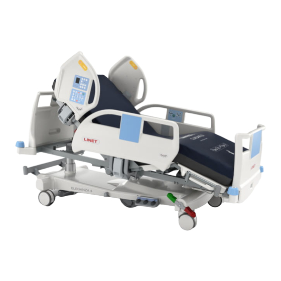
4 Product Description Fig. Bed Overview (Eleganza 4) Removable Head Board Head Siderail Mobi-Lift Handle - Bed Height Patient Control Panel Foot Siderail Removable Foot Board Corner Bumper Foot Board Lock Linen Holder Castor Control Lever Foot Switch - Bed Height Four-part Mattress support platform with Ergoframe®... -
Page 17: Technical Specification
5 Technical Specification All technical data are rated data and are subject to construction and manufacturing tolerances. 5.1 Identification of Applied Parts (Type B) All part of the bed (and accessories) the patient can reach are type B Applied Parts. ■ Mattress support platform Frame, Covers and all Movable Parts ■... -
Page 18: Environment Conditions
Version 2 2 x T3.15A L 250V for 120 V NOTE Upon request, LINET ® can deliver hospital beds with electrical specifications that comply with regional standards (custom voltage, different mains plugs). 5.6 Electromagnetic Compatibility Bed is intended for hospitals except for near active HF surgical equipment and the RF shielded room of a medical system for magnetic resonance imaging, where the intensity of EM disturbances is high. -
Page 19: Manufacturer Instructions - Electromagnetic Emissions
5.6.1 Manufacturer instructions - electromagnetic emissions Emission Test Compliance RF emissions Group 1 CISPR 11 RF emissions Class B CISPR 11 Harmonic emissions Class A IEC 61000-3-2 Voltage fluctuations / flicker emissions Complies IEC 61000-3-3 5.6.2 Manufacturer instructions - electromagnetic susceptibility Immunity Tests Compliance level Electrostatic discharge (ESD) -
Page 20: Use And Storage Conditions
Ground the mains. ► Use exclusively Hospital Grade or Hospital Only receptacles for grounding. Eleganza 4 is designed for use in rooms for medical purposes. Electrical installations must therefore meet local norms laying down the necessary conditions for electrical installations. ►... -
Page 21: Scope Of Delivery And Bed Variants
Brake Signal (o) ■ x-ray cassette holder (o) ■ EMR ready bed (o) ■ USB (o) NOTE It is not posssible to equip the Eleganza 4 bed with Attendant Control Panel and with Nurse Control Panel at the same time. D9U001GE4-0101_05... -
Page 22: Putting Into Service
Ensure that putting into service is performed exclusively by manufacturer´s customer service or trained hospital personnel. NOTE For safe, easy handling, LINET ® recommends having two technicians assemble the bed. Set up the bed as follows: ► Unpack the bed. -
Page 23: Head Board And Foot Board
8.3 Mattress support platform Eleganza 4 bed has 4-part Mattress support platform consisting of Backrest, Seat section, Thighrest and Calfrest. The Mattress support platform without x-ray cassette holder has 4 removable covers of Mattress support platform (1, 2, 3 and 4). -
Page 24: Potential Equalisation
8.4 Potential Equalisation The bed is equipped with a standard protective connector. This connector is used for potential equalisation between the bed and any intravascular or intracardiac device connected to the patient to protect the patient from static electric shocks. Use equalisation connector if: ■... -
Page 25: Before Use
8.5 Before Use Prepare the bed for use as follows: ► Connect the bed to the mains. ► Charge the accumulator. ► Raise and tilt the mattress support platform to the highest position. ► Lower and tilt the mattress support platform to the lowest position. ►... -
Page 26: Power Cable
9 Power Cable Attachment plug is means of connecting and disconnecting bed from the mains. Mains power cable must be attached with a hook at the head end of the bed during transport. CAUTION! Disconnecting bed from the mains does not stop motions of the bed! ►... -
Page 27: Replacing The Accumulator
Signalisation The LED (on Nurse Control Panel or Attendant Control Panel) indicates the accumulator charge status: Yellow LED Accumulator charge status Not lit Accumulator capacity is sufficient (charging completed) Short flashing (shortly lit, longer not lit) (circa 1.8 sec.) Accumulator is charging - continue charging until the LED is extinguished. -
Page 28: Removing The Bed From Use
Discharged accumulator This status will be cancelled automatically when the bed switches to sleep mode. The accumulator is regarded as discharged if the following condition is met: ► Defined decrease of voltage depending on discharging current ► This status is indicated by the accumulator status indicator flashing quickly. ►... -
Page 29: Manipulation
11 Manipulation WARNING! Risk of injury when adjusting the bed! ► Ensure that there are no body parts between the mattress support platform elements and the mattress support platform frame when adjusting the bed. ► Ensure that there are no body parts below the mattress support platform frame before adjusting the bed. 11.1 Siderails The split siderails are components of the bed in contact with patient. - Page 30 SIDERAIL DESCRIPTION (version with Nurse Control Panel) 1. Nurse Control Panel Fig. Siderails (version with Nurse Control Panel) 2. Siderail Handle 3. Correct Placement of Handset MANIPULATION 4. Siderail Release Handle 5. Angle Indicator To raise siderails up: ► Grab siderail by Siderail Handle (2). ►...
- Page 31 To release siderails down: ► Grab siderail by Siderail Handle (2). ► Unlock siderail by pulling Siderail Release Handle (4) to yourself. ► Fold down siderail slowly. SIDERAIL DESCRIPTION (version without control panels) Fig. Siderails (version without control panels) 1. Siderail Handle 2.
-
Page 32: Castor Control
11.2 Castor Control CAUTION! Material damage due to incorrect transport and involuntary movement! ► Prior to transport, ensure that the bed is disconnected from the mains. ► Ensure that the castors are braked prior to assembly, disassembly and maintenance. ► Ensure that the castors are braked when the bed is occupied. -
Page 33: Control Elements
11.4 Control Elements The bed is operated by different control elements. Control elements depending on the model: ■ Nurse Control Panel in both head siderails ■ iBoard Basic in both head siderails ■ Attendant Control Panel ■ Handset with illuminated buttons and with adapter for easy connection (Plug and Play) ■... -
Page 34: Nurse Control Panel (Optional)
11.4.1 Nurse Control Panel (optional) The Nurse Control Panel is the main Control Element for the caregivers. It is integrated in the outside of both head siderails. ► Ensure that exclusively trained nursing staff operates the Nurse Control Panel. Fig. Nurse Control Panel 1. - Page 35 NOTE: To activate CPR function (button ) the button is not needed. STOP BUTTON Pressing button immediately stops all electronic bed movements. LOCK To lock Backrest Adjustment: ► Press button LED Lock 6a, 6b and 6c are flashing. ► During flashing of the LEDs press any button 8. LED Lock 6a is lit.
- Page 36 To unlock Bed Height, Trendelenburg Tilt and Anti-Trendelenburg Tilt: ► Press button LED Lock 6a, 6b et 6c are flashing. ► During flashing of the LEDs press any button 12. LED Lock 6c is unlit. Bed Height, Trendelenburg Tilt and Anti-Trendelenburg Tilt are enabled again. LOCKED FUNCTION SIGNALISATION If LED 6a is lit, Backrest Adjustment is locked.
-
Page 37: Iboard Basic (Standard)
Scales Section (only version with scales) Eleganza 4 is optionally equipped with a weighing system that allows weighing the patient in bed. There are control buttons and display for the weighing system on the Scales section of iBoard Basic. Scales functions are described in chapter Scales Control. - Page 38 Statuses (iBoard Basic) Signalisation Meaning Required Action Function locked Unlock function GO Button not activated Activate GO Button Safe Working Load exceeded Remove load! OVERLOAD STOP System Fatal Error Contact service department SERVICE approved by manufacturer. Scales System disconnected and Bed Contact service department SCALE / BEA Exit monitoring disabled...
-
Page 39: Attendant Control Panel
11.4.3 Attendant Control Panel The Attendant Control Panel is a standard control element. The Attendant Control Panel can be hung on the foot board or on the siderails if required. The Attendant Control Panel can be stored in the Linen Shelf. It is possible to hold the Attendant Control Panel in the hand while operating. - Page 40 During this time the following is possible: ► Adjusting individual mattress support platform elements by pressing the corresponding function buttons. ► Disabling individual functions with the lock buttons. Each time a function button is pressed, the keypad will remain active for another 3 minutes. Function Buttons The function buttons 2, 4, 6, 8, 11, 12, 13, 14, 15 and 16 are described in chapter Bed Positioning.
-
Page 41: Handset (Optional)
11.4.4 Handset (optional) The handset is available with illuminated keyboard. NOTE The illumination is activated for 7s if any button was pressed and the illumination is activated for 3 minutes if GO Button was pressed. Thighrest Adjustment Button Thighrest/Backrest Lock LED Backrest Adjustment Button GO Button Autocontour Adjustment Button... -
Page 42: Foot Switch - Bed Height (Optional)
11.4.5 Foot Switch - Bed Height (optional) The foot control is optional and allows setting the Height of the bed or Examination Position with one’s feet. Protection Frame against Unwanted Activation Raise Mattress support platform Pedal Examination Position Pedal Lower Mattress support platform Pedal Fig. -
Page 43: Bed Positioning
11.5 Bed Positioning 11.5.1 Backrest To position Backrest use: ► Nurse Control Panel ► Attendant Control Panel ► Handset ► Patient Control Panel Fig. Backrest Angle on iBoard Basic Display iBoard Basic Display shows Backrest Angle. During continuous positioning Backrest stops automatically in 30 and 45 degrees. To continue in positioning release the button, then press and hold button until the desired position is reached. -
Page 44: Thighrest
1. Backrest Up Attendant Control Panel: 2. Backrest Down ► Press button ► Press selected part of Backrest Adjustment Button until intended position is reached. Fig. Backrest Adjustment Button (Attendant Control Panel) Handset: ► Press button ► Press selected part of Backrest Adjustment Button until intended position is reached. - Page 45 Nurse Control Panel: ► Press button ► Press selected part of Thighrest Adjustment Button until intended position is reached. Patient Control Panel: Fig. Thighrest Adjustment ► Press button Button (Nurse Control Panel, Patient Control Panel) ► Press selected part of Thighrest Adjustment Button until intended position is reached.
-
Page 46: Mechanical Calfrest Adjustment
11.5.3 Mechanical Calfrest Adjustment WARNING! Incorrect manipulation can injure the patient or the user! ► Hold the Calfrest by both Calfrest Handles at all times when lowering the Calfrest. ► Lower the Calfrest carefully to prevent it from falling suddenly. To raise the Calfrest: ►... -
Page 47: Bed Height
11.5.4 Bed Height To position Bed Height use: ► Nurse Control Panel ► Attendant Control Panel ► Handset ► Foot Switch - Bed Height ► Mobi-Lift Handle The bed stops above the lowest position during lowering, mattress support platform is adjusted to flat position and beep is performed. - Page 48 Attendant Control Panel: ► Press button ► Press selected part of Bed Height Adjustment Button until intended position is reached. Fig. Bed Height Adjustment Button (Attendant Control Panel) Handset: ► Press button ► Press selected part of Bed Height Adjustment Button until intended position is reached.
-
Page 49: Autocontour
11.5.5 Autocontour To position Autocontour use: ► Nurse Control Panel ► Attendant Control Panel ► Handset ► Patient Control Panel Nurse Control Panel: ► Press button ► Press selected part of Autocontour Adjustment Button until intended position is reached. Patient Control Panel: ►... -
Page 50: Examination Position
Attendant Control Panel: ► Press button ► Press selected part of Autocontour Adjustment Button until intended position is reached. Fig. Autocontour Adjustment Button (Attendant Control Panel) 1. Autocontour Up 2. Autocontour Down Handset: ► Press button ► Press selected part of Autocontour Adjustment Button until intended position is reached. - Page 51 Attendant Control Panel: ► Press button ► Press Examination Position Button until intended position is reached. Fig. Examination Position Button (Attendant Control Panel) Foot Switch - Bed Height: ► Press and release the middle pedal to activate the panel. ► Press and hold Examination Position Pedal until intended position is reached.
-
Page 52: Emergency Trendelenburg Position
11.5.7 Emergency Trendelenburg Position Fig. Emergency Trendelenburg Position/Trendelenburg Tilt To position Emergency Trendelenburg Position use: ► Nurse Control Panel ► Attendant Control Panel Trendelenburg position provides anti-shock conditions for the patient. During Trendelenburg Position Mattress support platform is straightened in the tilt. The LOCK function does not influence the Emergency Trendelenburg Position function! ... -
Page 53: Anti-Trendelenburg Tilt And Trendelenburg Tilt
11.5.8 Anti-Trendelenburg Tilt and Trendelenburg Tilt Fig. Anti-Trendelenburg Tilt To position Trendelenburg Tilt or Anti-Trendelenburg Tilt use: ► Nurse Control Panel ► Attendant Control Panel Depending on configuration, the bed stops in the horizontal position (0°) during tilting. To continue tilting press the corresponding tilt button. Nurse Control Panel: ►... - Page 54 Attendant Control Panel: ► Press button ► Press Trendelenburg Tilt Button until intended position is reached. Fig. Trendelenburg Tilt Button (Attendant Control Panel) Attendant Control Panel: ► Press button ► Press Anti-Trendelenburg Tilt Button until intended position is reached. Fig. Anti-Trendelenburg Tilt Button (Attendant Control Panel) D9U001GE4-0101_05...
-
Page 55: Cpr Position
11.5.9 CPR Position To position CPR Position use: ► Nurse Control Panel ► Attendant Control Panel In CPR Position the mattress support platform is adjusted to the lowest height and all the parts of the mattress support platform are in the basic (flat) position. Nurse Control Panel: ►... -
Page 56: Mechanical Bed Extension
11.5.10 Mechanical Bed Extension There are 2 positions of the Bed Extension. To extend the bed: ► Pull out the Safety Catches at Foot End on the both sides of the frame. ► Turn the Safety Catches by 90°. The Safety Catches are released. ►... - Page 57 Mattress Holder It is possible to adjust Mattress Holder when the bed without mattress is extended. To adjust the Mattress Holder: ► Remove the Calfrest cover from the mattress support platform. ► Insert the catches on both sides of the Mattress Holder to the selected positions. ►...
- Page 58 Fig. Basic position of the Mattress Holder Fig. First extension of the Mattress Holder Fig. Second extension of the Mattress Holder D9U001GE4-0101_05...
-
Page 59: Cardiac Chair Position
11.5.11 Cardiac Chair Position To position Cardiac Chair Position use: ► Nurse Control Panel ► Attendant Control Panel Nurse Control Panel: ► Press button ► Press Cardiac Chair Position Button until intended position is reached. Fig. Cardiac Chair Position Button (Nurse Control Panel) Attendant Control Panel: ►... -
Page 60: Mobilisation Position
11.5.12 Mobilisation Position To position Mobilisation Position use: ► Nurse Control Panel In Mobilisation Position bed is descending to the lowest Bed Height and Backrest reaches the maximum angle. Nurse Control Panel: ► Press button ► Press Mobilisation Position Button until intended position is reached. -
Page 61: Scales Control (Only Version With Scales)
12 Scales Control (only version with scales) Use iBoard Basic to control the scales. iBoard Basic 1. ZERO/T Button (tare or zero scales) 2. WEIGHT/CLEAR Button (cancel) 3. Scale interval switch button (0,5kg/0,1kg) 4. HOLD Button 5. Backrest Angle Indicator 6. -
Page 62: Hold Mode
12.4 Hold Mode Hold Mode can be used only when scales are stabilized. It allows adding or removing bed accessories and other items without changing the weight value. To activate Hold Mode: ► Wait until the scales are stabilized. The icon will be illuminated when the scales are stabilized. -
Page 63: Bed Exit Monitoring (Only Version With Scales)
13 Bed Exit Monitoring (only version with scales) Use iBoard Basic to control the Bed Exit Monitoring. If the bed is equipped with SafetyMonitor (accessory), Bed Exit Monitoring function is included between the functions of the Safety- Monitor. iBoard Basic 1. -
Page 64: Bed Exit Alarm
13.4 BED EXIT ALARM Alarm is triggered when patient has left selected monitored zone or PAUSE period elapsed and patient is not in ordered position. To stop Alarm: ► Press button Bed Exit Monitoring is deactivated and icon appears on the display. The audible alarm is stopped. -
Page 65: Equipment
14 Equipment 14.1 Accessory Rail with plastic hooks (optional) Accessory Rail with 2 plastic hooks is intended for hanging accessories. It is located on the sides of bed. Fig. Accessory Rail with plastic hooks (on side) 14.2 Linen Shelf (standard) Linen Shelf is intended for storing the things corresponding to its dimensions (e.g. -
Page 66: Mobi-Lift ® (Optional)
14.3 Mobi-Lift (optional) ® WARNING! Risk of injury due to slipping or falling when standing up! ► Ensure that the Mobi-Lift handles are completely inserted in the sleeve fittings. ► Ensure that no bed linen is caught between the sleeve fitting and the support handle. Mobi-Lift®... -
Page 67: X-Ray Examination (Optional)
14.7 X-Ray Examination (optional) WARNING! Respect maximum dimensions of x-ray cassettes! ► Maximum dimensions of any x-ray cassette for X-Ray Cassette Holder are 46,5 cm x 39 cm x 1,8 cm! WARNING! Prevent x-ray cassettes from being damaged! ► Do not leave any x-ray cassette in the X-Ray Cassette Holder if X-Ray Examination should not be performed! CAUTION! Prevent x-ray images from being devalued! ►... -
Page 68: Undercarriage Cover
14.8 Undercarriage Cover CAUTION! Risk of material damage due to objects on the undercarriage cover! ► Do not place objects on the undercarriage cover! Fig. 2-part undercarriage cover (standard) Fig. 1-part undercarriage cover (optional) D9U001GE4-0101_05... -
Page 69: Mattress
■ Virtuoso 15.1 Installation of Passive Mattress The passive mattresses intended for Eleganza 4 bed are equipped with straps with buckles (1) to fix mattress on the Mattress Support Platform. Fig. Bottom of Passive Mattress 15.1.1 Straps with side release buckles To fix mattress on the Mattress Support Platform:... -
Page 70: Installation Of Active Mattress
Fig. Fixation of the passive mattress with straps on the mattress support platform of Eleganza 4 bed 15.2 Installation of Active Mattress WARNING! Follow instructions for use of a compatible active mattress carefully! CAUTION! Risk of material damage due to an incorrect fixation of compatible active mattress on the mattress support platform! ► Adjust the bed to maximum Cardiac Chair Position before fixing all the straps of the inflated mattress to the... -
Page 71: Accessories
Fig. Fixation of active mattress with straps on the mattress support platform of Eleganza 4 bed 16 Accessories WARNING! Risk of injury due to incompatible accessories! ► Use exclusively original accessories from the manufacturer. The manufacturer is not responsible for the use of unapproved accessories. -
Page 72: Lifting Pole
► Attach a plastic grab handle with an adjustable strap to the lifting pole. NOTE The date of manufacture is marked on the grab handle. LINET® recommends replacing the plastic grab handle every four years. Fig. Lifting pole Fig. Places for lifting pole (sleeve fittings on accessory adapter) -
Page 73: Infusion Stand
16.2 Infusion Stand WARNING! Risk of injury due to use of incorrect accessories or because of incorrect use! Infusion Stands must only be used for their intended use. Always read the instructions for use! ► Only mount an infusion pump to the lower (wider) telescopic section of an infusion stand above the head/foot board. -
Page 74: Oxygen Bottle Holder
16.3 Oxygen Bottle Holder WARNING! Risk of injury with oxygen bottle holder due to incorrect use or due to careless driving! ► Ensure the oxygen bottle holder is correctly fitted in correct position. ► It is necessary to place oxygen bottle holder (with or without oxygen bottle) before transport to secure transport position. -
Page 75: Ventilation Circuit Holder
16.4 Ventilation Circuit Holder The ventilation circuit holder prevents extubation of the patient connected to the ventilator. ► Always use LINET ® ventilation circuit holder to prevent extubation during any procedures. Applying ventilation circuit holder: ► Put ventilation circuit holder in hole on right or left side of the Backrest frame. -
Page 76: Writing Shelf
16.5 Writing Shelf The Writing Shelf is intended for writing of nursing staff. It is placed in the handles of the foot board (as on the picture). Fig. Writing Shelf 16.6 Monitor Shelf The Monitor Shelf is suitable for transporting monitors with a weight of up to 15 kg. Installing the Monitor Shelf: ►... -
Page 77: Usb Connector (Optional)
16.7 USB Connector (optional) WARNING! Risk of injury due to incorrect use! ► Ensure accessory pluged in USB connector is in pristine condition! User of the bed is responsible for the fact that this requirement is met. CAUTION! Risk of material damage due to incorrect use! ►... -
Page 78: Safetymonitor
SafetyMonitor system consists of installed server, secure intranet infrastructure (Wi-Fi or LAN), screen in the nurse station (PC or tablet or smartphone), Tag on the wall, parked Eleganza 4 EMR ready bed with iBoard Basic, Integration Module, Localisation Receiver, LAN connector and LAN cable. - Page 79 1. siderail status (orange - siderail down) 2. backrest angle (orange - backrest in less than 30°) 3. bed height (orange - bed not in the lowest position) 4. brake status (orange - unbraked castors) Fig. Bed icon with bed statuses (orange - alerts/insecure statuses) D9U001GE4-0101_05...
-
Page 80: Cleaning/Disinfection
■ by competent authority of the country in which the mattress replacement system is to be used. 17.1 Cleaning (Eleganza 4) Prepare for cleaning as follows: ► Put the mattress support platform in the highest position. -
Page 81: Daily Cleaning
17.1.1 Daily Cleaning Clean the following bed parts: ■ All control elements for adjusting the bed ■ All handles □ CPR release handle ■ Bed ends ■ Siderails (in highest position) ■ Freely accessible mattress surface ■ Mobi-Lift® ■ Accessory rails 17.1.2 Cleaning before Changing Patients Clean the following bed parts: ■... -
Page 82: Troubleshooting
18 Troubleshooting DANGER! Risk of mortal injury due to electric shock! ► If a fault occurs, have the electric motor, power box or other electrical parts repaired by qualified personnel exclusively. ► Do not open the protective covers of the electric motor or the power box. Error/Fault Cause Solution... -
Page 83: Maintenance
Remove a defective bed from service and have the defective bed repaired. NOTE LINET ® recommends attaching the maintenance plaque to the bed. To keep the bed functioning correctly, ensure that the following maintenance work is performed at the correct intervals. -
Page 84: Electric Control
If the defect cannot be repaired, do not continue to use the bed. Technical Safety Check of the medical bed must be performed at least once every 12 months. The procedure for performing the safety check is stipulated in EN 62353:2014. NOTE LINET ® provides service documentation for qualified personnel. D9U001GE4-0101_05... -
Page 85: Maintenance Active Mattress
® Our responsible LINET ® Service partners will ensure your LINET ® products are up and running when you need them. For more information on available service support and contract offerings, please contact us at service@linetgroup.com and ask for tech- nical support. -
Page 86: Disposal
20.1 Environment Protection LINET ® is aware of the importance of environmental protection for future generations. Within the whole LINET company is applied the environmental management system, which is in accordance with the internationally agreed standards ISO 14001. The interna- tional system recognition and certifi cation ISO are based on the external audits executed by specialists from reputable international TŰV company. - Page 87 21 Warranty LINET ® will only be held responsible for the safety and reliability of products that are regularly serviced, maintained and used in accordance with the safety guidelines. Should a serious defect arise that cannot be repaired during maintenance: ►...
- Page 88 22.1 EU Declaration of Conformity (Eleganza 4 with scales) D9U001GE4-0101_05...
- Page 89 22.2 EU Declaration of Conformity (Eleganza 4 without scales) D9U001GE4-0101_05...
Need help?
Do you have a question about the ELEGANZA 4 and is the answer not in the manual?
Questions and answers