
Subscribe to Our Youtube Channel
Summary of Contents for Mitsubishi FREQROL-SF
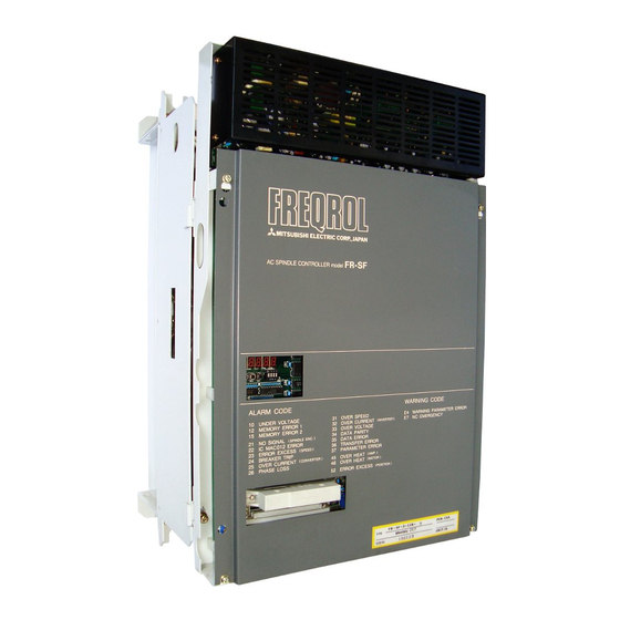
- Page 1 USA-E99991-075-* AC SPINDLE DRIV T R O U B L E S H O O T I N G A D V A N C E D AND EVER AOVAkCfNG MITSUBISHI ELECTRKZ...
-
Page 2: Table Of Contents
Troubleshooting ......... Status display and diagnosis . - Page 3 1.3.9 The orientation of the spindle is not correct ..1.3.10 The acceleration/deceleration time increases ..or zero speed signal is not issued ....1.3.12 The tapping operation cannot be correctly performed.
- Page 4 3.2.3 Where the equipment is linked with the NC using analog or digital signals ......3.3 Mounting position detector ......3.3.1 In the case of magnesensor type ....3.3.2 In the case of encoder type ......Adjustment ........... 3.4.1 In the case of magnesensor ......3.4.2 Encoder type ........
- Page 5 Appendix 2-2 Cable connection ......Cable connections (Bus linkage with NC) ..Appendix 2-3 Cable and Connector Specifications ..... Appendix 3 Main Circuit Configuration ..... Appendix 4 Spindle Part Layout ......Appendix 5 (Excluding printed circuit boards) Control Circuit Printed Circuit Board Part Appendix 6 Layout .........
-
Page 6: Troubleshooting
Otherwise, the equipment may be damaged. circuit board. rotating portion of the equipment. Next, thoroughly check the contents of Table 1.2, "Check They will help you contact Items upon Occurrence of Trouble". with Service Department of Mitsubishi Electric. - Page 7 Table 1.2 Check items upon occurrence of trouble Check what alarm the alarm display of theamplifier indi- cates. In addition, check old alarms in the alarm mode of the indication lamp (see Appendix 8). At which of phase R, S, and T a fuse is blown? (Control circuit input fuse) Does the trouble or fault repeatedly occur? Is the ambient temperature and temperature in the...
- Page 8 Table 1.3 Checking power voltage Checking Amplifier input pins See Appendix l-l AC power voltage Xl, X2, X3, and E Checking DC power Checking DC output supply voltage on See Appendixes 5, voltage at check printed circuit pins on SF-PW card board Table 1.4 Trouble...
- Page 9 1 Troubleshooting Situation ferenced The NC CRT (spindle monitor screen) indicates an alarm (as shown in the following figure). Spindle alarm 15 01 1.3.4 5 The motor does not rotate. The motor speed do not conform with that being 1.3.5 specified.
-
Page 10: Status Display And Diagnosis
1.1 Status display and diagnosis The status display and diagnosis are executed with the When linking display and switches on the SF-CA card. an NC and bus line, the status display and diagnosis can be executed on the NC CRT. 1.1.1 Status display and diagnosis from spindle amplifier For instructions for operating the display and switches,... - Page 11 1 Troubleshooting 1.1 Status display and diagnosis Shift DOWN EXTERNAL SIGNAL 3 sequence diagnosis. Item Display Description Represents the ready state. Represents the non-ready Check the contents of the external signal 1 (CTMl) and external signal 2 (CTM2) of input signals and external signal 3 (STSl) and external signal 4 (STS2) of output signals by comparing them with the following table.
- Page 12 (a) External signal 1 (CTMl) Check the contents of signals by each digit of LED using the following table. selectselect (b) External signal 2 (CTM2) Check the signal contents by each digit of LED using the following table. SVON Digit Servo Ready...
- Page 13 Troubleshooting 1.1 Status display and diagnosis Check the signal contents by each digit of LED using the following table. Servo Ready...
- Page 14 1 Troubleshooting 1.1 Status display and diagnosis Check the signal contents by each digit of LED using the following table. table. INSTANTANEOUS Warning which is issued when the POWER FAILURE power voltage temporarily drops. Warning which is issued when a SETTING ERROR parameter value exceeds the allow- able range...
-
Page 15: Status Display And Diagnosis From Nc
1 Troubleshooting 1.1 Status display and diagnosis (Note 1) Motion B - The motor decelerations and stops with regenerative braking and then base shut-off takes place. Whether to open the trouble signal contact FA-FC can be selected with a parameter. (See "CON Pin Nos. - Page 16 Display Description Represents the position loop gain state. It represents 0 when no position loop is formed. Position loop gain is obtained from the equation GAIN Motor speed (rad/s) Followed delay error (rad/) The standard value is 10. An error of real spindle rotation angle against referred spindle rotation angle is named droop.
- Page 17 Display Description Represents a control output being outputted from the spindle amplifier corresponding to bits. D / O...
-
Page 18: Checking Method And Countermeasures Of Trouble
Troubleshooting 1.2 Checking method and countermeasures of trouble classifi- cation A 1.2.1 When the amplifier is turned on at the first time, it Cause Check Remedy The amplifier is Visually check there is an abnor- knocked and damaged mal portion on the amplifier. when the equipment is operated or installed. - Page 19 Check Cause Remedy The parameters are them with the parameter list pro- meters. incorrectly set. vided by the machine manufacturer (Reference 1.2). The motor speed cannot D Check that the phase sequence of . o Correct the phase sequence. be increased (the alarm No.
-
Page 20: The Motor Which Has Normally Rotated Stops Abruptly
1 Troubleshooting 1.2.2 The motor which has normally rotated stops abruptly. Item Cause Check Remedy The fuse (Fl, F2, and/ or F3) is blown. a circuit tester (see and/or F3) with a new one. Alternatively, the NF Appendix 5). (See Section 2.1). After replacing the fuse with a new one or resetting the NF, if the same situa-... -
Page 21: The Equipment Does Not Work In Occasions
1 Troubleshooting Checking method and countermeasures trouble calssifica- tion 1 . 2 . 3 The equipment does not work in occassions. The orien- tation stop position deviates. Although an alarm appears, after turning on and off the power or resetting the equipment, the equipment normally works. -
Page 22: Checking Method And Remedy Of Trouble Classification
Checking method and remedy of trouble classification 1.3.1 When the power is turned on, the display of the opera- tion panel does not appear at all. Item Cause Remedy Check The AC power is not supplied. and X3 of the amplifier using a circuit tester. -
Page 23: When The Power Is Turned On, The Display On The
1.3.2 When the power is turned on, the display on the opera- the speed in the status tion panel does not indicate display mode (as shown in the following figure). Remedy Cause Check Item When the equipment is operation panel is as fol- linked with the NC lows, turn on the NC power through the bus, the... - Page 24 Troubleshooting 1.3 Checking method and remedy of trouble Check Remedy Item Cause The printed circuit board SF-CA card or is turned on, the dis- boards with the new ones. SF-TL card is defec- play on the operation panel tive. is as follows. The above Items 1 to 5 cannot be applied.
-
Page 25: An Alarm Appears Ont He Display On The Printed Circuit Board (Sf-Ca Card) Of The Amplifier
An alarm appears on the display on the printed circuit 1.3.3 board (SF-CA card) of the amplifier. As an example: Alternatively, an alarm appears on the NC CRT. As an example: Spindle alarm 15 32 The contents of the alarm which appears on the spindle amplifier are the same as those which appear on the NC CRT. - Page 26 Troubleshooting 1.3 Checking method and remedy of trouble classification Alarm Motion Name Abbr. Description (Note) The input power voltage drops to a value less than the specification assured value or an UNDER VOLTAGE instantaneous power failure occurs for 15 ms or more.
- Page 27 Name Description Abbr. (Note) u o . Parity error occurs in bus linkage with the M300 DATA PARITY series CNC. In bus linkage with the M300 series CNC, the shift command which exceeds the specific value DATA ERROR is issued from the CNC. In the bus linkage with the M300 series CNC, TRANSFER ERROR data is not correctly transferred.
- Page 28 [The voltage drop of the input voltage is detected. (Voltage between phase Item Cause Check Remedy The AC input votlage of the amplifier drops to input voltage drops and take a voltage which is less and X3 using a circuit proper countermeasures.
- Page 29 (3) Alarm No.15 (ME2) Memory Error 2 [The integrity of the contents of the 2-port RAM which communicates with the NC during initialization is checked.1 Cause Check Remedy Item The connector (CNlA) which is linked with the connector. tor and tighten the screws. NC through the bus is not securely connected.
- Page 30 (4) Alarm No.l7(BE) P.C.B error [Whether a component (especially A/D converter) on the printed cir- cuit board is normal or abnormal is checked. 1 Item Cause Check Remedy A component (especially, D Replace the SF-CA card with the new one and check that the new one.
- Page 31 1 Troubleshooting Checking method and remedy of trouble (6) Alarm NO.~~(NS~) N Signal 2 (Spindle ENC) phases [The signals of A, B, and C of the spindle orientation encoder are checked during orientation and synchronous tapping state.1 Remedy Item Cause Check The cable (MR-ZOLF) to the spindle orientation...
- Page 32 (Note) The correct output waveform of the encoder is as follows: while the bit 8 of the parameter ORSZ is 0: Phase A Phase B Phase 2 the bit 8 of the parameter OSR2 is 0, the same waveform as the above figure occurs.
- Page 33 (13) Alarm No.23(OSE) Speed Control Error Excess [The difference between the speed reference value and real speed is checked and if the deviation which is 50 rpm or more lasts for 12 sec. or more, an alarm occurs.1 Item Cause Check Remedy The phase sequence of...
- Page 34 1 Troubleshooting Checking method and remedy of trouble Item Cause Check Remedy the check pins on the printed circuit board SF-CA card using an oscilloscope. Phase A signal: CH44-CH9 (or AGA) Phase B signal: CH45-CH9 (or AGA) (See Appendixes 6(l) and (Note) Before using the check pins, the power of the amplifier should have been...
- Page 35 Check Remedy Item Cause The input power voltage at the input terminals Xl, X2, waveform is defective. and X3 of the amplifier using cable between the input an oscilloscope. power supply and amplifier. forms are as follows even in devices which generate the acceleration or decelera- distorted waveforms and tion state.
- Page 36 Troubleshooting 1.3 Checking method and remedy of trouble Cause Check Remedy The diode stack is same manner as the Item 5 defective. unit of the amplifier with above. a new one. 2.7. The surge absorbers and condensers are defec- as the Item 5 above. unit of the amplifier with tive.
- Page 37 1 Troubleshooting 1.3 Checking method and remedy of trouble (12) Alarm No.26(PL) Power Phase Lack [When R and T of phases R, S, and T are normal, whether there is phase S is checked.] Remedy Check Cause Item One of phases R, S, and lack and take proper T is lacked when the two phases of R, S, and T at...
- Page 38 Troubleshooting 1.3 Checking method and remedy of trouble (14) Alarm No.31(0S) Overspeed (The real speed of the motor is checked and when it exceeds 115% of the motor maximum speed, this alarm occurs.) Remedy Item Cause Check The reference speed speed.
- Page 39 (15) Alarm No.33(OV) [The voltage in the converter circuit is checked and if it exceeds 400 V, this alarm occurs.) Item Cause Check Remedy The input power voltage waveform is abnormal. alarm No.24, No.25, and No.32. No.32, check the waveform. cable between the input power supply and the ampli- fier.
- Page 40 External Clock Error [This alarm occurs when the system clock which is sent from the NC is defective.] [The parity of the data whick is trans- mitted from the NC is checked.] [This alarm occurs when the position refer- ence of the synchronous tap which is transmitted from the NC is too large.] [This alarm occurs when data from the NC is not completed.]...
- Page 41 Check Remedy Item Cause The bus interface cir- with a new one and check that card with a new one. the equipment correctly works card on the NC side is defective. A travel command which exceeds the specifica- reference exceeds tion value is issued from the program.
- Page 42 [This alarm occurs when the thermal protect which is installed in the controller exceeds the temperature being set.] (Ambient temperature: Fin temperature Remedy Item Cause Check The fan which cools the a new one. fin is defective. rotates. (See Section 2.3.) The ambient temperature of the amplifier is high.
- Page 43 Checking method and remedy of trouble (22) Alarm No_46(OHM) Motor Overheat alarm [This occurs when the thermal protec- tor which is installed in the motor exceeds the temperature being set (145"Cl.l Cause Check Remedy Item The motor cooling fan is defective.
- Page 44 (23) Alarm N0.52(0D) Over Droop [This alarm occurs when the position error becomes too large in synchronous tapping mode (for 8 rotations against the reference value.)] Cause Item Check Remedy The parameter #03 (PLG) which is set from the by referencing Reference value.
- Page 45 (25) Alarm No.57(OPE) Option Card Error Cause Check Remedy Item The option card does not conform with the conforms with the option card specification. name.
-
Page 46: The Motor Does Not Rotate
1 Troubleshooting 1.3.4 The motor does not rotate. Remedy Item Cause Check Trouble analysis issued, an alarm is indicated proper action by referencing on the display on the spindle Section 1.3.3. amplifier printed circuit board (SF-CA card). The control signal cable o Check that the cables are or power cable is in- correctly connected and correctly connected or... - Page 47 Remedy Check Cause The PIN1 and PIN2 of the printed circuit board (SF-PW module) is normal and PIN2 on the SF-CA card. the amplifier display (LED) SF-CA card are incor- does not indicate any mes- rectly set. sage. Check how the PIN1 and PIN2 are set.
-
Page 48: The Status Display Mode
1.3.5 The motor does not rotate at a speed being specified. Remedy Cause Check Item The phase sequence of the motor with that of the the wires U, V, and W speed reference and check amplifier. of the motor are not that the motor rotates only matched with that of at a low speed. -
Page 49: The Motor Vibrates And Is Getting Noisier During
1.3.6 The motor vibrates and is getting noisier during rotations. (Note) To distinguish between a fault of the mechanical portion including the motor and that of the amplifier including the speed reference, take the following procedure. rotate in the free run state. (ii) In the free run state, when the vibration and noise become smaller than the normal operation of the motor, it is supposed that the mechanical portion is normal. - Page 50 1 Troubleshooting 1.3 Checking method and remedy of trouble Remedy Check Item Cause common - ground (The control circuit common is the OM terminal of the terminal board TBl on the SF-CA card.) control circuit common (between each terminal of the main circuit and OM terminal) (Note) The insulation resist-...
-
Page 51: The Motor Overshoots In Speed Or Hours
1.3.7 The motor overshoots in speed or hunts. Cause Check Remedy Item The speed loop gain parameter is incorrectly values to the standard proportional gain (VKP) and set. values. speed loop differentiation gain (VKI) are set to 63 and 60 as their standard values, respectively. -
Page 52: The Cutting Force Degrades
1.3.8 The cutting force degrades Item Cause Check Remedy The ROM No. is in- correct. Appendix 11 Table 1.1. correct one. The torque limit com- mand is issued. input TLl and TL2 to turned on by referencing release the torque limit. Appendix l-4 or l-5. -
Page 53: The Orientation Of The Spindle Is Not Correct
1.3.9 The orientation of the spindle is not correct. (a) The orientation speed is not obtained. Check Remedy Cause The orientation command check that the control input sent from the operation is not issued. L bit 6 of ALM/DGN3 (see panel to the NC. - Page 54 Remedy Check Item Cause The detector (magne- rols by referencing the sensor or encoder) is ner that it does not per- description of the orienta- form the orientation and defective. tion control circuit check that the position feed- (Section 3). back signal is normal.
- Page 55 Remedy Item Cause Check Disconnect the connector CONE In the orientation replace the cable which is which is connected to the en- operation using an connected from the CONB to encoder, 5 V power is coder and check that 5V power the orientation encoder with is applied between the pin 4 not supplied to the...
- Page 56 Item Cause Check Remedy The orientation control Item 1 of (b), check that control circuit by referenc- circuit is abnormally the position feedback ing Section 3. set or defective. signal is normal. (Note) The following defective situations can be considered. a hunting.
- Page 57 C a u s e I t e m Remedy Check The parameter of the depends on the gear being ratio are as follows: gear ratio is incor- used. is weak..9" CRT screen parameter: #57(PR)to #64(PR .
-
Page 58: The Acceleration/Deceleration Time Increases
1.3.10 The acceleration/deceleration time increases. Remedy Cause Check Item The torque limit command D Check that the CON1 pin No.5 input TLl and TL2 to re- is issued. lease the torque limit. turned on by referencing Appendix l-4 or 1-5. The Ea ROM No. -
Page 59: The Speed Detection Signal, Up To Speed Signal, Or Zero Speed Signal Is Not Issued
The speed detection signal, up to speed signal, or zero speed signal is not issued. Remedy Check Item Cause The motor does not ro- signal 4 (STSZ) bit 2 (SD tion 1.3.4, take the re- tate. quired countermeasures. speed detection) or bit 5 turned on in the diagnosis mode on the status display. -
Page 60: The Tapping Operation Cannot Be Correctly Performed
The tapping operation cannot be correctly performed. 1.3.12 In case of synchronous tapping: Item Cause Check Remedy The parameter relating to the synchronous values. meters which are set on the tapping is incorrectly NC CRT display with the para- set. meter list on the machine and check them. - Page 61 Troubleshooting 1.3 Checking method and remedy of trouble Remedy cause Check The speed of the spindle 0 Change the parameter value in the open loop state motor deviates for 10 of the amplifier for the deviates: rpm or more. open loop state, input the speed reference and start replace the printed cir- command, rotate the motor...
-
Page 62: The Threading Operation Cannot Be Correctly
The threading operation cannot be correctly performed. Remedy Item Cause Check The orientation encoder of the spindle or the Item 3 of Section 1.3.12(a), printed circuit board with printed circuit board check that the waveforms at a new one. (See Section 2.4.2 or (SF-TL card or SF-OR the check terminals (CHl, 2.4.3.) -
Page 63: Checking And Replacing Parts
Checking and replacing parts 2. Checking and replacing parts When replacing (i) the entire amplifier or (ii) printed cir- cuit board SF-CA card (see Section 2.4.41, perform the items in the note. Remove the E2PROM (ROM31 on the SF-CA card (see Appendix 6(l)) from the old card and mount it on the new card in the following manner. -
Page 64: Replacing Fuses
How to insert E2PROM: of the pins of the E2PROM into the socket. are completely inserted into the socket holes, equally push the top side of the E2PROM. The sections that follow describe how to replace the fuses, thermal protectors, amplifier cooling fan, printed circuit boards, and motor cooling fan and how to check the transistor module and diode stack. - Page 65 Checking and replacing parts Replacing fuse Remove the leads for the cooling fan from the termi- nals RO and SO on the terminal block TBll. Loosen the mounting screws on the terminal block TBll and remove the terminal plate from the bottom plate. Loosen the mounting screws of the cement resistor RO (1 or 2 pieces) and remove the cement resistor(s).
-
Page 66: Replacing Printed Circuit Board
Checking and replacing parts Replacing printed circuit board (viii) When assembling the amplifier cooling fan, perform the reverse procedure as the disassembling procedure. (Note) After the cooling fan is replaced with the new one, check that the cooling fan name plate is observed from the outside of the amplifier. -
Page 67: Replacing Sf-Or Or Sf-10 Card
Remove the five nails on the SF-CA card (left figure) and loosen the two screws. Raise and remove the SF-CA card from the hinge panel. Last, insert your fingers into the cavities (2 posi- tions) on the hinge panel and remove the entire SF-CA card from the hinge panel. -
Page 68: Replacing Sf-Tl Card
(iii) After replacing the SF-OR (or SF-ORlO) card, assemble the parts being disassembled in the reverse procedure as the assembling procedure. (Note) When mounting the card, by pushing the connec- tor (rear side) from the front side with your fingers and check that the connector is securely connected to the card. -
Page 69: Replacing Sf-Ca Card
Replacing SF-CA card 2.4.4 Screw SF-PW (Power supply) - - C a v i t y Cavity+- SF-CA card Nail following option card from the SF-CA card. SF-OR card or SF-OR10 card or SF-TL card Remove the connectors (CONl, CON2, and CON3) on the SF- CA card and the connections on the terminal block TB2. -
Page 70: Checking Transistor Module
Adjustment Check Description Volume No. U phase current feedback zero adjustment less V phase current feedback zero adjustment (Note) When replacing the SF-CA card, first remove the new card. Checking transistor module (This method is the same both in the power side and regeneration side.) (a) 75 A or less (Note) The following figure shows the relationship between the terminal symbols and circuit diagram of the... - Page 71 and W which are connected to the motor. (ii) In the same manner as Section 2.4.4, to open CON101 to 103, remove the SF-CA card from the hinge panel. (iii) In accordance with the following criteria, check the electric continuity of each terminal and determine whether the transistor module is good or bad.
- Page 72 Criterion list (when x 10 R range of the circuit tester is used) Terminal to be Circuit tester No good checked terminal Shortcircuited, terminal Several 1Ofi Between indefinite Cl and C2El Shortcircuited, terminal Indefinite several 100 R Shortcircuited, terminal Indefinite Between several 100R Cl and Gl...
-
Page 73: Checking Diode Stack
Checking diode stack Copper bar (Note) The following figures show the relationship bet- ween the terminal symbols and circuit diagram of the above diode stack. connected to the termi- Remove the leads which are nals P and N. (ii) Check the electric continuity of each two terminals in accordance with the criterion list and check that the diode stack is good or no good. - Page 74 (Note) Even if part of the diode stack is defective, replace the entire amplifier with a new one. If it is necessary to replace the diode stack, by referencing Section 2.7, replace it with a new one. Criterion list (when x 10 R range of the circuit tester is used) Circuit tester No good checked...
-
Page 75: Replacing Transistor Module And Diode Stack
Replacing transistor module and diode stack (i) Disconnect the leads which are connected to the transistor module or stack and remove them from the heat radiation fin. (Note) Since part of the terminals G and E of the transistor module is of the insert type, when removing them, take care of it. -
Page 76: Replacing Motor Cooling
2.8 Replacing motor cooling (a) In the case of 132 frames or less (1) Remove the hex socket bolts which fasten the finger guard. Remove the P flat head screw which is located at the center of the cooling fan and only the fan can be dis- mounted. - Page 77 (4) Assemble the parts in the reverse order of the disassembling pro- cedures (1) to (3). Finger guard In the case of 160 frames or more: Remove the three hex. socket bolts which fasten the fan case and pull the fan case in the rear direction and the fan case with the cooling fan can...
- Page 78 Cut the three leads of the cooling fan which are connected in the terminal box. Remove the P flat head screw which fastens the cooling fan from the inside of the fan case and the cool fan can be dismounted from the fan case.
-
Page 79: Adjusting And Replacing Motor Built-In Encoder
Adjusting and replacing motor built-in encoder 2.9.1 Adjusting printed circuit board Motor built-in encoder Printed circuit board in motor terminal box Shaft A and B at the check pins on the above printed cir- cuit board using an oscilloscope. Phase A output ..Between PA and PGA Phase B output . - Page 80 (iii) Rotate the motor in the reverse direction (clockwise) and check that the following waveforms can be observed at the nearly same speed as (ii) above. Phase (iv) Press the pushbutton switch PBl (see Reference 1.1(2) and Appendix 6(l)) to reset the equipment to the closed loop.
- Page 81 Checking and replacing parts Adjusting and re- 2.9 placing motor built. in encoder (vi) Rotate the motor from a low speed to the maximum speed and check that it does not generate noise both in the forward rotation and reverse rotation. (Note 1) If the printed circuit board is defective: If the items for (ii) to (vi) cannot be adjusted on the printed circuit board which is...
-
Page 82: Replacing Encoder And Printed Circuit Board
Replacing encoder and printed circuit board (1) Remove the connector of the sensor from the printed circuit board in the terminal box. (2) Remove the three hex. socket bolts which fasten the fan case and pull the fan case in the rear direction. At the time, the fan case with the cooling fan can be dismounted. - Page 83 Checking and replacing parts Adjusting and re- 2.9 placing motor built- in encoder (5) Apply screw lock paint on the sensor mounting screws and plate mounting screws. (6) When assembling the fan case, fully extend the sensor leads into the terminal box to prevent them from getting caught.
-
Page 84: Spindle Orientation Control Circuit
3. Spindle orientation control circuit This chapter describes the maintenance, installation, and adjustment procedures for the electric orientation (fixed position stop) function which is provided to the spindle of an NC machine. -
Page 85: Structure
Spindle orientation control circuit Structure Structure 3.1.1 Spindle orientation using magnesensor (1 point) (a) Where speed selection signal function is provided: External signal Option card Spindle Controller Option card Orientation Speed selection signal Spindle CON2... - Page 86 Control Externa section signal last axis CNlA Option card S F - T L Magnesensor Spindle Controller Orientation command(bit) Option card Orientation position command (data) Bus line CON2...
-
Page 87: Spindle Orientation Using Encoder
3.1.2 Spindle orientation using encoder (4096 points, with index function) (a) Where the equipment is linked with te NC using analog or digital signals: command Controller Option card Orientation SF-?'I. command Orientation (12 bit binary) Spindle (Note) When the direction of the motor rotation differs from that of the encoder rotation, it is necessary to change the bit 8 and bit E of the parameter 0RS2 (amplifier parameter #30). - Page 88 NC through the bus: External signal To last axis Option card servo ampli- fier Terminatio resistor Controller N / C Option card Orientation position command (data) CN I A Bus line C O N A A Spi ndle C O N B C O N 2 (Note) When the direction of the motor rotation differs from that of the encoder rotation, it is necessary to change...
-
Page 89: Control Circuit And Parameter Setting
3.2 Control circuit and parameter setting 3.2.1 Where the speed selection signal function is provided (SF-OR card): (1) Setting parameters Although the contents of the parameters which are set by the amplifier are listed in Reference l-2.2(2), only the parameters relating to the orientation function are listed in the following. - Page 90 Spindle orientation control circuit Parameter D e s c r i p t i o n Setting range (unit) type (such gain) during stop set. Standard setting:4400 small like spindle GDz is dedicated machine, it should be set to Oriented Oriented spindle spindle...
- Page 91 Parameter Description Setting range (unit) The spindle orientation direction, detec- tor installed direction, and motor rota- tion direction are set. [Magnesensor orientation] Standard setting: 0020 (0120 when the detector installation direction is reversed) [Encoder orientation] Standard setting: 0120 (0020 when the detector installation direction is reversed) pindle stop Hexadecimal notation...
- Page 92 Setting range (unit) Description Parameter code out- Speed refer- , put in case of external Hexadecimal 0: Open emitter lent notation 0: Presence 1: Absence Position command, oriented spindle mode stop 0: Invalid 0: open emitter 1: Valid 1: open collec- signal in NC mode 0: Invalid...
- Page 93 Spindle orientation control circuit See Appendix g(2).
-
Page 94: Where The Equipment Is Linkedwith The Nc Through
Spindle orientation control circuit parameter setting 3.2.2 Where the equipment is linked with the NC through the bus (SF-TL card): Setting pins Although all setting pins are described in Reference tation are listed in the following. N o . Description Setting Name Outputs an encoder... - Page 95 (2) Setting parameters There are two types of parameters: one of which is set from the amplifier and the other is set from the NC CRT (being asterisked). The contents of the parameters are the same as those in Section 3.2.1(l). For instructions for setting parameters, see Reference 1.2.3.
- Page 96 Description Setting range (unit) Parameter 0: l/l Encoder gear Sets the gear ratio between spindle and 1: l/2 11 sgear ratio encoder. 2: l/4 3: l/8 Parameter Description Setting range (unit) Encoder Magnesensor Encoder spindle orientation: The spindle rotational angle at which Spindle creep speed starts is set.
- Page 97 No. of parameter error -Parameter Parameter Description Setting range (unit) Encoder Magnesensor [Encoder orientation] Oriented spindle stop position is set. The stop position is set within 360 deg. with increment of 360/4096. Data change during orientation stop state is valid from the next orienta- tion.
- Page 98 Spindle orientation Parameter Setting range (unit) Description Control type (such orien- as gain) during tation stop is set. setting:4400 Standard (When spindle GD2 is small like a dedicated machine, should be set to 6601.) Oriented Oriented spindle spindle tion stop KI magnific- ation Hexadecimal...
- Page 99 Spindle orientation Setting range (unit) Description Parameter The spindle orientation direction, detec- tor installed direction, and motor rota- tion direction are set. [Magnesensor orientation] 0020 Standard setting: (0120 when the detector installation direction is reversed) [Encoder orientation] Standard setting: 0120 (0020 when the detector installation direction is reversed) Oriented...
- Page 100 See Appendix 8(2). See Appendix g(3).
- Page 112 In addition, use the parameters being adjusted and check that each gear and each speed can be used. (Note) Adjust the stop position (point d) using the para- meter (PST). (Note) If the spindle hunts when the motor is stopped by the orientation operation, the selection of the mounting direction of the orientation detector is inverted.
- Page 113 Spindle orientation control circuit Set as follows: OSP=50, NG (The motor over- The spindle does not , runs when it stops.) vibrate when it stops. Increase PG2 (max. 40) Increase bits 8 to B (Kp magnification) and bit C Decrease CSP (min. 10) the parameter ORSl in the same ratio.
-
Page 114: Adjustment
Spindle orientation control circuit Adjustment The effects of four major parameters relating to the stability of the orientation are listed in the following table. Adjustment procedure Phenomenon The spindle overruns when it stops. (Note 1) Increase the parameter value. Decrease the parameter value. (Note 2) When the spindle remarkably hunts in the orien- tation stop state, since the selection of the... -
Page 115: Encoder Type
3.4.2 Encoder type Normal speed Speed value 220 Orientation, speed CSP: Standard value 20 (Creep speed) PG2: Standard value 20 2nd deceleration) point range value 180 point range Adjust the orientation parameters (OSP, CSP, PGl, PG2, and PST) in the following manner so that the best values can be obtained. - Page 116 Set as follows: OSP=SO, NG (The motor over- runs when it stops.) The spiondle does not vibrate when it stops. Increase PG2 (max. 40) Increase bits 8 to B (Kp magnification) and bit C Decrease CSP (min. 10) the parameter ORSl in the same ratio.
- Page 117 Spindle orientation control circuit Adjustment The effects of four major parameters relating to the stability of the orientation are listed in the following table. Adjustment procedure Phenomenon The spindle overruns when it stops. The orientation time is long. The spindle hunts when it stops.
-
Page 118: In The Case Of Magnesensor
3.5 Operation mode and motions In the case of magnesensor Sensor MS signal Sensor LS signal Orientation command Up to speed Slow down Orientation/ In the case where the rotation direction is reverse from the oriented rotation direction while the orien- tation direction is fixed to a specific direction (which is selected by a parameter). - Page 119 Operation (a) When the orientation command is turned on, the motor speed is switched from the operation speed to the ori- entation speed. up to speed signal is turned on. sor LS signal goes low, the slow down timer starts. (Software timer) orientation speed to the creep speed.
-
Page 120: Encoder Type
3.5.2 Encoder type (1) Operation mode Motor speed t----\ Orientation command Mark pulse Orientation complete Operation When the orientation command is turned on, the orien- tation position being specified by the parameter PST is read and the motor speed is changed from the opera- tion speed to the orientation speed. - Page 121 restores the speed at the speed reference which has been specified. (h) When the orientation operation is performed in the ori- entation state, the spindle rotates for one turn and then performs the orientation operation. However, depending on the orientation position and posi- tion shift (parameter PST) being set from the outside, the spindle rotates for 1 or more turns.
-
Page 122: Adjusting Synchronous Tap
4. Adjusting synchronous tap Setting parameters The following table lists the parameters relating to synchronous tap. They should be set by referencing the settting method. Setting value Setting method Parameter Set the time constant of the position command for synchronous tap. Fundamental specification rotated up to the maximum speed by the S... -
Page 123: Checking Operation
4.2 Checking operation 1) Check the operation of the spindle at a low speed. Example: G84 ZlO, Fl, 0 S50 Check that it 2) The spindle speed should be 50 rpm. rotates for 10 turns until it comes to the hole bottom and returns to the start position. - Page 124 Phenomenon Remedy 5) The lower hole is shallow and cutting chip is not correctly removed. correctly removed is used. The load is heavy and 1) Set the spindle parameter 0RS2 the spindle stops dur- bit B to 1 to select strong ing tapping operation.
-
Page 125: Appendix 1 Machine Connection
Appendix 1 Machine Connection Machine Connection Appendix 1 Power connection Appendix l-1 Amplifier Power supply ation. cribed in Appendix When the length of the power cable is long, its size should be large to prevent power fluctuation. - Page 126 Connection with motor (for standard motor) Appendix 1-2 Temperature signal is turned on. Appendix 3 [(l) Main circuit cables]. The cable for the motor detector should be a twisted pair shield cable whose length is 20 m or less. controller ground.
-
Page 127: Appendix L-2 Connection With Motor (For Standard Motor)
Machine connection Appendix 1-3 (without orientation (Standard)) Spindle amplifier Motor blower Motor detector Serial interface; Built-in encoder (Not used) (standard) Analog speed Motor temperature reference volt- switch age input Speed override Spindle fault command voltage output signal input (alarm signal) Zero speed output signal... - Page 150 Note) The setting pin names of the bare board drawing number G51 differ from those of G52. Number in parentheses are pin number of G52. Example:...
-
Page 151: Layout
1) Bare board drawing G51 part layout 2) Bare board drawing G52 part layout I 2 :i PIN4 (‘113 CN I B 1 2 3 C N I A C O N B C O N A A... - Page 152 (4) SF-PW module This module supplies all DC current to the entire FR-SF. AC170 to 253V input AC200 AC0 (Note) 1. The blocks B, C, D, E, F, G, H, and I are power supplies for the base amplifier of the main cir- cuit power transistors_ Note that they are not insulated from the main circuit.
-
Page 153: Major Part Table
Appendix 7 Major Part Table Appendix 7 Major Part Table Spare part class A __... The part should be replaced every 2 years. (Note) Spare part class B ..The part should be replaced every 5 years. Spare part class C . - Page 154 Appendix 7 Major Part Table Model name Part name Maker Code Remarks Nippon Chemicon Electrolytic 18.5 Nippon condenser condenser Cl-l- 5 Mitsu- magnetic bishi contactor FAN2 Tobishi Cooling fan Kosan 18.5 Chuo Denki Sizuki...
- Page 155 Appendix Major Part Table class Code Remarks Model name Maker Part name SHIZUKI SHIZUKI 18.5 Micron iesistor Denki RO-1 Micron RO-2 Denki OMRON OMRON Relay Thermal Tohoku OHD-60B Metal protector...
- Page 156 class Remarks Part name Model name Maker Code Tokoku Metal Current detector KOSHIN TE-K14-3 Terminal Mitsu- board bishi Terminal Mitsu- TE-K2-3 bishi board Noise filter SHIZUKI Toyo Fuse Fuse Matsuo Surge killer -5041 Electric Yamabishi BKO-NC6233 SF-PW Electric Module SF-CA Mitsu- SF-CA bishi...
- Page 157 Appendix 7 Major Part Table class Maker Code name name Mitsu- S F - O R S F - O R bishi Mitsu- (for option) S F - T L bishi Sony Magne- scale Magnet Yagnesensor Sony Magne- (option) scale Sensor Sony Magne-...
- Page 158 Appendix 7 Major Part Table Spare class Item name Part Model name Maker Code Q'ty ard Selection Remarks Capacity sory All2 B112 Bearing B132 (non-load) Cl32 A160...
-
Page 159: Appendix 8 Display Lamps (Led Diodes)
Appendix 8 Display Lamps (LED diodes) Appendix 8 Number Description LED1 Lights when the converter regenerates. Lights when the base of the inverter/converter tran- LED2 sistor cuts off. Watchdog alarm. Lights when the power is turned on or the machine is reset. In the bus linkage state, LED3 lights until the NC startup initializing operation is... -
Page 160: Appendix 9 Check Terminals
Appendix 9 Check Terminals (1) SF-CA card N o . Signal, description, waveform Common CH 1 DGA OV, DGA CH 2 OV, DGA CH 3 CH 4 CH 5 AGA CH 6 AGA Phase U voltage command Phase V voltage command CH 7 AGA Phase W voltage command CH 8 AGA... - Page 161 N o . Common Signal, description, waveform Phase V PWM modulation waveform Phase W PWM modulation waveform CH12 Phase U PWM modulation waveform CH13 Orientation stop Example of waveform) t t 300 psec Phase V reference sine wave CH14 Phase W reference sine wave CH15 Phase U reference sine wave CH23...
- Page 162 N o . Common Signal, description, waveform CH16 Phase W inverter current detector Phase U inverter current detector CH40 CH41 Phase V inverter current detector Example of wavefor) Motor acceleration N: Motor speed 11 K 15 K CH17 Phase U base amplifier driving signal Phase V base amplifier driving signal CH18 Phase W base amplifier driving signal...
- Page 163 Signal, description, waveform Common CH27 Phase R base amplifier driving signal CH28 Phase S base amplifier driving signal Phase T base amplifier driving signal CH29 Phase K base amplifier driving signal CH30 Phase F base amplifier driving signal CH31 Phase T base amplifier driving signal CH32 Example of waveform) Orientation stop state...
- Page 164 Appendix 9 Check Terminals Signal, description, waveform N O . Common CH25 Current amplitude command 0 X 1ov CH26 -10 V reference voltage -9.7 'L -10.6V Regeneration current limit state CH33 Example of waveform) Motor deceleration state Current limit state CH34 Regeneration overcurrent...
- Page 165 Signal, description, waveform Common Power voltage peak current CH36 Example of waveform) Motor stop state(M05) CH37 AD converter input (speed feedback and voltage command detection) Example of waveform) READY ON, Motorstop state 1 1 \! CH38 9.7 - 10.5 v Regeneration converter current detection CH39 Motor...
- Page 166 Appendix 9 Check Terminals N o . Signal, description, waveform Common Converter current detection CH42 CH43 Regular motor rotation Example of waveform) state Continued on the next page.
- Page 167 N o . Signal, description, waveform CH44 Speed feedback phase B CH45 Speed feedback phase A Example of waveform) Motor acceleration state Motor speed (rpm) CH46 Analog speed reference voltage Example of waveform) Regular motor rotation state CH47 Inverter base amplifier output Phase U CH48 Inverter base amplifier output...
- Page 168 Signal, description, waveform Common Example of waveform) Orientation stop state...
- Page 169 (2) SF-OR card Common Signal, description, waveform CH 1 Position feedback phase A Encoder orientation CH 2 Position feedback phase B state (1024 P/r) Position feedback phase Z Example of waveform) State of clockwise rotation viewed from a, b, c, d =I,< Position feedback encoder speed (rpm) Magnesensor output...
- Page 170 Appendix 9 Check Terminals Signal, description, waveform Common State which the magnesensor Example of waveform) mounting disk rotates at 10 . ~ (se,’ 1 N: Speed of magnesensor mounting disk (rpm) CH 6 0 V, DGA For AGA (analog common), use the SF-CA card terminal board OM.
- Page 171 (3) SF-TL card Signal, description, waveform CH 1 Position feedback phase A\ Encoder orientation Position feedback phase B CH 2 state (1024 P/r) CH 3 Position feedback phase Z Example of waveform) State of clockwise rotation viewed from encoder axis N: Position feedback encoder speed (rpm) CH 4 Magnesensor output...
- Page 172 Appendix 9 Check Terminals Signal, description, waveform Common Example of waveform) State which the magnesensor mounting disk rotates at 10 2 .I 0 N: Speed of magnesensor mounting disk (rpm) For commons DGA and AGA, use the SF-CA card.
- Page 173 SF-PW module DC output voltage Check terminal Block Between P5A and Between P24A and DO24 Common Between AGA and between tion Between ACDOWN put voltage is not and DO24 supplied or it is 160 V or less) Between P15F and DlOF -10% and between NlOF and -lov...
-
Page 174: Appendix 10 Parameter Setting List And Short Pin Switch
Appendix 10 Parameter Setting List and Short Pin Switch (1) Example of parameter setting list... - Page 175 The value can be set from the NC. initially set. Order list B N 4 0...
- Page 176 2. Setting description of short pins switch in cards settings means that the For pin in the table, pin is to be inserted; g mean hat the pin is N o t c h to be removed. 2. SW5 should be set in the o mark side. numbers 3.
- Page 177 Table 1.1 Major structural components (l/3) Number of ROM3 IEaPROM) designates the model of corresponding motor which is identical with the description on a sub-plate (model of corresponding motor) stuck next to the name plate for rating of amplifier. of spec- No.
- Page 178 Table 1.1 Major structural components (Z/3) of spec- No. of Applicable AC spindle motor Printed circuit ification amplifier ROM drawing No. Applicable ampli- board drawing drawing fier or name Model (List of) Detailed Option ROM2 ROM3 order (list SF-OR10 SF-OR FR-SF-2 550wooo 550wooo...
- Page 179 Table 1.1 Major structural components (3/3) Printed cir- Printed cir- specification cuit board Remarks Name drawing name drawing Magnetizer Magnetic Magnetic sensor for sensor orientation Amplifier With speed select signal SF-OR10 function Speed select signal function plus magnetic SF-OR sensor orientation Connection with NC by bas connection plus magnetic SF-TL...
-
Page 180: Appendix 12
Appendix I2 Maintenance Instru- ment Maintenance Instruments Appendix 12 (1) Instruments for adjustment Instruments in Table 1.2(a) are for adjustment and those in Table 1.2(b) are for repair of troubles. Instruments for adjustment Table 1.1(a) Specifications Application Name Check of AC power Within 1V - 300V AC volt meter supply voltage... -
Page 181: Reference: Setting And Adjustment
pins, and volumes Setting and Adjustment Reference. Set switches, setting pins, and volumes For the parts positions of the main panel and hinge panel of the amplifier, see the component layout (Appendix 5). For the parts positions on the control circuit printed circuit board, see the component layout (Appendix 6). - Page 182 (2) Pushbutton switches Name Description Switches the LED display mode. Whenever this switch is pressed, the mode is rolled over in the order of status display MODE meter (8) + debug. Changes the current page to the next page in the same mode.
- Page 183 (4) Setting pins Name Setting Description Bus interface When the equipment is not linked to setting the M300 series machine through the bus. * The parameter PIN1 should be set PIN2 at the same When the equipment is linked to the time.
-
Page 184: Sf-Gr Card
pins, and volumes SF-OR card 1.1.2 (1) Setting pions (Note) The set pin No. after the bare board drawing N o . Description Remarks Setting Name The baud rate of the Not used CON60 serial inter- face becomes 9600. Baud rate selection The baud rate of the Not-used... -
Page 185: Sf-Tl Card
SF-TL card (1) Rotary switch Name Description Axis number setting rotary switch. (2) Volume (Note) After the bare board drawing number G52, VRl is not provided. Name Description Sensitivity of magnesensor (3) Setting pins Setting Description Name Outputs an encoder feedback signal from CONB to CONAA. - Page 186 Name Setting Description Not supplied from NC Orientation encoder power Supplied from NC SF-OR card ..with encoder orientation 1.1.4 (Note) After the bare board drawing BN624A905G52 card, the pin No. becomes "PIN". Remarks Name Setting Description Not supplied from NC Orientation...
-
Page 187: Setting Parameters
Setting parameters When driving a machine using the spindle motor, it is necessary to determine parameters so that the perform- ance of the machine can be maximized in accordance with the machine specifications and motor characteristics. Because the contents of the parameters just depend on the machine to be used, refer to the parameter list provided by the machine manufacturer. -
Page 188: Display And Set Switches (On Sf-Ca Card)
1.2.1 Display and set switches (on SF-CA card) Changes the dis- play mode. Increments a value on the display area. Decrements a DOWN: On SF-CA card on the display area. Stores set data of the parameter. a) The display modes are roughly categorized as 12 modes consisting of status display, diagnosis, alarm, parameters b) After the equipment power is turned on, unless there is an alarm cause, the display area on the set panel displays... - Page 189 LED DISPLAY FUNCTION FR-SF diagnosis, alarm, parameter (1) to (8), etc., press the MODE switch. To change the current display in the same mode, press the UP and (or) DOWN switches. The parameters are categorized as groups (1) to (8). To display the next group, press the MODE switch.
-
Page 190: Setting Parameters From Spindle Amplifier
Setting parameters from spindle amplifier 1.2.2 Setting parameters To set parameters, the machine ready complete READY signals SET1 and SET2 (see the description of "Connect- ing machines" in Appendixes l-4 and l-5) have been set to OFF. the display area of the setting panel indicates the speed in the status display mode (Figure 1). - Page 191 Reference Setting and In addition, the data corresponding to the address appears. (Example) state as shown in Figure 2, Gi When the switch is pres- appears. sed once again, [:t: appears. (Figure 3). When pressing the @ switch in the state as shown in Figure 3, When pressing the same switch once again, C: appears.
- Page 192 Press them switch to reset the Alternatively, turn off FR-SF. the power and then turn on it. Now that the data set operation has been completed.
- Page 193 Setting range Description Parameter (Unit) The setting depends on the motor specifica- tion. 0: Standard specification 2: Special specification Decimal Motor type When selecting "O", #02 MSL parameter is set and the applicable motor is selected. When selecting "2", the parameters of #81 to YAF are set.
- Page 194 Reference Setting and Adjustment Setting parameter Setting range Description Parameter (Unit) The setting depends on the number of pulses of the encoder. 0: 1024 pulses Position loop Decimal (Encoder orientation tapperless) encoder type 1: 90000 pulses (for controlling the axis C) (not used) This parameter is set by interface with the external machine (NC).
- Page 195 Reference Setting and Adjustment Setting parameter Description Parameter (Unit) The offset value where the analog speed refer- Signed deci- Speed reference ence signal is used is set. Generally, it is mal notation adjusted using the offset variable resistor offset on the NC. -999 - +999) Standard setting: 0 Not used.
- Page 196 Parameter No. on the NC screen when the equipment is linked with Parameter No. on the NC screen when the equipment is linked with Parameter Description Setting range (Unit) Encoder Encoder orientation: The angle of the creep speed is set. Standard setting: 180 Orientation 21 33...
- Page 197 Parameter No. on the NC screen when the equipment is linked with Parameter No. on the NC screen when the equipment is linked with...
- Page 198 Parameter No. on the NC screen when the equipment is linked with Parameter No. on the NC screen when the equipment is linked with Description Setting range Parameter (unit) Control type (such as gain) during orien- tation stop is set. Standard setting:4400 dedicated machine, 6601.1...
- Page 199 Parameter No. on the NC screen when the equipment is linked with screen Parameter No. on the NC when the equipment is linked with bus: Parameter Description Setting range (unit) The spindle orientation direction, detec- tor installed direction, and motor rota- tion direction are set.
- Page 200 (Note) Set the ORS2 orientation detector's direction (bit 8) and position loop detector's direction (bit E) from the relationship between rotations of the motor and detector by referencing the following mounting schematic. Encoder (bit 8, bit E) 0: (+) direction 1: (-) direction Belt Motor...
- Page 201 Reference Setting and Adjustment Setting parameter -Parameter No. on the NC screen when the equipment is linked with through the bus: Parameter No. on the NC screen when the equipment is linked with through the bus: Parameter Description Setting range (Unit) 1 to 3276 (10 rpm).
- Page 202 Parameter No. on the NC screen when the equipment is linked with No. on the NC screen when the equipment is linked with Parameter Setting range (Unit) Description 1 to 7FFF (Hex). The number of gear teeth on the spindle However, on the NC side against the gear 00 is converted screen, it is in the...
- Page 203 Parameter No. on the NC screen when the equipment is linked with Parameter No. on the NC screen when the equipment is linked with bus: Parameter Description Setting range (unit) F E D C B A 9 8 7 6 5 4 3 2 1 0 Speed refer- Alarm code at- in case of...
- Page 204 Reference Setting Adjustment Setting parameter Setting range Description Parameter (Unit) Not used. 0 should be set. When "1" is set to Y45wT bit 8, this parameter is valid. In the synchronous tap state, Kp and ki magnifica- tions which are differ from those of the orienta- tion are set.
- Page 205 Reference Setting and Adjustment 1.2 Setting parameter Setting range Parameter Description (Unit) When the number of gear teeth exceeds the setting Number of range of the normal gear teeth parameters (GRAl to 4A GAH2 auxiliary gear 4 and GRBl to 41, assuming that the number of gear teeth on spin- teeth is X x Y, X and Y are set to the gear teeth dle side parameter and auxiliary teeth parameter, respec-...
- Page 206 A 82 A 83 A 84 A 85 A 86 A 87 A 88 A 89 DILT QILT Continued on the next page. parameters are those being set by Mitsubishi. For the setting values, see "Parameter list" provided with the controller.
- Page 207 A B5 CKWI A B6 CKWF A 07 CKWSO A 88 CKWS A BA CSFT Continued on the next page. A marked parameters are those being set by Mitsubishi. For the setting values, see "Parameter list" provided with the controller.
- Page 208 Setting range Parameter Description (Unit) 0 should be set. Not used. The magnification of 121 PGl (orientation 1st 1 to FF tion by gear Hexadecimal Gear 01 Gear 00 Gear 10 Gear 11 This parameter is set when the orientation When 0 is set, should be adjusted by each gear.
-
Page 209: Setting Parameters From Nc (On 9" Crt Screen)
1.2.3 Setting parameters from NC (On 9" CRT screen) By pressing the menu key meter screen appears. The spindle parameters are categorized as parameters which are controlled on the NC side and those which are controlled on the spindle side where the spindle controller FR-SF is linked with the NC through the bus line. - Page 210 While observing the contents of the data display area, enter data to be changed. (Example) To change the data 2 6 4 0 , in the order. Check the contents being dis- played in the setting area BASE SERVO and set the data by the fol- MENU lowing operation.
- Page 211 (2) Parameters being controlled on NC side By pressing the menu key ]emy, the spindle para- meter screen appears. 114" CRT screen1 [SPINDLE SPEC. 1 S P I N D L E 34 PG2 10.00 3 smaxl smini 10 sari 2640 0 soft Setting range...
- Page 212 Setting and Setting range Description Item (Unit) The spindle minimum speed Even if the S is set, command which is less than Min. 0 - 32767(rpm) mini this value is issued, the speed spindle rotates at this speed. Not used. 0 should be set.
- Page 213 (3) Parameters to be controlled on spindle amplifier side key, the spindle parameter screen By pressing the These parameters are sent from the NC when the spindle amplifier is linked with the bus line. (Note 1) Although the same parameters can be set from the spindle amplifier, when the bus line is linked, those being set from the NC become valid.
- Page 214 Description Setting range (Unit) Parameter # I No Encoder Magnesensor Encoder orientation: The angle of the creep speed is set. Standard setting: 180 Orientation 1 33 21 PGl 1st decelera- Magnesensor orientation: The time taken for start of creep tion point speed after passing over linear zone is set.
- Page 215 Parameter Description Setting range (unit) Control type (such as gain) during orien- tation stop is set. Standard setting:4400 (When spindle GD' is small like a dedicated machine, it should be set to pindle stop Hexadecimal notation combina- combina- tion tion tion [times] 0: 0.6...
- Page 216 Reference Setting and Adiustment Setting parameter cameter No. of eter error. Description Parameter Setting range (unit) spindle orientation direction, installed direction, motor direction set. gnesensor orientation] 0020 Standard setting: when detector installation irection reversed) coder orientation] 0120 Standard setting: when detector installation irection...
- Page 217 ter error Setting range (Unit) Description Parameter The motor maximum speed is set. Motor maximum (The speed when the analog reference 0 - 32767 (i-pm) speed speed is 10 V) The speed for the zero speed output is Motor zero set.
- Page 218 Reference Setting and Adjustment Setting parameter +-Parameter Setting range (Unit) Description Parameter For gear 00, the number of gear teeth on the spindle side is set. This signal is used for synchronous tap cycle and orientation operation. For gear 01, the number of gear teeth on the spindle side is set.
-
Page 219: Adjusting Speed And Load Meter
Adjusting speed and load meter The speed meter can be adjusted when a speed meter (DC ammeter full-scale: 1 mA) is connected between the ammeter terminals SMl and OM (see Appendixes 1-4 and l-5). Turn on the dip switch SW5-4 on the SF-CA card (see Reference 1.1.1 (3)) so that the speed meter reads the full Section 3.1.1 (3)) so that the speed meter reads the full scale (the maximum speed which is set by the parameter...
Need help?
Do you have a question about the FREQROL-SF and is the answer not in the manual?
Questions and answers